Week 7 State of charge estimation
Q.
1. Simulate the 3 test cases from harness dashboard and write a detailed report on the results
2. What is coulomb counting? Refer to the above model and explain how BMS implements coulomb counting for SOC estimation?
Hint :(Download the file from the link and go to SOC estimation model-ECU block)
Ans.
1.
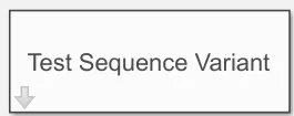
This simulation model has the BMS closed loop system with a harness board that enables selection of test case and indicates the present state of the BMS. Closed loop system implements BMS ECU and the plant model. Battery is 80% charged before the beginning of simulation. Different driving scenarios can be defined using the Test Sequence Variant subsystem shown below.
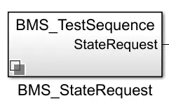
Test sequence that needs to be determined by the above block is given by the BMS_TestSequenceStateRequest subsystem shown below.
Test Case 1
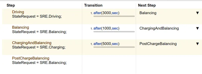
The first test sequence is as shown below. Considering the system is a part of EV powertrain, it begins with the driving state and continues till 3000s. Then it stops and rests for 1000 s. It is switched to charging mode for 5000 s, after which it again rests and the balancing mode kicks in.
Results
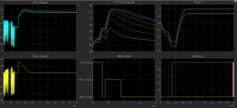
Here, the individual cell voltages change as he load current changes during the driving state. The model is initialized with SoC imbalance in individual cells; hence voltages are different. By the end of simulation, the voltages converge because of balancing procedure. During the CCCV charging state, current is a constant 30A and then starts reducing once voltage hits 4.2V. It reduces to zero until SoC reaches 1. The temperature graphs show significant discrepancy among the hottest and the coldest cell. This is because of the asymmetry in module layout in terms of thermal behavior. Cell 6 gets hotter than cell number 1 because it is thermally insulated on one side. SoC estimation based on three different methods (EKF, UKF and coulomb counting) are plotted. SoC estimators were initialized to 80% to access their capability to recover. Coulomb counting doesn’t recover this error. Both Kalman filter algorithms recover from this initial error within one hour of operation and EKF outperforms the UKF.
Test Case 2
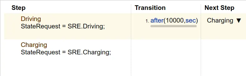
The test case to start with driving mode for 10000s and then charging for the rest of simulation.
Results
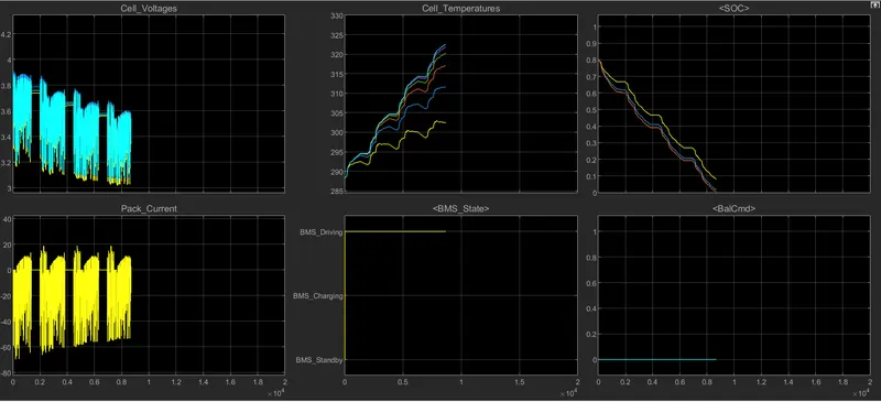
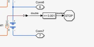
Here, the simulation doesn’t run till charging mode since and stops before that. This happens because deep discharge happens to the cells. Four drive cycles are repeated after which the cell capacity is exhausted, and they reach almost 0% SoC condition. As per the diagram below from the plant model, simulation stops when SoC goes less than or equals 0.001.
Balancing never happens since there is no standby mode in the test case. Cell voltages keep declining because of the decreasing SoC levels. Charging currents are also limited over the time due to temperature rise in cells.
Test Case 3
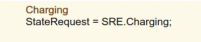
The test case has only one mode which is charging.
Results
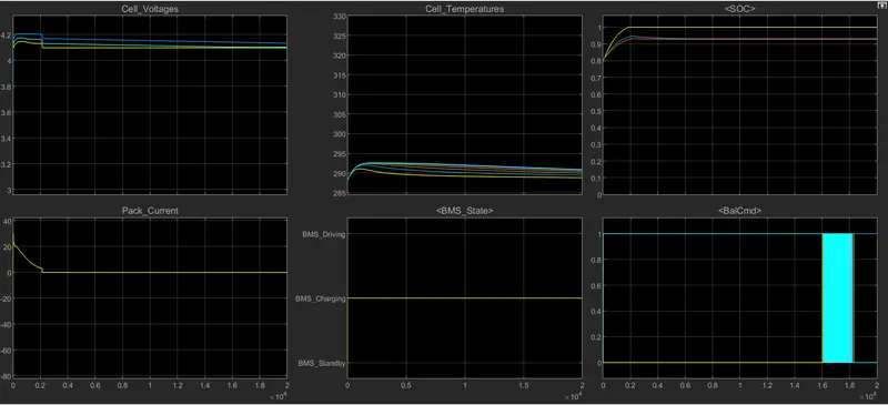
Since cells have an initial 75% SoC, the coulomb counting estimation of SoC reaches a 100% within 2000 s. CCCV charging is followed and current decreases once 4.2V is reached. Charging stops once SoC reaches 100%. The current then becomes zero, cell voltages come to equilibrium states. Balancing commands are enabled for all cells except cell 1 from the beginning. At 16000s cells 1 and 6 reach same voltage values. Cell 2 keeps reducing but takes longer since the voltage value is highest for it initially.
2.
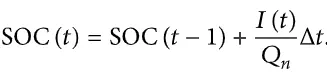
The Coulomb counting method measures the discharging current of a battery and integrates the discharging current over time in order to estimate SOC. Coulomb counting method is done to estimate the SoC(t), which is estimated from the discharging current I(t), and previously estimated SOC values, SoC(t-1). SOC is calculated by the following equation:
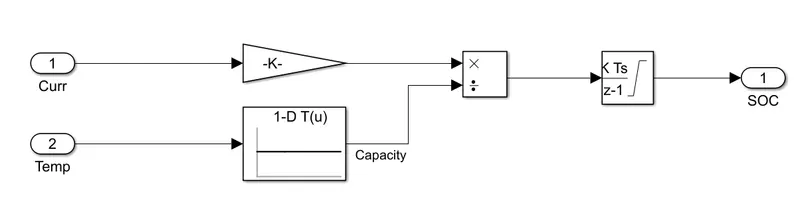
The figure above shows the implementation of Coulomb Counting in the simulation model.
The charging/discharging current is integrated over time using a discrete integrator block. The initial value of SoC in the block is kept as 5% extra to check if the method will recover from the error. This integrated current gives charge in the unit Ampere seconds. This is divided by a constant 3600 to get the coulomb transfer in Ampere hours. The ratio of this columbic charge over the actual capacity of the cell gives SoC. Here, the actual capacity of a cell is taken from a look-up-table that gives Ah capacity corresponding to the cell temperature.