Week 7 State of charge estimation
ANS 1:
simulation of the 3 test cases-
introduction:
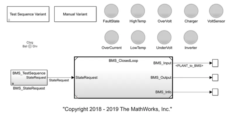
1 . the model has test sequence block, manual variant block, all the sensors are highlighted in circles.
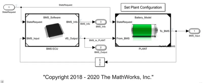
2. after receiving the state request, the BMS closed loop operates and calculates the input, output and Information regarding the BMS,
3. It integrates various components to provide a comprehensive view and control over battery simulation or testing processes, as a result facilitating both development and operational phases of battery-powered systems.
4. the above image is of the dashboard where various parameters and data related to the battery model and its operation are displayed and controlled.
5. It provides real-time 0data such as voltage, current, temperature, state of charge (SoC), state of health (SoH), and other relevant metrics.
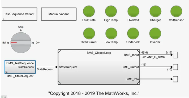
6. the green signals in the below image shoes that there are no errors in the Simulink model.
analysing test case 1:
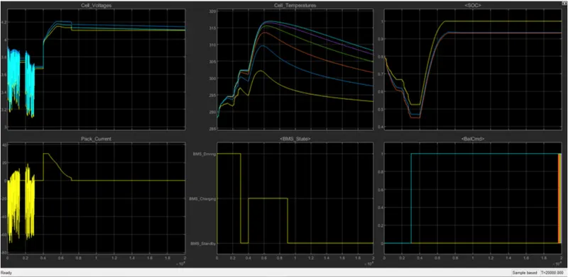
1. from the above image - initial state of the vehicle is driving state.
2. the maximum charging was done till 90%.
3. next mode after charging is standby mode.
4. cell voltage goes to top 4.2V and settles there for maximum time of operation.
5. BMS driving standby and charging graphs are also shown in toggle states.
6. cell voltage and pack current are heavily varying while driving.
7. the temperature is increasing in the above operation.
8. while charging, the temperature shoots up heavily. the voltage increases and goes to maximum in some time and the current variation is also shown.
9. while on standby, the voltage stabilizes, the current is not drawn so it is effectively zero, the temperature gradually decreases, the SOC is constant and no current is drawn for any operation.
.
test sequence 2:
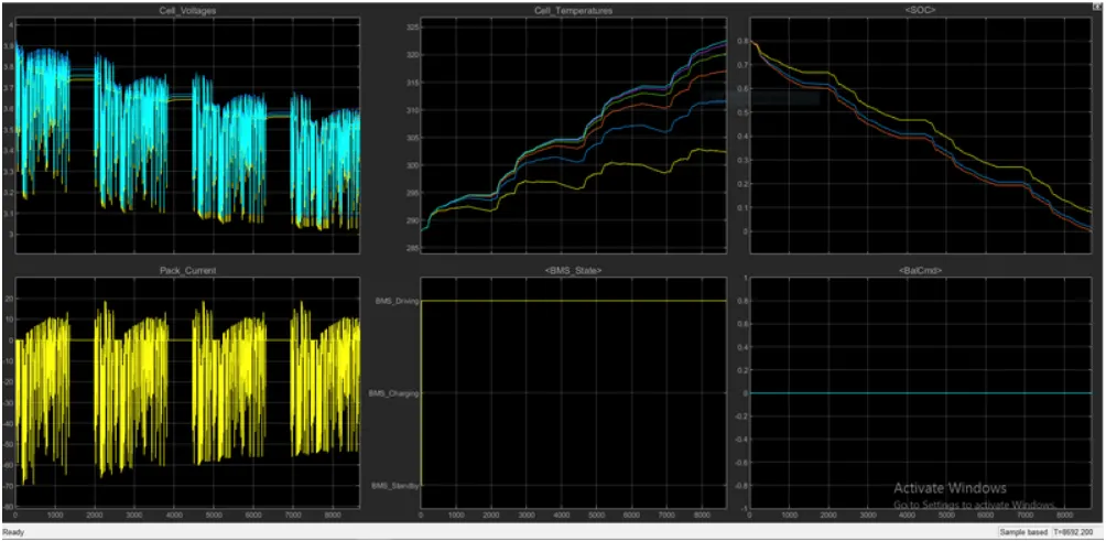
1. since the vehicle is in driving condition, the temperature increases gradually as a result of battery current satisfying the on road demand.
2. the SOC decreases as only driving condition is met. no charging or standby is shown in the simulation.
.
sequence 3:
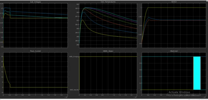
1. only charging takes place in this simulation.
2. voltage falls gradually following a linear graph for most of the time.
3. current reaches zero very quickly as the voltage drop is sudden less than halfway of the simulation.
4. SOC shoots up to maximum very quickly.
5. the temperature shoots while charging initially and then falls gradually.
.
ANS 2:
What is coulomb counting? Refer to the above model and explain how BMS implements coulomb counting for SOC estimation ?
Coulomb counting:
Coulomb counting is a method used to estimate the state of charge (SOC) of a battery by integrating the current flowing into or out of the battery over time. It relies on the principle that the amount of charge (in coulombs) entering or leaving the battery can be directly related to the SOC.
1. The Battery Management System (BMS) continuously measures the current flowing into or out of the battery. This can be done using a shunt resistor or a Hall-effect sensor placed in series with the battery.
2. The BMS integrates the current over time to calculate the total charge that has entered or exited the battery. This integration is typically done using a microcontroller or dedicated IC within the BMS.
3. SOC=(Charge Counted/Total Capacity)×100%
4. then the analog current signal is converted into a digital format suitable for processing by the BMS's microcontroller or processor.
5. The BMS continuously integrates the measured current over time to accumulate the total charge. temperature and operating conditions may affect this integration.
6. To accurately estimate SOC, the BMS requires knowledge of the battery's total capacity. periodic recalibration routines are of help here.
7. Using the integrated charge and the known battery capacity, the BMS calculates SOC as described.
BMS representation in image is below:
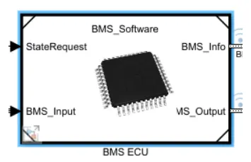
BMS ECU block is below:
inside ECU, SOC estimation block has coulomb counting box which has the following Simulink logic implemented:
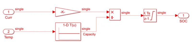
1. Inputs are temperature and current from battery.
2. These inputs are given for integration where current will be integrated with respect to time.
3. This output is given to another block where it is divided by battery capacity.
Hence SOC is calculated by this method.