Week 7 State of charge estimation
1.Simulate the 3 test cases from harness dashboard and write a detailed report on the results
Ans:
Download the closed loop BMS using the below link-
Save it and extract the folder.
open matlab and make current folder as the folder having BMS project
open the battery system.prj it will open the BMS project
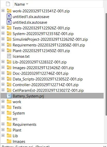
Now select Tests -> system -> BMS closed loop harness dashboard
it will open the simulink model of BMS_closedloop_Harness_dashboard
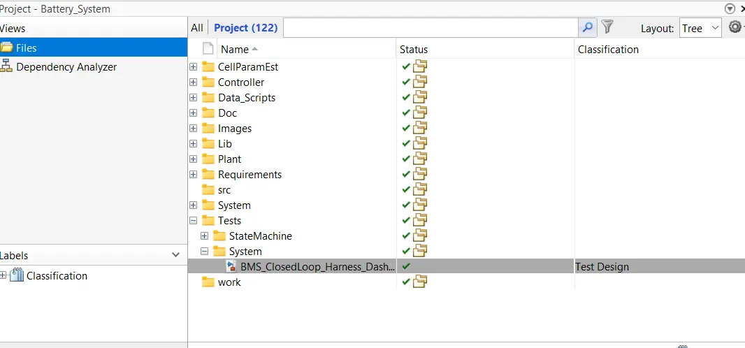
After opening it you will get 2 models
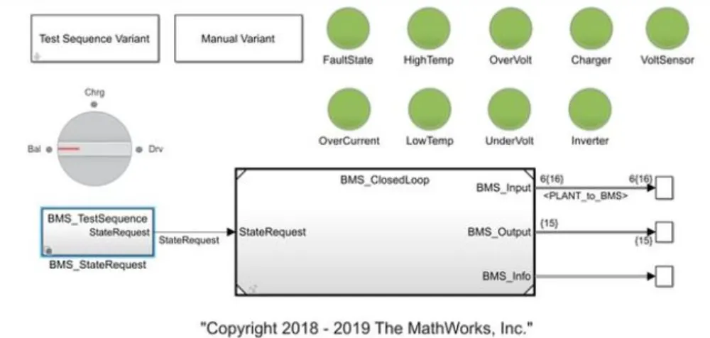
1) BMS CLOSED LOOP HARNESS DASHBOARD
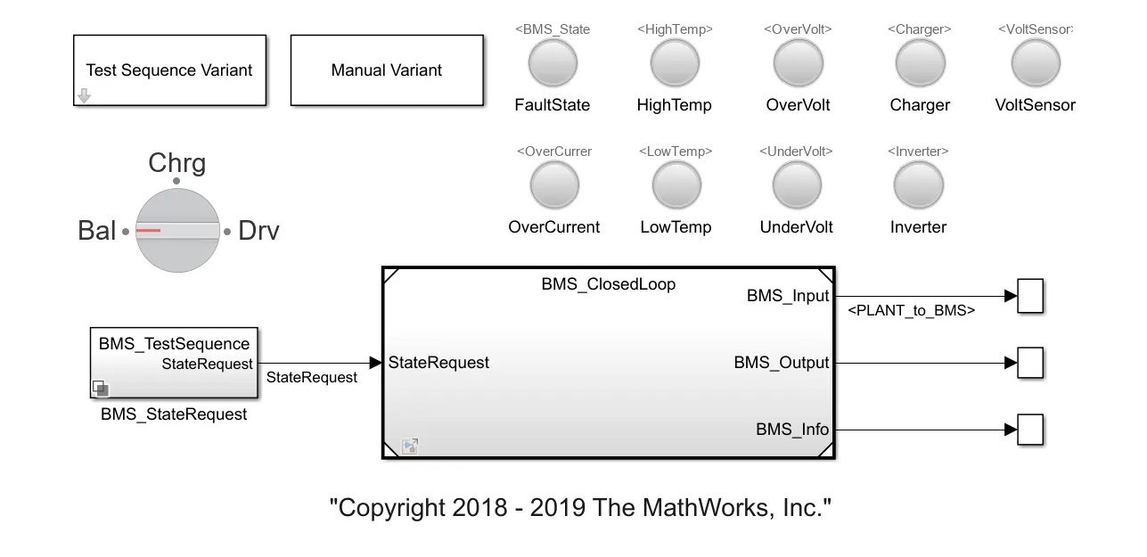
Subsystem 1 - Test Sequence Variant: Within this subsystem, you will find three distinct test sequences. It allows for the selection of the required test sequence from these options.
Subsystem 2 - Manual Variant: When this block is active, the choice of the test sequence becomes a manual process. A rotary switch with three conditions (battery, charging, and driving) is utilized to manually select the desired sequence.
BMS state request is the subsystem which is the request input to the BMS closed loop which gives which test sequence is selected whether it is automatic test sequence or manual selected sequence.
Indicator lamps are present to display various states and potential faults related to a battery. These states include High Temperature, Overvoltage, Charger status, Voltage Sensor readings, Overcurrent, Low Temperature, Under Voltage, and the Inverter state. A green light signifies that all these states are within acceptable parameters, indicating that the battery is in good condition for both charging and discharging. Conversely, a red indication signals the presence of a fault state.
2) BMS CLOSED LOOP
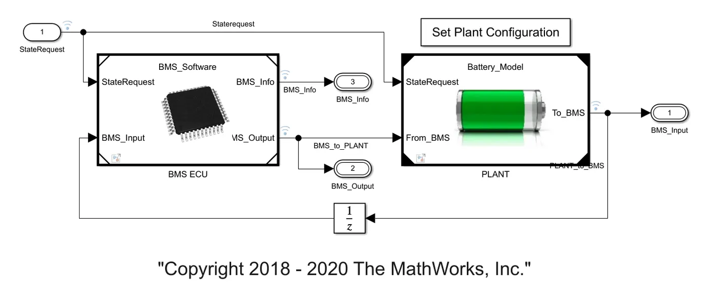
BMS ECU
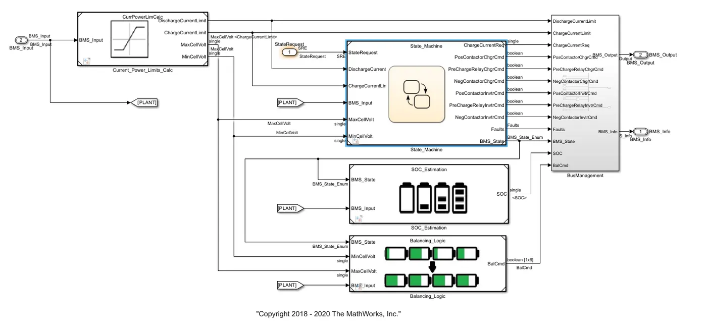
is the software like unit which controls,protects,balance and manage the battery,
It consists of following subsystems
current power limits calculation:
This block controls and calculate the charge current limit,discharge current limit.min voltage of cell and max voltage of cell.
state machine:
This is state machine, which gets the input from the state request,based on the state request state machine goes through the logic of charging,discharging,balancing by open the contactors of the battery,inverter and monitor the fault states and give the BMS output.
SOC estimation:
SOC is accurately estimated by coulomb counting and using the Kalman filters,
Balancing logic:
This is the subsystem which consist of state machine which will balance the cell according to the BMS state,It will activate balacing or deactivate the balancing according to the BMS state requirements.
TEST CASE FOLLOWED
Click on test sequence variant and select 1, 2, or 3 for differentt sequence
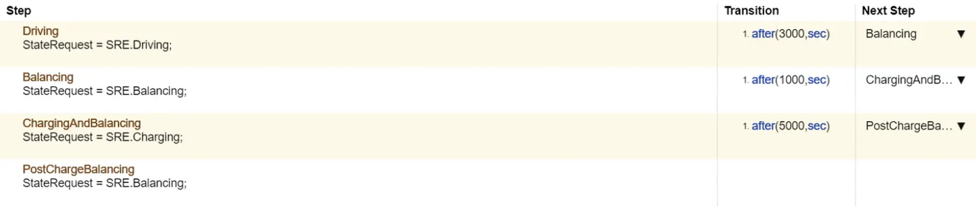
SEQUENCE 1:
This test case has three operating states of the BMS in it: driving, charging and standby.
OUTPUT:
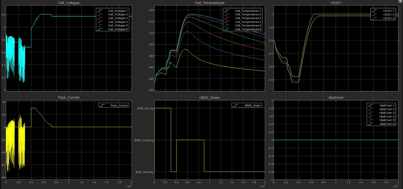
we can see that for the first few seconds the battery was undergoing discharging and some charging due to regenerative braking. later when the pack was charged, we can see that the battery voltage rised to 4.2V while the cell temperature also rised rapidly ans the SOC kept on increasing till the battery gets fully charged.
SEQUENCE 2:
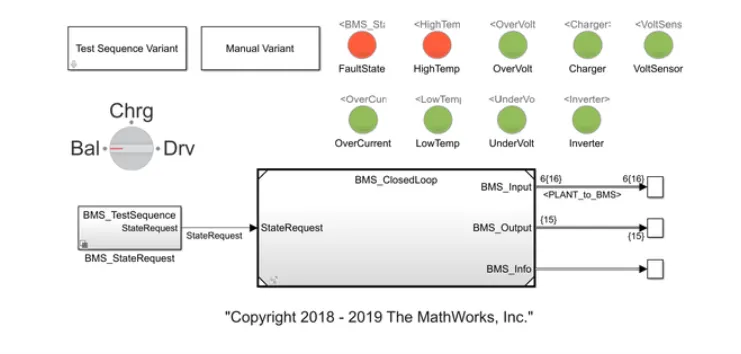
there is 2 states, the driving and charging state. As the temperature increases during charging, the BMS enters into the fault mode.

OUTPUT:
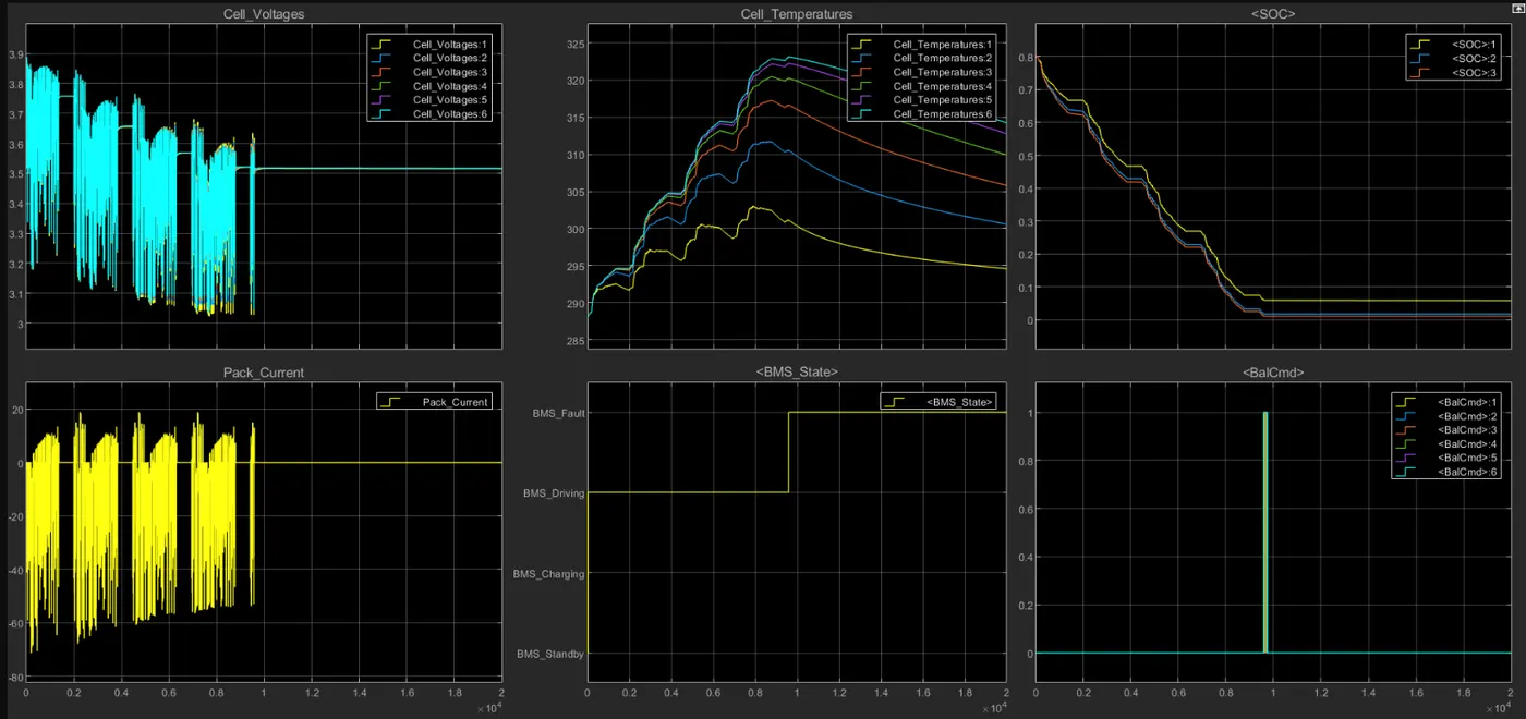
we can see that after the fault condition the battery gets disconnected and no further charging takes place
SEQUENCE 3:
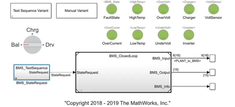
his test case has only the charging state. The BMS system charges the load initially. As, there is no transition after the charging state, the BMS system remains connected in the charging state albeit without the transfer of charge

OUTPUT:
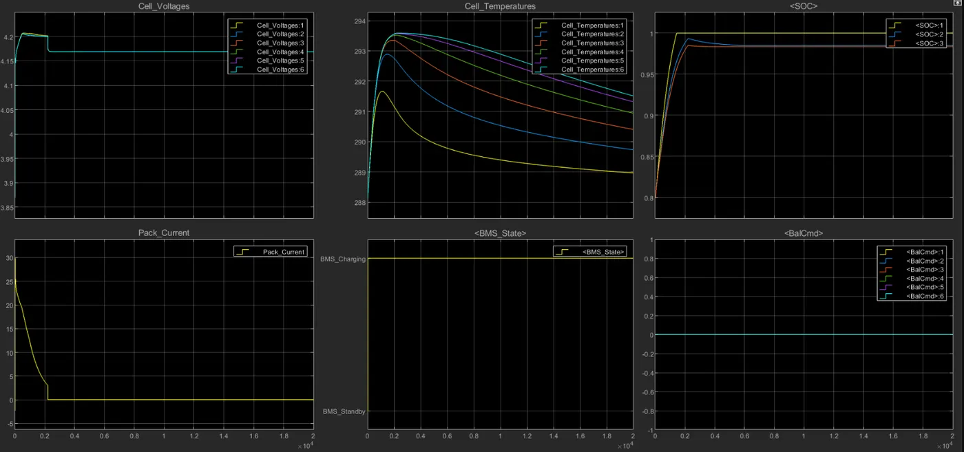
Here we see the SOC increase from 80% to 100% and remains unchanged
2.What is coulomb counting? Refer to the above model and explain how BMS implements coulomb counting for SOC estimation ?
Hint :(Download the file from the link and go to SOC estimation model-ECU block)
Ans:
COULUMB COUNTING:
Coulomb counting is a method employed to monitor the state of charge of a battery pack. It functions by integrating the active current flow (measured in amperes) over a period to determine the total energy entering or leaving the battery pack, resulting in a capacity typically measured in ampere-hours (Ah).
COULUMB COUNTING METHOD:
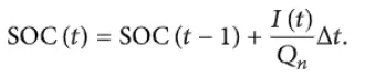
The Coulomb counting method, also known as the battery current integration method, entails measuring and integrating the charging or discharging current, denoted as I(t), over time to calculate the remaining energy inside the battery. In this method, the state of charge (SOC) at the previous time step (SOC(t-1)) is utilized, and the energy added or removed in the current time step is added to or subtracted from SOC(t-1) to ascertain the energy present in the battery at the current moment.
The SOC estimation in the Coulomb counting method is determined by the following equation:
It's important to note that while the Coulomb counting method is accurate and reliable, it does not account for factors such as discharge rate, temperature, hysteresis, battery age, and other variables
EQUATION IMPLEMENTED IN MODEL:
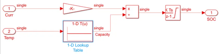
Two inputs current and temperature of the pack are provided. Current is converted to capacity (Ah) by dividing with 3600. Then based on the temperature the pack capacity is estimated. This estimated capacity is divided by the discharge capacity and integrated over time which gives the SoC at any given instant.