Week 7 State of charge estimation
1)Simulate the 3 test cases from harness dashboard from matlab
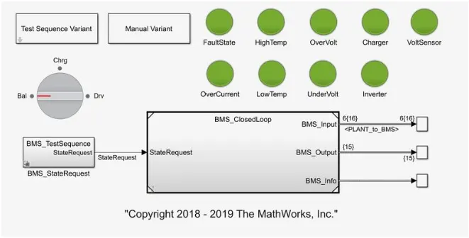
to simulate the harness model we have to select the file from the project file after selecting the BMS closedloop and test ahrness dashbord file has open
then to test the file for the 3 varients we can choose the test sequences randomly
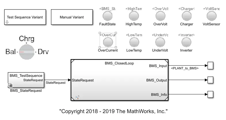
after run the model for the 3 sequences we get the result were
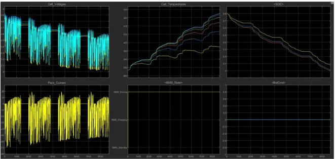
for sequence 1 which has been run to get the results shown as the while the battery of the vehicle at charging and driving state we can able to seaa that the temperature and current keeps increasing and SOC were decreasing due to decresing charge amt and while vehicle at standby mode the SOC are stable and the temperature keeps decreasing
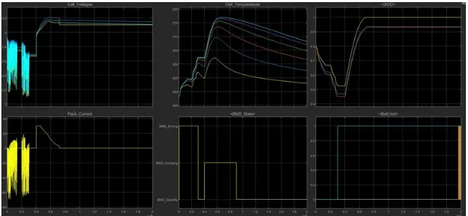
for varient 3 the graph show for the states of charging while vehicle at standby temperature keeps zero and SOC are also zero at standby and while charging soc has increases due to charging of the battery and temperature also keeps increasing
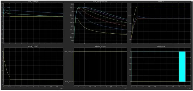
for varient 2 for this varient has shown graph at driving while driving the temperature keeps increases and maintain stable while the current and voltages maintain constant and SOC are keeps decrease because of drive state
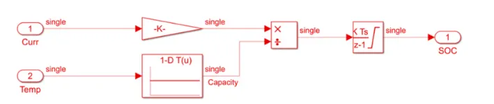
2)What is coulomb counting?Refer to the above model and explain how BMS implements coulomb counting for SOC estimation ?
The Coulomb counting method measures the discharging current of a battery and integrates the discharging current over time in order to estimate SOC [20]. Coulomb counting method is done to estimate the , which is estimated from the discharging current, , and previously estimated SOC values, . SOC is calculated by the equation of SOC(t) = SOC(t-1)+I(t)/Qn*deltaT
Modified Coulomb Counting Method
To improve the Coulomb counting method, a new technique called modified Coulomb counting method is proposed. The modified Coulomb counting method uses the corrected current to improve the accuracy of estimation.
The corrected current is the function of discharging current. There is a quadratic relationship between the corrected current and discharging current of battery. By practice of experimental data, corrected current is calculated
Ic(t) =K2*I(t)^2+K1*I(t)+k0
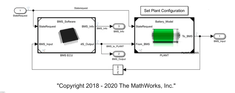
At BMS model the state request and BMS input were given as input for ECU subsystem
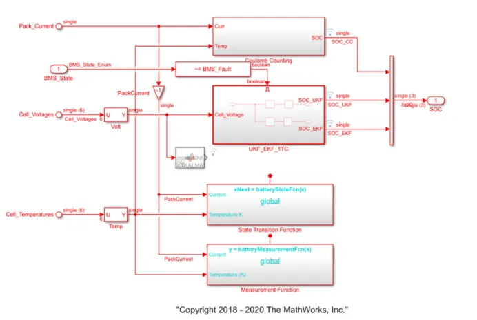
while at the coloumb counting the current and temperature were given as input and the SOC are the output for the BUS management to plot