Week 7 State of charge estimation
Q1.
OBJECTIVES : We have to simulate 3 test cases from harness dashboard and write a detail report on the results.
How BMS implements coulomb counting for SOC estimation.
Lithium ion battery management system
Lithium ion battery packs are the widely used energy storage system in electric vehicles. The battery management system (BMS) is responsible for safe operation, performance and battery life under diversre charge-discharge and environmental conditions. When designing a BMS the cell voltage and the temperature, state of charge,state of health and the charging profile has to be controlled and maintained.
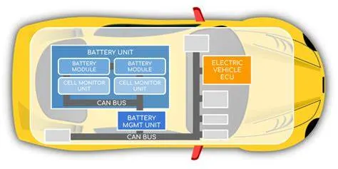
Also, it indicates whether there has been a fault, for example that any cell has reached an over-temperature condition or under-voltage condition (Undervoltage occurs when the avarage voltage of a system drops below intended levels. It is usually caused by undersized and overloaded utility).
Close loop BMS system using this link-
Through this link we test all 3 cases from Harness dashboard.
After downloading the model and extracting all the zip file in the system and set all the file that we need to test all 3 cases from harness dashboard.
After opening the BMS system we have to go for the harness dashboard.This dashboard can be selected from the MATLAB window. And go inside the battery system 2020 version.
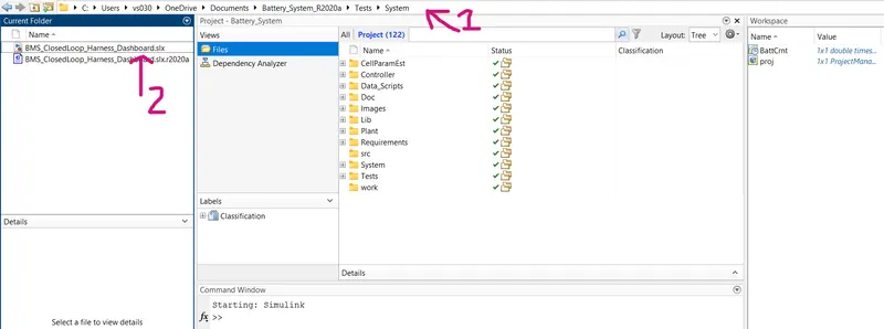
There are procedure of opening the Harness models from Battery system R2020a.
Battery system R2020a > test > system > BMS_CloseLoop_Harness_Dashboard.slx
MODEL :
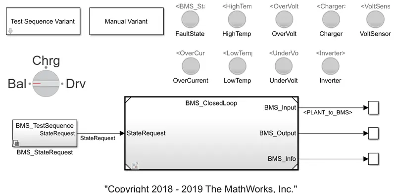
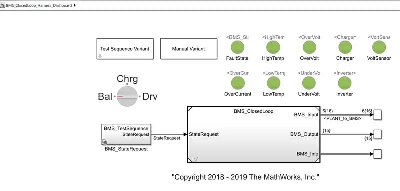
The harness dashboard is shown below. It consists of the test sequence varient subsystem which hold a three different test cases. This dashboard also helps in determining the fault states and other parameters as shown in the diagram below. Green color indicates that the system is working without any errors while red signal will indicate that there is a fault in the system.
Test case 1
To check the faults in the system we have to go inside the Test Sequence Varient. Here, the first compilation the test case 1 is selected.
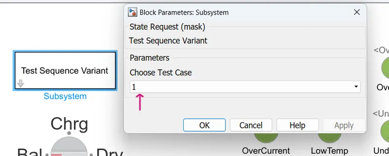
After applying the selected test case, we have to run the model and after simulation, dashboard shows there is no error and faults.
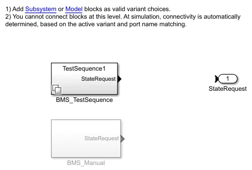
If we click on "BMS_stateRequest" the following system open up. Now we have to select "BMS_TestSequence".
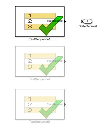
Selecting the first sequence we can check the condition for the particular condition.
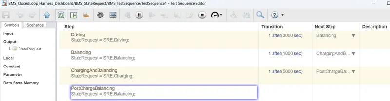
There are three steps of driving condition, namely-
- Driving
- Charging
- Balancing
When the simulation begins, intially the vehicle is in driving state, and SOC will decrease for this time period. After a time period of 3000s the next step is balancing mode and the vehicle is in standby condition.After another 1000s, the vehicle is in charging phase and the battery's SOC increases almost to 100%. The next phase is the postcharging phase in which the vehicle again goes for the standby mode.
The scope shows the following result for the test case 1.
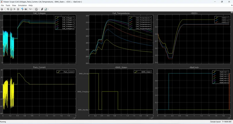
From the scope results we can define note the following points.
- The input cycle can be seen in the BMS_state plot in which the vehicle initially undergoes driving, then charging till SOC = 90% and then later in standby state.
- During charging the battery pack voltage increase upto 4.2V.
- The cell temperature increases during the driving and charging cycle and start falling off in standby mode.
- The SOC drop to less than 50% after the driving cycle and then later put into charging untill SOC reaches 100%.
- The current supplied to the EV during driving phase can be seen in the current plot. Initially 3000s it get fluctuated but after 6000s, current settle down at 0.
Test case 2
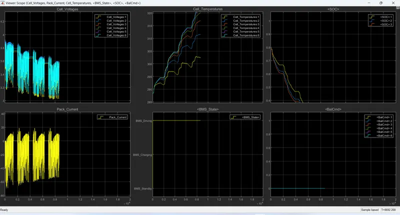
Now we will go for the second test case. For this we have to go to test case varient subsystem and select test case 2 from there and click on "OK". Then we have to run the system for the given simulation time. The result shows that there is a fault condition in the vehicle. It simulate only 8692s insteed of 20000s.
If we click on "BMS_stateRequest" the following system open up. Now we have to select "BMS_TestSequence".
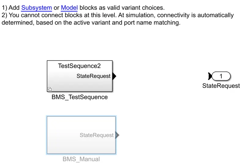
Selecting the first sequence we can check the condition for the particular condition.
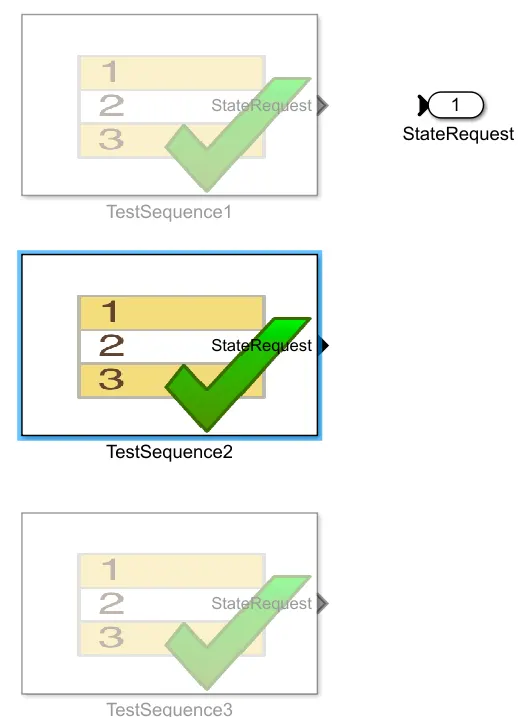
This test case has two phase for the battery pack. i.e driving and charging phase.
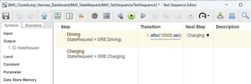
The Scope shows the various parameter for the BMS model under 2 test case. After 10000 seconds when the driving cycle is over(even it not cross 8692 sec.) the fault condition occurs and the SOC does not increase even for the charging phase.
Test case 3
The last case is for the third case sequence. For this we have to go in test case varient and select test case 3 from that and click "OK". After applying the select test case 3. we have to run the simulation. The dashboard shows there is no error and faults.
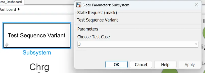
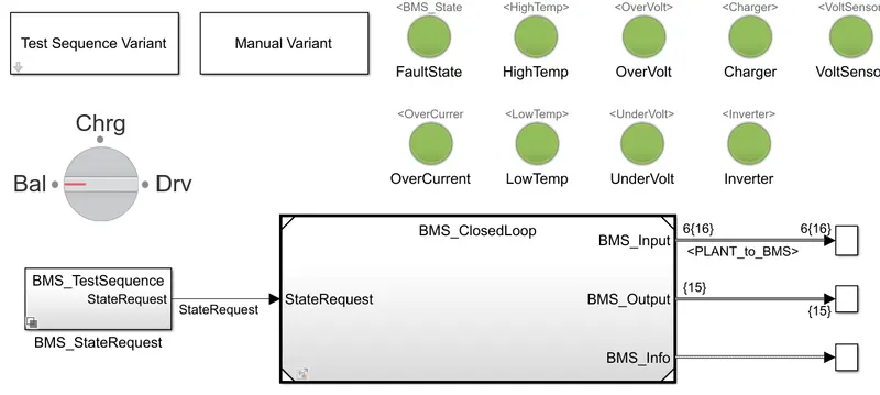
If we click on "BMS_stateRequest" the following system open up. Now we have to select "BMS_TestSequence". And Selecting the first sequence we can check the condition for the particular condition.
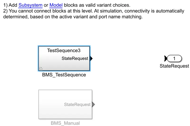
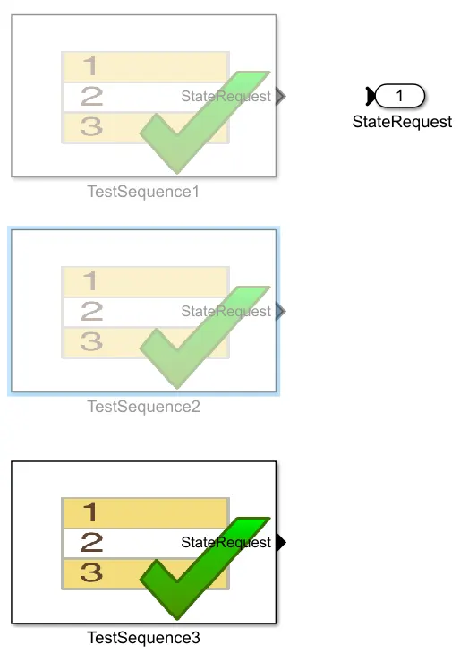
There is only one single phase here for the third test case i.e the charging phase.

The scope shows the result for the third test case.Here the SOC increase from 80 to 100% and then remains in standby mode.
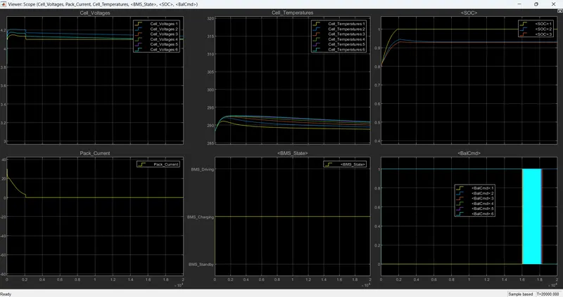
From the scope results we can define note the following points.
- The input cycle can be seen in the BMS_state plot in which the vehicle initially charging till SOC = 100% and then later in standby state.
- During charging the battery pack voltage increase upto 4.2V but after 2000 second there are little bit deep in voltage.
- The cell temperature increases during the charging cycle and start falling off in standby mode.
- The current supplied to the EV during driving phase can be seen in the current plot. we see in plot initially some increament in current but after 2000 seconds it go with standby mode.
----------------------------------------------------------------------------------------------------
Q2.
Coulomb counting and BMS implements coulomb counting for SOC estimation.
State of charge (SOC) :
The state of charge (SOC) is a measurement of the amount of energy available in a battery at a specific point in time, expressed as in percentage. For example, the SOC reading for a computer might read 95% or 100%.
The determination of battery SOC is always an essential part of a BMS. The accurate and reliable estimation of battery SOC can provide a necessary assessment factor for vehicle energy management and optimal design of the control system. Therefore, a larger number of methods have been proposed for estimating battery SOC in real-time. Here we are calculating state estimation by using the Coulomb Counting Method.
Coulomb counting method:
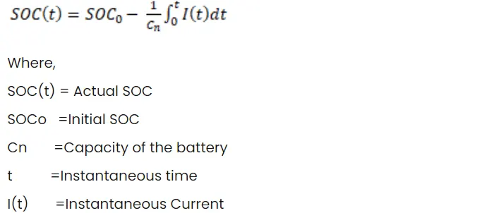
The Coulomb counting method measures the discharging current of a battery and integrates the discharging current over time in order to estimate SOC. Coulomb counting method is done to estimate the SOC values, which is estimated from the discharging current and previously estimated SOC values, SOC is calculated by the following equation:
For the BMS model using Coulomb counting for SOC estimation
First we have to open the BMS closeloop model to see SOC estimation block.
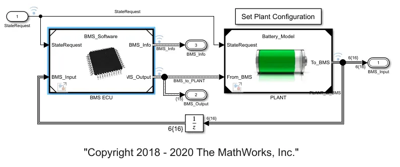
Now double click on BMS ECU block to see SOC estimation.
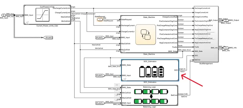
We have to open SOC estimation and go to inside the coulomb counting.
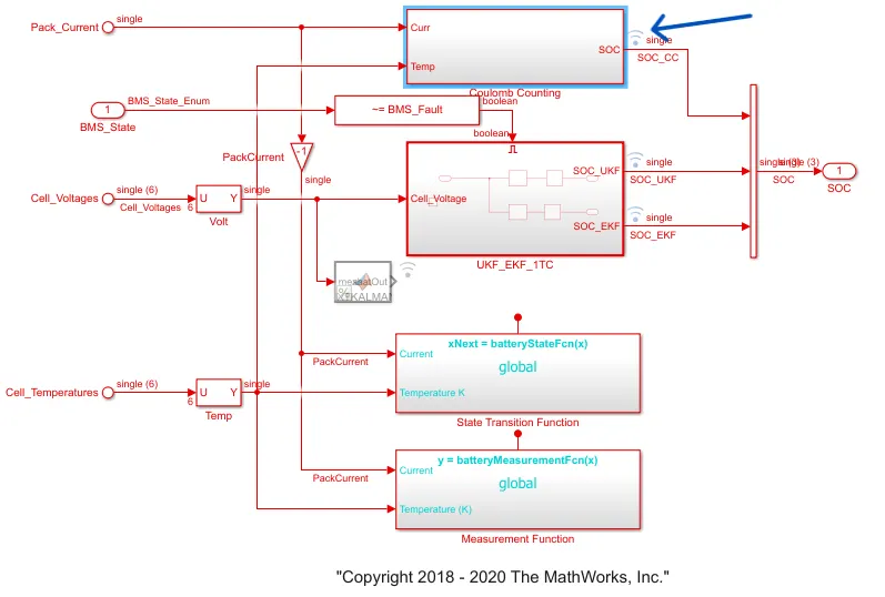
Using coulomb counting for SOC estimation.
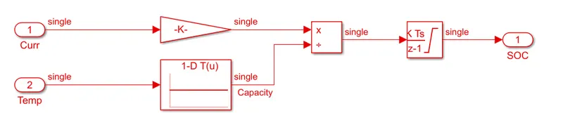
Model Explaination :
- To see the SOC estimation we have to follow some step to go there [Open BMS ECU > SOC_estimation >Coulomb counting].
- This system does the estimation by coulomb counting equation mentioned above.
- Advantage of coulomb counting method is its simplicity and low computational cost.
- Temperature and current from the battery is given as inputs.
- Current signal is given to a gain block and temperature is given to capacity since it varies according to temperature.
- These inputs are given for integration where current will be integrated with respect to time.
- This output is given to another block where it is divided by capacity.
- Here we see the current integrated with time through a discrearte integrator along with the temperature to get the idea about SOC.
- Hence the SOC is estimated.
CONCLUSION :
- Here we test all 3 test cases for the harness dashboard. Where first cases difines there is no error and faults but in 2 cases there are error in temperature indicator as we also see through indicator dashbaord.
- And deifine how BMS implements coulomb counting for SOC estimation.