Week 7 State of charge estimation
Battery management systems:-
Battery management system is a electrical-electronic device that regulates the voltage , SOC , SOH ,Current of the battery pack. it avoids the damages cause due to over voltage and over current conditions , it also protects the battery pack from themal overshoots.
It indicates fault in a battery pack . if any cell of a battery reaches to over temperature or over current,or over voltage it shows faults
BMS is a electronic circuit board mounted over the battery and connected to the cells.


Importance of BMS in Battery pack
1)BMS protects battery against over temperature , over current, over voltage
2)It indicates state of charge by columb counting method
3)It also indicates the state of health of a battery
4)it is quite risky to use battery without BMS as it will roise the fire hazard and explosion of cells.
Simulation of BMS useing matlab project
use the link to download the zip file 'Battery manangement"

Extract the file to desktop
right click on the folder and then extract all

select the destination as desktop
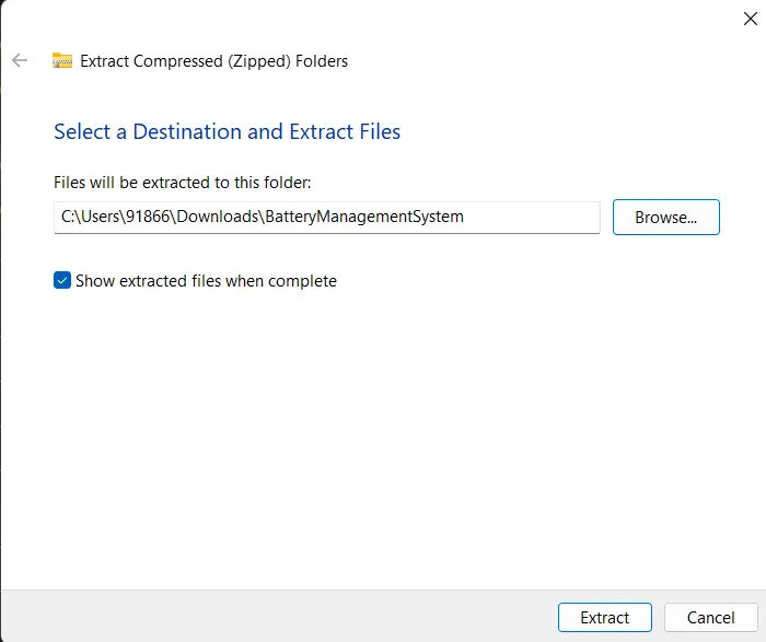
click on extract
search for battery model .slx
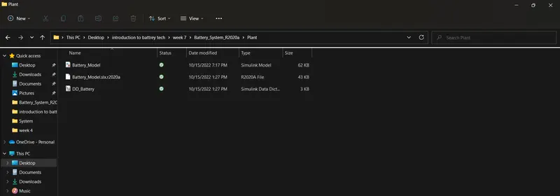
click on it below window will get open
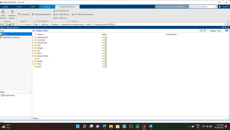
click on test
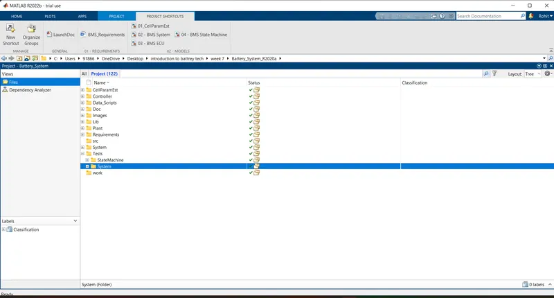
click on system
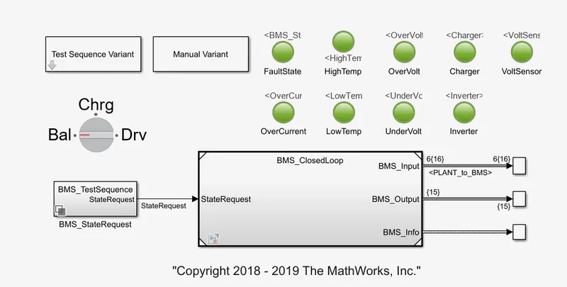
open the BMS_ closed loop harness dashboard
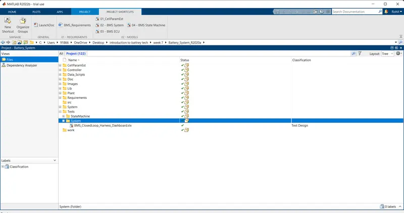
After clicking on to the tab the below simulation window will be open.
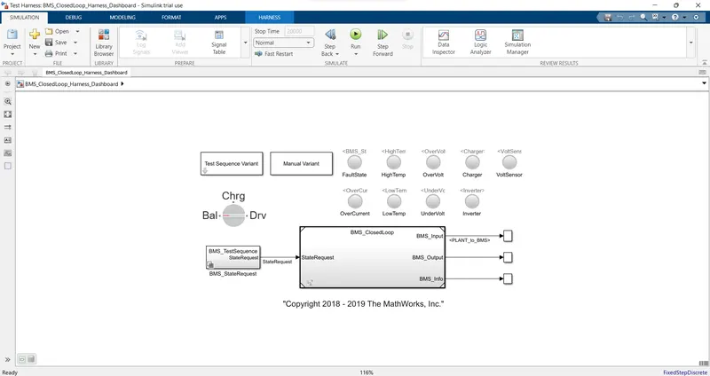
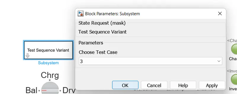
Click on test sequence variant and select it as 3
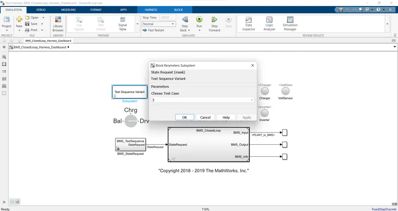
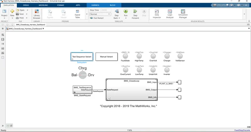
run the simulation to obtain results.
Case 1.
we have to check for fault , change the Test Sequence variant to 1
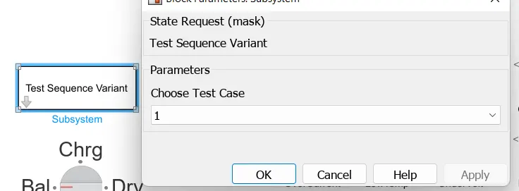
after applying the changes we have to run the simulation,the dashboard shows no errors.
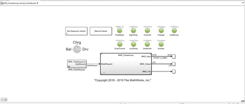
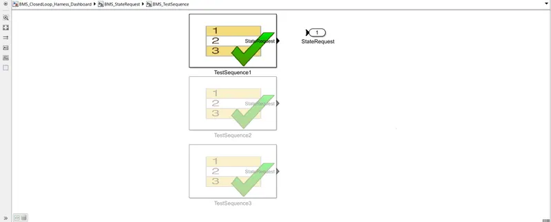
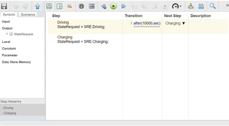
If we click on to the BMS_Test sequence following windows get open

selecting the first test sequence we can codition for specific condition
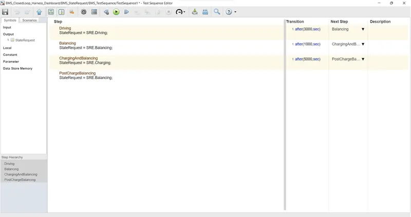
there are 3 types of conditions
1)Driveing
2)chargeing
3)dischargeing
till 3000 seconds vehicle is dischargeingat this stage SOC is decreasing and after 3000 seconds battery undergoes balenceing state and vehicle is in standby condition After another 1000 seconds vehicle is in chargeing state thus SOC increases upto 100% the next phase is post chargeing phase at which vehicle is in standby state
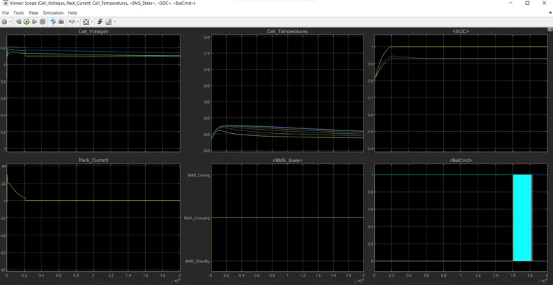
The simulation results are as follows
1)From the BMS_State plot vehicle initially undergoes driveing, then chargeing till SOC =90% and then later standby state
2)Dureing chargeing the battery pack voltage is increased upto 4.2V
3)Cell temperatures incres=ases dureing the driveing and chargeing cycle and starts falling in standby mode
4)The SOC drops to less than 50% after the driveing cycle and then later put into chargeing until SOC reaches 100%
5)The current supplied to EV dureing driveing phase can be seen in current plot
CASE NO 2
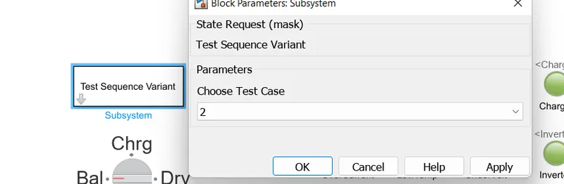
For this test click on test sequence variant and change the test case to 2 , click on ok
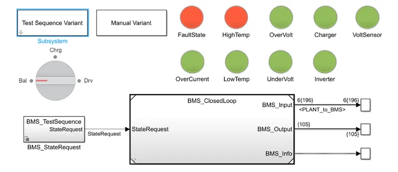
start simulation by clicking on to the Run
The result shows that there is a fault in a system and model depects red colour.
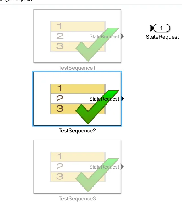
To see the diffrent Test sequence click on the BMS_Test Sequence the following window will get open click on it
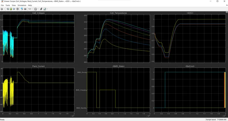
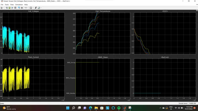
The scope shows the various parameters for BMS model under second test case . After 10000 seconds when driveing cycle is over fault condition occures and So SOC does not increase even for the chargeing phase
Case No 3
change the Test Sequence Variant to 3 then click on ok
Run the simulation and get the fault conditions and Results
No fault is occured on the BMS dashboard
Results of simulation are as follows.
Conclusion
In this way we have simulated 3 test cases of the BMS
Columb Counting method
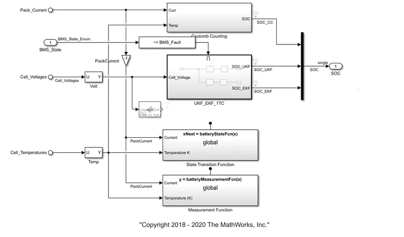
The state of charge is a measurement of the amount of energy available in a battery at a specific point in time expressed as a percentage
The estimation of battery SOC is always an essantial part of BMS .The accurate estimation of SOC can provide a necessary factor for vehicle energy management and optimal design of a control system.
Columb Counting method
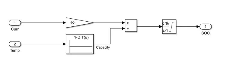
Columb counting method measures the dischargeing current of a battery and intigrates the dischargeing current over time in order to estimate SOC. Columb counting method is used to estimate the SOC values,which is estimated by discharge current and previously estimated SOC values,
SOC is calculated by the following equation

where
SOC(t)=Actual SOC
SOC =initial soc
Cn= capacity of a battery
t = instantaneous time
I(t) = Instantaneous current