Week 7 State of charge estimation
Objectives:-
1.Simulate the 3 test cases from harness dashboard and write a detailed report on the results
2.What is coulomb counting? Refer to the above model and explain how BMS implements coulomb counting for SOC estimation ?
Solution#1:-
What is a Battery Management System?
Definition
Battery management system (BMS) is technology dedicated to the oversight of a battery pack, which is an assembly of battery cells, electrically organized in a row x column matrix configuration to enable delivery of targeted range of voltage and current for a duration of time against expected load scenarios. The oversight that a BMS provides usually includes:
- Monitoring the battery
- Providing battery protection
- Estimating the battery’s operational state
- Continually optimizing battery performance
- Reporting operational status to external devices
Here, the term “battery” implies the entire pack; however, the monitoring and control functions are specifically applied to individual cells, or groups of cells called modules in the overall battery pack assembly. Lithium-ion rechargeable cells have the highest energy density and are the standard choice for battery packs for many consumer products, from laptops to electric vehicles. While they perform superbly, they can be rather unforgiving if operated outside a generally tight safe operating area (SOA), with outcomes ranging from compromising the battery performance to outright dangerous consequences. The BMS certainly has a challenging job description, and its overall complexity and oversight outreach may span many disciplines such as electrical, digital, control, thermal, and hydraulic.
The Benefits of Battery Management Systems
An entire battery energy storage system, often referred to as BESS, could be made up of tens, hundreds, or even thousands of lithium-ion cells strategically packed together, depending on the application. These systems may have a voltage rating of less than 100V, but could be as high as 800V, with pack supply currents ranging as high as 300A or more. Any mismanagement of a high voltage pack could trigger a life-threatening, catastrophic disaster. Consequently, therefore BMSs are absolutely critical to ensure safe operation. The benefits of BMSs can be summarized as follows.
- Functional Safety. Hands down, for large format lithium-ion battery packs, this is particularly prudent and essential. But even smaller formats used in, say, laptops, have been known to catch fire and cause enormous damage. Personal safety of users of products that incorporate lithium-ion powered systems leaves little room for battery management error.
- Life Span and Reliability. Battery pack protection management, electrical and thermal, ensures that all the cells are all used within declared SOA requirements. This delicate oversight ensures the cells are taken care of against aggressive usage and fast charging and discharging cycling, and inevitably results in a stable system that will potentially provide many years of reliable service.
- Performance and Range. BMS battery pack capacity management, where cell-to-cell balancing is employed to equalize the SOC of adjacent cells across the pack assembly, allows optimum battery capacity to be realized. Without this BMS feature to account for variations in self-discharge, charge/discharge cycling, temperature effects, and general aging, a battery pack could eventually render itself useless.
- Diagnostics, Data Collection, and External Communication. Oversight tasks include continuous monitoring of all battery cells, where data logging can be used by itself for diagnostics, but is often purposed to the task for computation to estimate the SOC of all cells in the assembly. This information is leveraged for balancing algorithms, but collectively can be relayed to external devices and displays to indicate the resident energy available, estimate expected range or range/lifetime based on current usage, and provide the state of health of the battery pack.
- Cost and Warranty Reduction. The introduction of a BMS into a BESS adds costs, and battery packs are expensive and potentially hazardous. The more complicated the system, the higher the safety requirements, resulting in the need for more BMS oversight presence. But the protection and preventive maintenance of a BMS regarding functional safety, lifespan and reliability, performance and range, diagnostics, etc. guarantees that it will drive down overall costs, including those related to the warranty.
Battery management system Models:-
BMS closed Loop Harness Dashboard:-
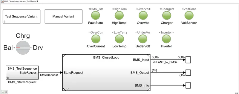
Explanation of models :-
1. Test Sequence Variant:- In this type of block to used for to test the different case and gives to different results at BMS.
2. Manual Variant:- This variant is nothing but in which have a subsystem.
3. Rotary Switch Block:- Set value to tune parameters or variables. Tht is Balancing, charging, and Driving.
4. BMS State Request:- It is mainly depend upon the test sequenxe variant.
It is to change the test case then change it the state requeat in BMS state request block.
5. Lamp Block:- Their have certain lamp block it is Fault state, High Temp., Over Volt, Charge, Volt Sensor, OverCurrent, Low Temp, UnderVolt, Inverter,
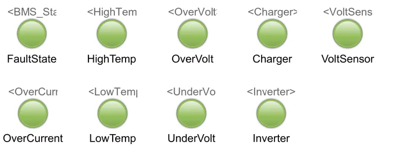
A. In which they all are green in the sense their have no fault.
B. Then we have to run the system to Simulation time. The result show the fault condition in the Vehicle. The dashboard in the model shows depicts a same with a red colour indication.
BMS Closed loop:-
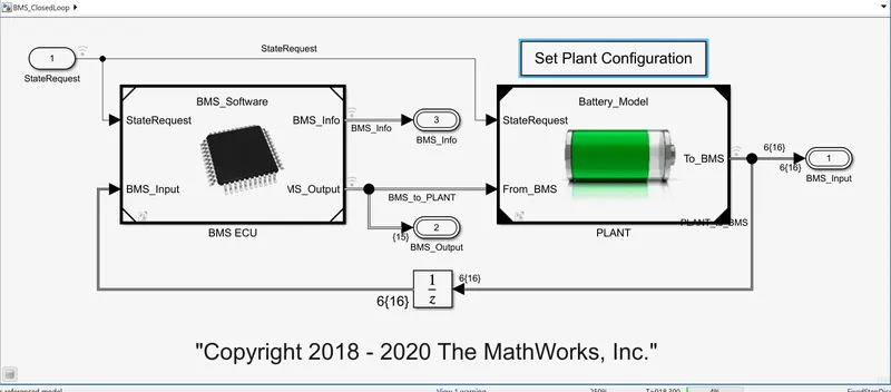
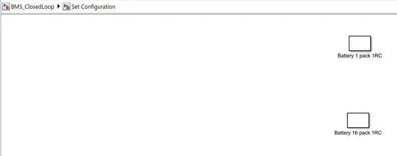
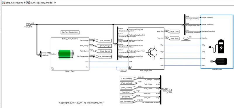
1. Set Plant Configuration:-
Click on 'Battery 1 Pack 1Rc' It means to activate the 6 cell battery pack.
The other option have 'Battery 16 1Rc' It means to activate the 16 cell connection.
2. Plant:- In Plant have battery pack, pre charge converter and have charge load.
In charger load have charger and inverter have charger(+)(-) and inverter(+)(-) connection.
And over all plant calculate the Cell voltage, Pack current, Pack Voltage, Vout Charger, Vout Inverter, Cell Temperature values.
3. BMS ECU(BMS Software):-
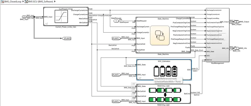
In which have Current power limit to give the limit data to the State machine, and it is attach to the SOC estimation, And Balancing logic block, They all are connect to Business management and give output,
In State machine they have State request, Charge current, discharge current, BMS input, Max cell volt, min cell Volt.
Results of Harness Dashboard:-
In Test Sequence 1:-
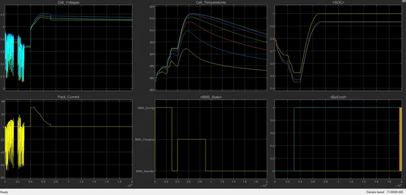
From the Scope we can define :-
1) The input cycle can be seen in the BMS_state plot the vehicle is initially driving then charging till SOC= 90% and then later in Standby state
2) During charging the battery pack volatge will reach to the 4.2V.
3) The Cell Temperature is increasing in driving and charging cycle and start falling during stand by mode.
4) The SOC is drop to less then 50% after the driving cycle and then put in charging until SOC reaches the 100%.
5) The current supplied in the EV during driving phase. It will initially increase and decrease and high is about 30 and approx. and then in standby condition it will be constant can be seen in the current plot.
In Test Sequence 2:-
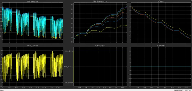
From the Scope we can define :-
1) the cell voltage fluctuates from 3.9 volts to 3.2 volts repeatedly as seen in graph of cell voltages.
2)the battery pack current fluctuates from 0 to -60A and then rises to 10 A repeatedly as shown.
3)the cell temperature increases as there is driving stage from 0 to 10000 seconds.
4)as driving stage is there from 0 to 10000 sconds ,thus BMS graph shows the BMS driving .
5) the SOC continue to reduce from 80% to 0% . the SOC do not increase beacuse there is no charging and balancing stage.
though the driving stage is till 10000 seconds but as battery completly discharges at 9000 seconds (as SOC is 0% at 9000 seconds) thus vehicle runs till 9000 seconds only.
In Test Sequence 3:-
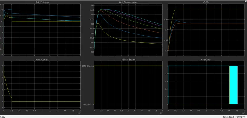
From the Scope we can define :-
1) the cell voltage varies till 20000 seconds and then remians constant
2) at start the pack current increses to 30A and then reduce to 0 A at 2000 seconds and then remains constant at 0 A.
3) cell tempearture varies as shown in the graph.
4) as there is only charging stage , thus BMS graph shows BMS charging .
5)as only charging takes place.
thus SOC was 80% at first , then SOC increases to 100% in 2000 seconds then SOC remains constant at 100%
Solution#2:-
Couloumb Counting:-
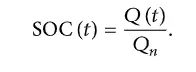
The SOC is one of the most important parameters for batteries. In general, the SOC of a battery is defined as the ratio of its current capacity (Q(t)) to the nominal capacity (Qn). The nominal capacity is given by the manufacturer and represents the maximum amount of charge that can be stored in the battery. The SOC can be defined as follows:
The various mathematical methods of estimation are classified according to methodology. The classification of these SOC estimation methods is divided into the following four categories.
(i)Direct measurement: this method uses physical battery properties, such as the voltage and impedance of the battery.
(ii)Book-keeping estimation: this method uses discharging current as the input and integrates the discharging current over time to calculate the SOC.
(iii)Adaptive systems: the adaptive systems are self-designing and can automatically adjust the SOC for different discharging conditions. Various new adaptive systems for SOC estimation have been developed.
(iv)Hybrid methods: the hybrid models benefit from the advantages of each SOC estimation method and allow a globally optimal estimation performance. The literature shows that the hybrid methods generally produce good estimation of SOC, compared to individual methods
SOC:- The state of charge (SOC) is a measurement of the amount of energy available in a battery at aspecific point in time expressed as a percentage. for example, the SOC reading for a computer might read 95% or 100%.
`SOC(t) =1/cintI(p)dt`
Where
C = Total capacity of the battery
I = Current
SOC Estimation:-
The determination of battery SOC is always an essential part of a BMS. The accurate and relaiable estimation of battery SOC can provide a necessary assessment factor for vehicle energy management and optimal design of the control system. Therefore, a larger number of methods have been proposed for estimating battery SOC in real-time. Here we are calculating sate estimation by using the Couloumb Counting method.
Couloumb Counting method:-
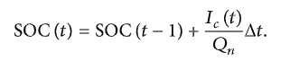
The couloumb counting method measures the discharging currengt of a battery and integrates the discharging current over time in order to estimate SOC. Couloumb counting method is done to estimate the SOC values, which is estimated from the discharging current and previously estimated SOC values, SOC is calculated by the following equation.
`SOC(t) = SOC(t-1)+(I(t))/(Qn)Deltat.`
Modified Coulomb counting method
To improve the Coulomb counting method, a new technique called modified Coulomb counting method is proposed. The modified Coulomb counting method uses the corrected current to improve the accuracy of estimation.
The corrected current is the function of discharging current. There is a quadratic relationship between the corrected current and discharging current of battery. By practice of experimental data, corrected current is calculated by the following form:

where , k2, k1, k0 are constant values obtained from the practice experimental data.
In modified Coulomb counting method, SOC is calculated by the following equation:
The experimental results show that the accuracy of the modified Coulomb counting method is superior to the conventional Coulomb counting method.
BMS_ECU (BMS_Softwaare):-
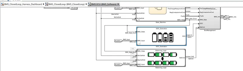
The BMS_closedloop_Harness_Dashboard have BMS ECU(BMS_software) double click on it.
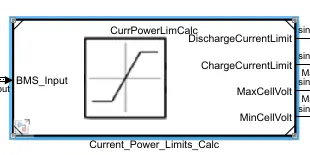
by clicking on the current power limit calc block , we get the below block diagram.
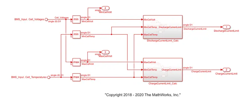
here the cell voltage and cell temperature is used to decide maximum allowable charging and discharging current limits.
when cell is at lowest SOC , its voltage is low,and thus it is important to prevent cell from delivering large amount of current because it wil cause large voltage drop that could be potential below the cut off voltage specify by the cell manufacture.
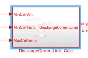
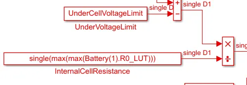
click on dischargecurrentlimit calc block, we get the following block diagram shown below,
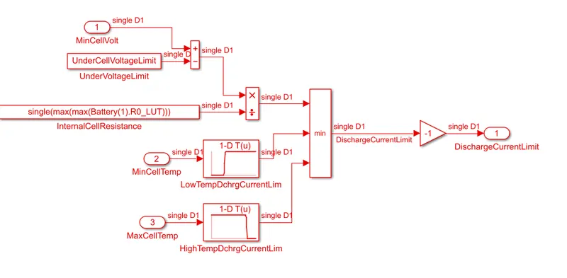
here by comparing the minimum cell voltage in the module against this lowest threshold voltage and then divided by maximum internal cell resistance value, , we can compute the voltage based threshold.
it is also important to limit the current delivery and current intake when temperature is too high or too low.
using the lockup table with rising and falling s shape profile, we can specify current threshold based temperature and thus can modulate allowable current delivery.
it is recommended to avoid low and high temperature during discharging and low temperature during charging.
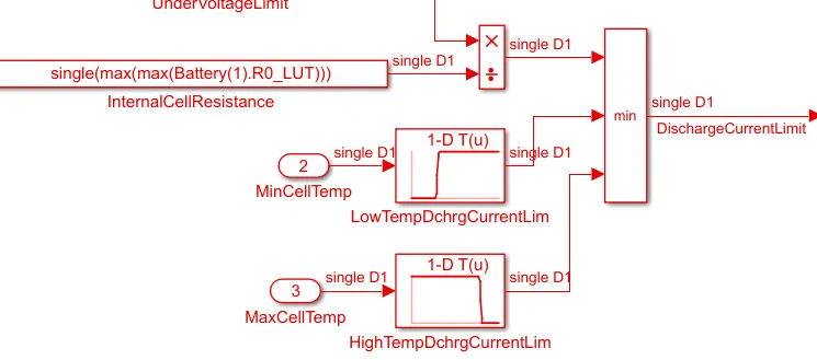
then the above two threshold are then compared and minimum of this two becomes the current limit.
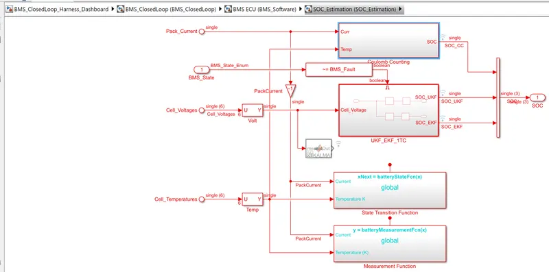
knowing how much longer we can able to drive our car before we had to stop for recharge depends on the accurate estimation of battery SOC.
In battery system , we do not measure SOC directly , we actually measure something else and then relate it with SOC.
In BMS ECU block have SOC_estimation block
Couloumb Counting Block:-
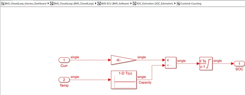
In this coulomb counting method, the entering and leaving currents of the cell are integrated to track the safe chargable time.
here the two input signals current and temperature are taken
the curent signal goes to gain block and the temperature signal goes to current look up table.
then as seen , signals are multiplied and divided as shown and then output is given to discrete time integrator to track the safe chargable time and then SOC is estimated.
advantage of coulomb counting method is its simplicity and low computational cost.
the drawback of coulomb counting method is accumulation of current sensor error and inability to recover from wrong initial condition because of lack of feedback from voltage measurement.
CONCLUSION:
The various objectives given in the question are achieved and the various results are studied.