Week 7 State of charge estimation
EV LIVE BATCH 21
QUES. 1
test condition 1
Cell temerature: Iniatially for 3000 sec the temperature range of cells increases gradually from ambient temperature 288K to 320K.
The temperature of cell (1) is lesser and cell (6) temperature for all stages.
After 3000sec upto 4000sec the cell temperature exponentially upto constant current region and start reduces as current flow reduces in constant coltage and cell balancing region uto 9000sec.
Cell (1) max temp increases raised upto 302K and cell (6) temp raised upto 317K
After 9000 seconds the temperature still reduces and remains stable at reaching ambient temperature.
BM State:
For 3000 sec the battery module in drive mode (dischargiing)
From 3000 sec to 4000 sec the battery module in balancing standby mode
After 4000 sec upto 9000 sec the battery mode in charging and balancing mode
After 9000 sec only post charge balancin mode operates upto end of simulation.
test condition 2
In the second test condition there is only driving and charging phase where for 10000s the vehicle is driving phase and from 10001 to 20000 s the vehicle is in charging phase.
Cell temperature: Here cell (1) having lesser tem variations from 288K to approximately 302.5K
Cell (6) is having higher temp variation 288K to approximately 322.5K
The cell temperature are slightly reducing in between the drive modes as these durations are in stndby modes.
BM State:
Entire sequence is performing in drive mode
Small duration of standby mides are not plotted in this plot a simulation upto 10000aw command is given as drive mode
But in actual practical situation standby modes are not present as battery current drains by other small auxilliaries of EVs
Here, the SOC reduces from 80% to 0%(as current drained for longer duration)
& balancing of cell is not performed as balance state are in 0 for entire drive mode.
test condition 3
This condition is only to study the cell balancing during the simulation. The simulation is successfully run without faults. The current & voltage value decreases when BMS is balancing the cells. The temp also reduces in this phase and the sate of chage increases to a 100% and continues to run at 100% for the remainder of the duration.
Cell Voltages and pack current:
Initially cell (2), voltages rises from 3.9V(approx) to max 4.2V and stabilised to 4.15V
Cell(1) rises from 3.85V to 4.1V and stabilised at 4.08V
The battery pack current rising from 0A to 30A and starts to reduce to 2.3A gradually at end of full charging upto 2000sec
At 2000s the pacl is fully charged to 100%
After full charge current flow cutoffs.
BMS:
The pack SOC gets fully charged 2000s and emains at full charge for rest of the sequence. The actual state of charge us ariund 93% as full charge shown by UKF and EKF techniques.
Here, from 0sec the cell (6) and (2) starts to balance with respect to cell (1) and all cells are try to balancing at end of simulation.
QUES. 2
Coulomb counting is a technique used to track the SOC pf a battery pack. It works by integrating the active flowing current(measured in amps) over time to drive the total sum of energy entering or leaving the battery pack. Thhis produces a capacity that is typically measured in Amp-hr
SOC is a fundamental concept to understand the use of batteries, which is used to describe the remaining capacirt in a battery. As the SOC is an important parameter which reflects the battery performance, accurate estimation of the SOC can not only protect the battery, prevent overdischargege, and improve the battery life but also allow the application to make rational control strategies to save energy, SOC is defined as the ratio of current capacity of a battery to its normal capacity and represents the maximum amount of charge that can be stored. The equation of SOC is
SOC(t) = Q(t)/Q(n)
where, Q(t) - current capacity & Q(n) - nominal capacity
The Coulomb counting method measures the discharging current of a battery and integrates the discharging current over time in order to estimate SOC. Coulomb counting method is done to estimate the SOC which is estimated from the discharging current, and previously estimated SOC values. The equation to calculate the SOC using Coulomb Counting is given as
SOC(t) = SOC(t-1) + [l(t)/Q(n)]*∂t
Where, SOC(t-1) - previous SOC value & l(t) - discharge current
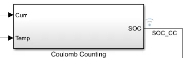
The sub-system that calculated the state of charge in the BMS model is given below
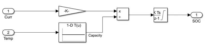
The system uses current and temp as the inputs where the current is passed through a gain block and the temp is passed through a 1D look-up table. The current and temperature are then divided and integrated to obtain the state of charge.