Week - 4
Solution 1.
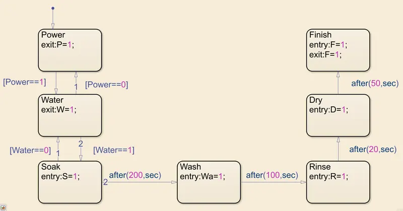
For the washing machine to work according to the asked requirements, following is the LOGIC CHART:
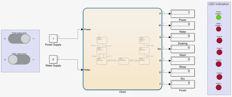
The below images shows the SIMULINK MODEL of the washing machine when only the POWER switch is turned ON, the LED indicates green for the power ON and rest are red indicatring no other operation is working, the second image shows both the POWER & WATER SUPPLY switch ON, and therefore the other operation continues working eventually leading to FINISH, shown by GREEN LED.
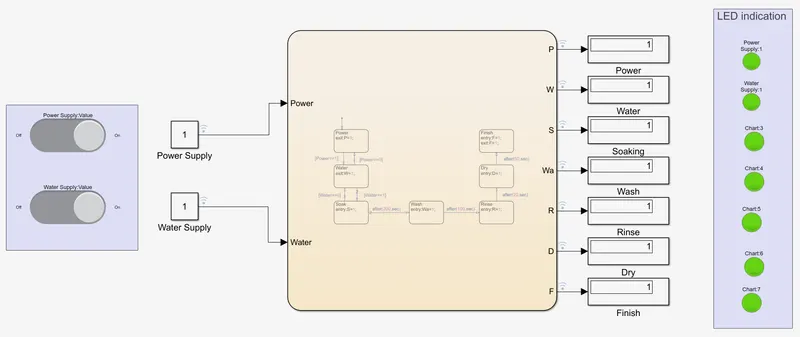
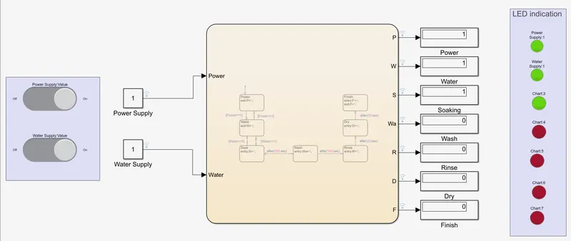
The following images shows the SIMULINK MODEL at different times, continuing the process as
- Soaking time 200s followed by Washing time of 100s.
- Then rinsing happens for next 20s & dryer runs for 50s
- Finally, the last LED( FINISH ) turns GREEN showing the process had ended.
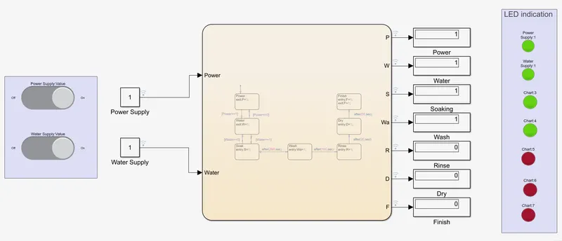
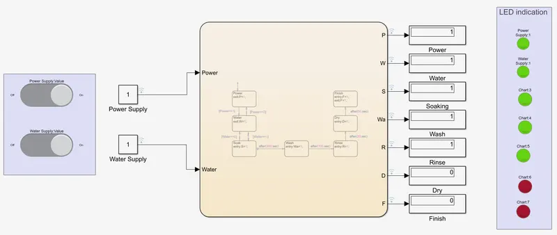
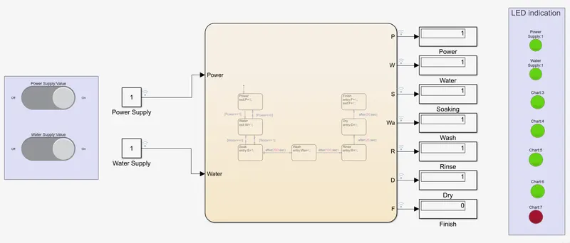
RESULT:
SOLUTION 2:
Below is the SIMULINK MODEL for gear shift
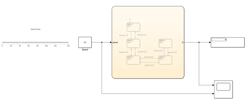
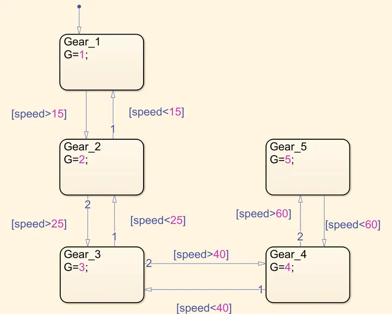
The LOGIC CHART is made according to the following requirements:
Speed Range(kmph) Gear
0 to 15 1
16 to 25 2
26 to 40 3
41 to 60 4
Above 61 5
RESULT:
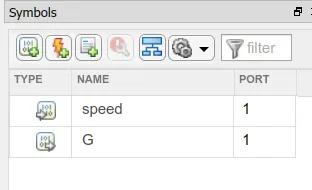
when the slider scale is moved to any speed, the constant block shows the speed and passes it as an input to the chart, and the output is shown by the display block, for example if the speed is 41, the output is 4, that means 4th gear is in place.