Week 7 State of charge estimation
First of all let us undrestand about test harness model at t glance:
- There are two block to give input test cases one is Test Sequenc Variant and another is Manual Variant.
- If we want to provide test input manually then have to choose manual variant otherwise Test Sequenc Variant has three prewritten test cases just select one at a time.
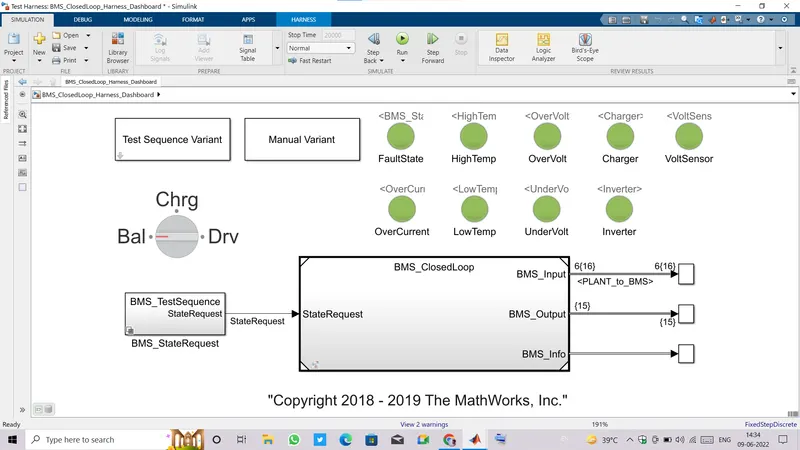
- There is one Rotatary switch which shows the BMS state whether it is in charging state, in driving state or balacing the cell voltages.
- We can see there are nine lamps connected with different different parameters of states of Temperature, Voltage, Current etc these all are of boolean datatype which can either be zero or one. If any value goes beyond or under an specified safe limit.
- Lamp settings are such that if zero value occurs they glow in Green color otherwise glow in Red color, red means there is any problem with that particular parameter.
- Lets's have look at BMS_ClosedLoop block.
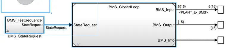
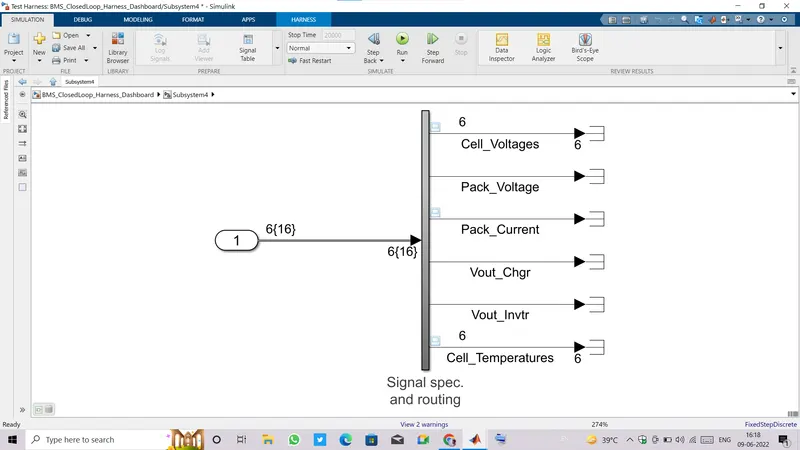
- It is taking input test sequence and three output ports are connected to three subsystems, first output subsystem is having six cell voltages ,Pack voltage, pack current, Charger voltage,inverter voltage and each cell temperature.
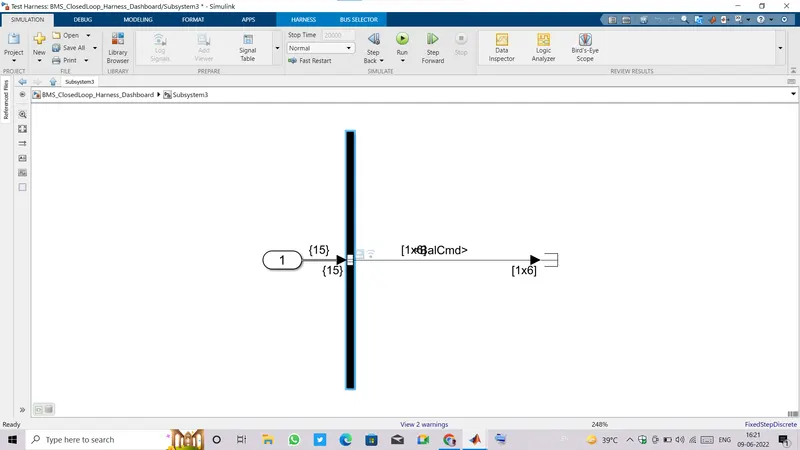
- Second output subsystem is having individual Balance commands for six cells.
- Third output subsystem is having all safety parameters to which lamps are connected.
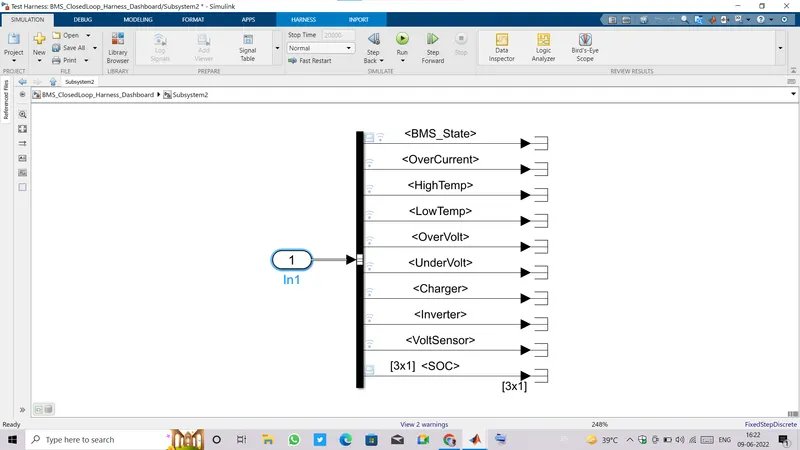
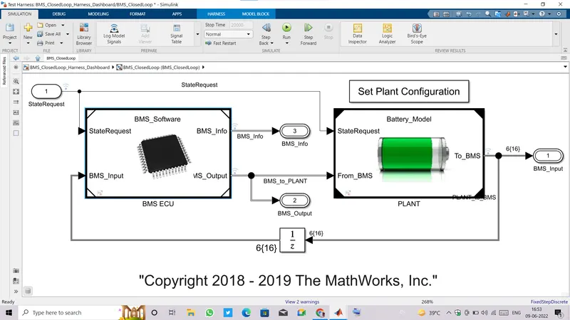
- Inside BMS_CloseLoop subsystem there are BMS ECU subsytem and Plant.
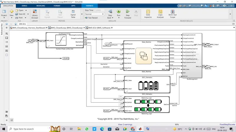
- BMS ECU is further consists of various blocks which are sensing voltages ,currents ,temperatures by using Stateflow logic ,Calculation of SOC by coulomb counting, Kalmans method(Uscented &extended), also giving Balance command to each cell.
- BMS ECU is giving input to the Plant where cells are connected.
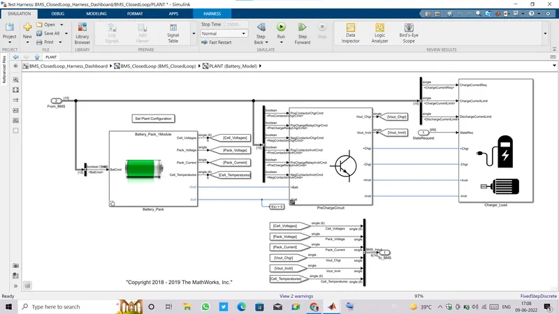
- Plant consists of Battery pack, Precharge circuit, Load and Charger.
- Also there is one feedback circuit by which the voltage, currents and temperature , charger voltage, inverter voltage are sensed and fed back to BMS.
- Let's start the simulation of given test cases.
1). Simulating the 3 test cases from harness dashboard:
- Open BMS_ClosedLoop_Harness_Dashboard model from given file.
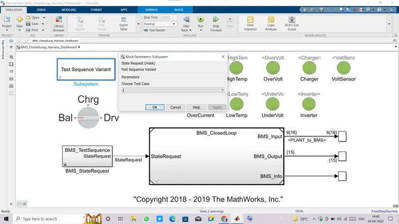
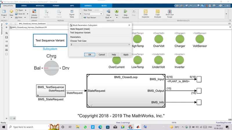
- We can choose three test cases one at a time from a block named Test Sequence Variant.
- Just make double click on that block it'll ask to select test case to be given as input to the model.
- At the very first we are going to select test case 1.
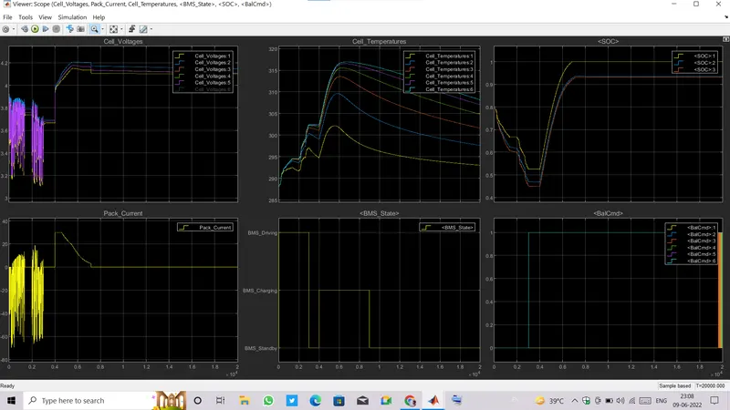
- Observing plots in scope window.
- From BMS_State plot, it can be seen that till 3000 secs battery current is accoding to the Driving mode.Hence, we can see the frequent charging discharging current wave and voltage is also raising in falling accordingly.
- Along with rise in voltages of each cell, temperature is also increasing gradually. Voltage of Cell 1 is lowest amongst all and hence its increase in temperature is also less than remaining cells.
- The SOC calculated from all three methods are decreaing gradually till 3000 secs as current is flowing.
- From 3000 secs BMS_State switched to Standby mode as there is no current flowing and also cell balance command got actived at this moment.
- From 3000 to 4000 secs current was zero so that all voltages are stucked at their latest values.
- As there is no current flowing the cell temperatures are also start decreasing during this time period and also SOC stays on its latest value for this time period only.
- From 4000 secs the BMS_State switched to Charging mode and current value reaches to its peak(30A) and from now constant current charging has started and it continued till nearly 4600 secs, all cell voltages are started builiding to their set values during CC charging as a result SOC is increasing
- As all cell voltages reached to their set value now charging mode changed to Constant voltage, in constant voltage mode charging the current started falling exponentially.
- We can see the Temperature rise is more steep during charging of cells.
- Charging mode is on till 9000 secs hence battery is charging till SOC attained its maximum value or we can say till the battery gets fully charged.
- As battery gets fully charged ,its current becomes zero and temperature started falling down.
- Also the cell balancing mode is on, so that all cells voltages are try reaching the lowest voltage amonst all either by active or passive balancing(here passive balancing is used).
- All cell voltages are trying to balance their voltage near to Cell 1 voltage because cell 1 has the lowest full voltage and it is the only way to balance cell voltages by dropping other cell voltage near to the lowest one.
- At time 7165 secs there is very little voltage drop can be seen in all cell voltages that is because of current becomes zero and hence there is no drop in internal resistances.
- From 9000 secs BMS_State changed to standby mode but cell balancing is happening till the end.
- some cell are balanced ,and some are frequently balancing and unbalancing.
- All plots from scope window is given below in image.
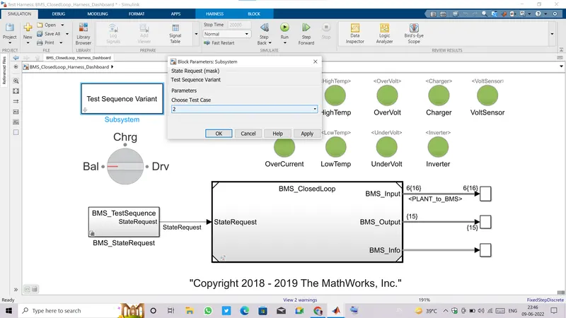
- Now, selecting test case 2.
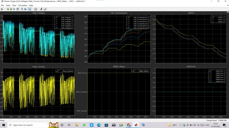
- In this test sequence, BMS_State is in driving mode all the time.
- Balance command is off because in passive balancing mode balancing is possible during charging time only.
- Cell voltages are rising and falling according to the driving current.
- And cell temeperature was also keep on increasing as the battery was frequently charging and discharging.
- SOC was gradually decreasing and it became zero too early at around 8692 secs hence simulation ended at this time earlier than run time.
- Now, checking plots for test case 3:
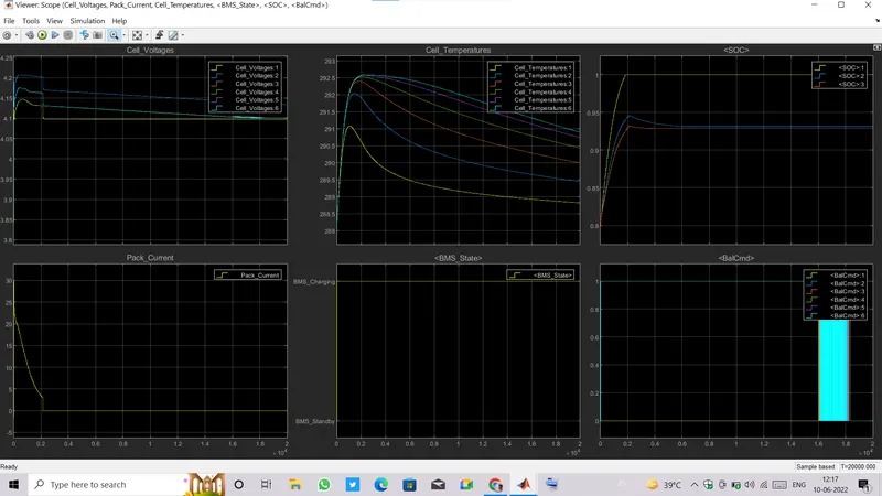
- In this test case,BMS_State at standby mode for very short duration of 1.7 secs so the current was zero till that time and no cell voltages build up.
- After 1.7sec BMS_State switched to charging mode, now current reaches to its max value, 30A.
- Now cell voltages are started building.
- Constant current charging occurs for very short duration because battery SOC was already at 80%, and all cell voltages are near to maximum already.
- All cell temperatures are increasing because cells are charging with high constant currrent value, and keep on increasing till the charging continued.
- Constant current mode ends and then charging started at constant voltage mode andd circuit current started decreasing exponentially till near 2000 secs. When charging is done, BMS disconnected the charging circuit and current reaches to zero causing slight voltage drop atthat moment.
- Along with charging, Cell voltage balancing is also happeninig simultaneously.
- Cell temperatures are now falling down after current flow is stopped.
- All plots are shown in image below.
2). Coulomb Counting:
- Coulomb counting is the counting of charges flowing in electrical circuit over a period of time or in another words coulomb counting is the integration of current flowing in an electrical circuit over a specified time period.
- And when this coulomb counting is taken and integrated over an hour and then divided by Capacity of battery(a constant value), the outcome will be the SOC.
- Let's see how it works.
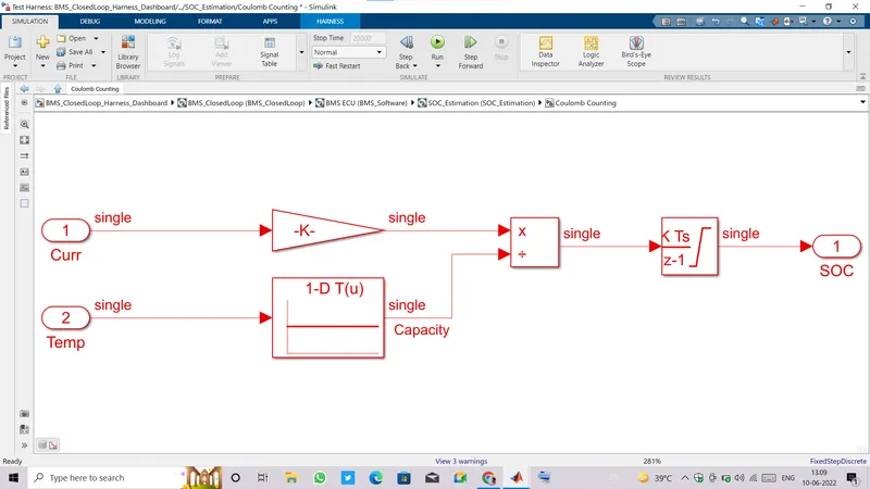
- In an image given above, circuit current is taken and divided by 3600sec to change the unit of time to Hours from sec.
- Second branch has battery capacity (which is a constant value in Ah),which is temperature dependant.
- Current is being integrated over a period of time(in sec) which will give a value in Ampere-sec but using a gain block (with value1/3600) , time changed to hours and now overall outcome will be in Ampere_hour, then this value will be divided by capacity(Ampere-hour) and we got SOC of battery.
- SOC is the ratio of remaining or present capacity to the full capacity(rated), The remaining or present capacity is calculated by coulomb counting and that is how SOC is being calculated in this model.