Project 1 (Mini Project on Vehicle Direction Detection
1. Aim: To develop a model with features like detection of the road side sign right ahead using camera sensor, process it with apropriate algorithm and display it (whether sign is Left, Right or Straight) into vehicle's dashboard so that driver gets recommendation in which direction it is safe to to turn his/her Vehicle.
2. Description:
I.CREATING MODEL:
- Open a new Blank model canvas.
- Load a subsystem into it.
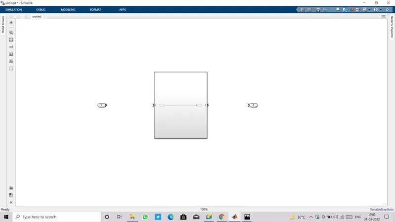
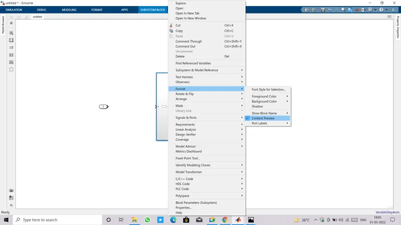
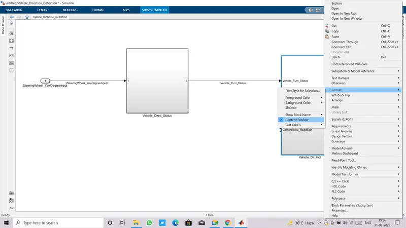
- Making some setting changes like off the Content Preview , On Show Block Names . For all this set-up just double click on subsystem block and Goto Format a drop down will appear click on Content Preview.
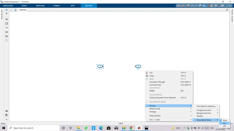
- To On Show Block Names go inside subsystem select blocks and right click ,again do the similar drill as we just did.
- Now making the algorithm for inputs and outputs.
- Load all the required blocks.
- As we need to compare a input coming from Steering wheel(SteeringWheel_YawDegreeInput) with three given calibration values(Right_Turn_AngularLimit, Left_Turn_AngularLimit, Straight_Drive_Steering_Angle), It require one input block, three Constant blocks for calibration values ,two Relational Operators for Comparison of input from steering wheel with all three calibration values.
- And at the end we only get a single output Vehicle_Turn_Status(as vehicle can make turns only in either of these direction one at a time) if any of these comparison is satisfying which is only can be achieved by using switch blocks , we need two switch block.
- Also naming of all input and output blocks with their appropriate names is our field of concern, so do it simultaneously.
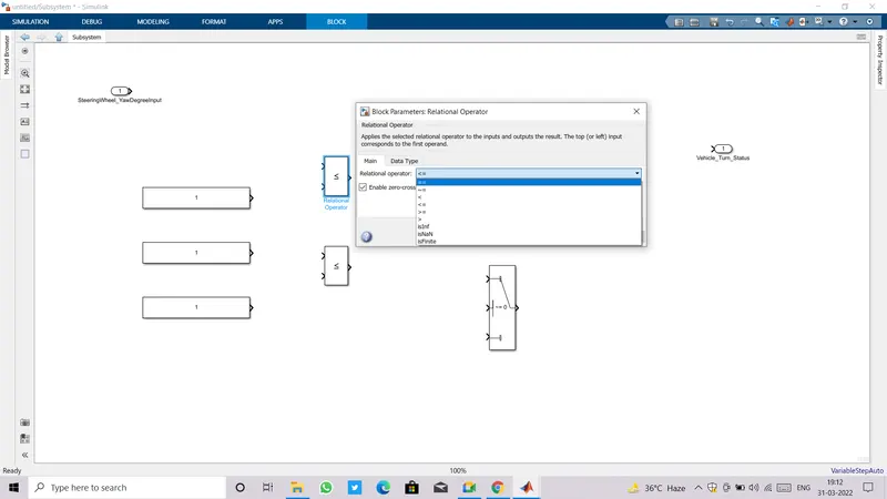
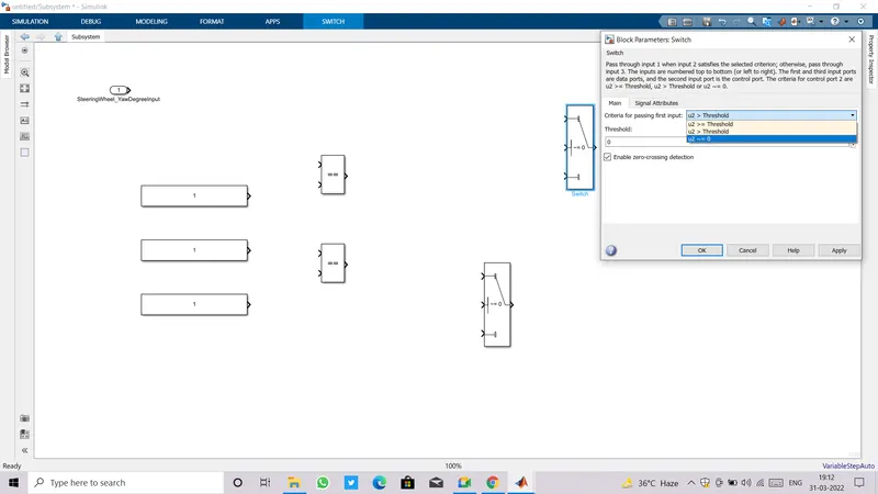
- Freshly loaded blocks are set to their default parameter values so we have to make changes explicitly as per our requirements.
- For example ,in above image we can see that relational operator is by default set to '<=' but here we need to check equality so change it to '=='.
- To change any parameter value just double click on that particular block, a pop up window will appear where you can make required changes and after that must click on Apply.
- Do set-up for both relational operator blocks.
- Similarily, make set-up for both the switch blocks.
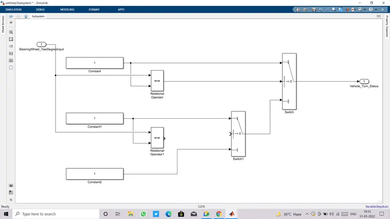
- Make all the connections using signals accordingly.
- Now provide calibration value to each constant block, instead of assigning Numerical values give their names like k_Right_Turn_AngularLimit, k_Left_Turn_AngularLimit, k_Straight_Drive_Steering_Angle.
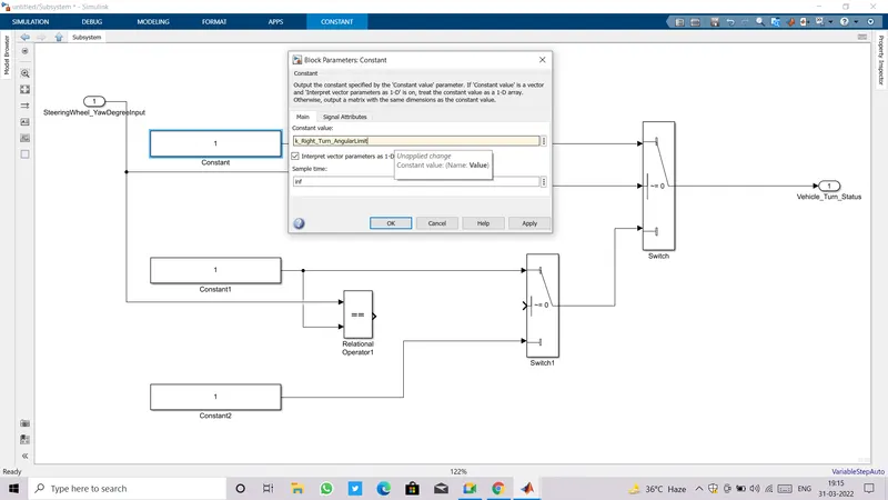
- Provide all the three calibration values.
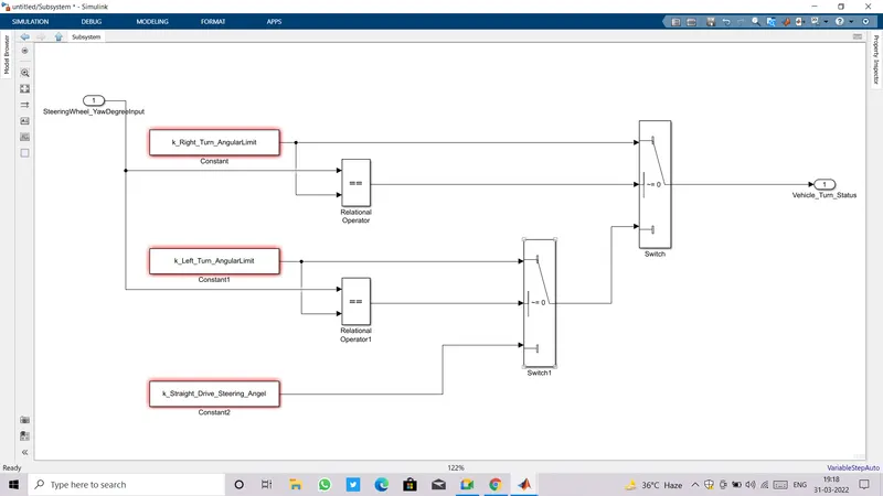
- Initial level of algorithm has been completed, now come outside the subsystem.
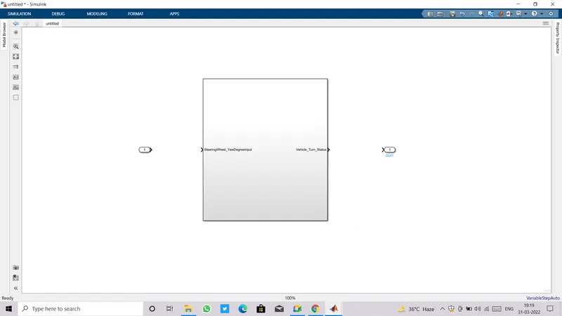
- Connect input port of subsystem with input block and name it as SteeringWheel_YawDegreeInput and name outermost subsystem as Vehicle Direction Determination.
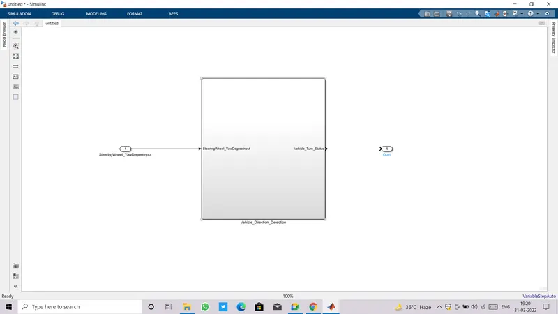 and
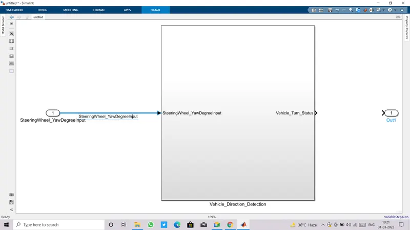
and - Do labelling of signal going from input block to input port.
- For labelling of any signal double click on signal line.
- The signal label name must match with name of block from which signal is coming out.
- Again go inside subsystem, tap hold and drag cursor ,make selection of blocks accept input and output then release hold.
- Three dots will appear on the top as shown in image below.
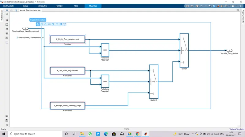
- Choose Create Subsystem and make second level subsystem.
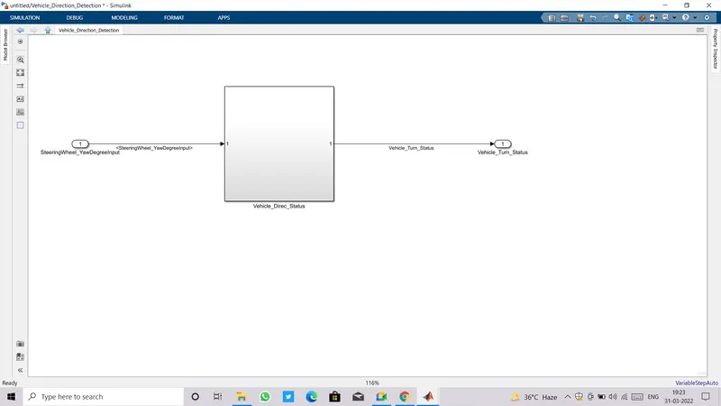
- Name this subsystem as Vehicle_Direc_Status.
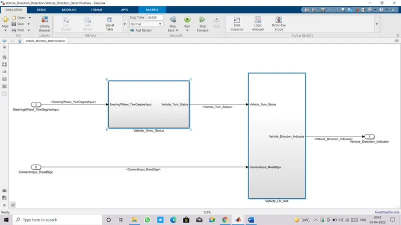
- Now go for the second requirement.
- Create a new subsystem Vehicle_Direc_Indi on the same canvas where Vehicle_Direc_Status exists.
- First input to this subsystem is the output coming from subsystem Vehicle_Direc_Status and the second input is coming from Camera sensor as CameraInput_RoadSign.
- The output of this subsystem is Vehicle_Direction_Indication.
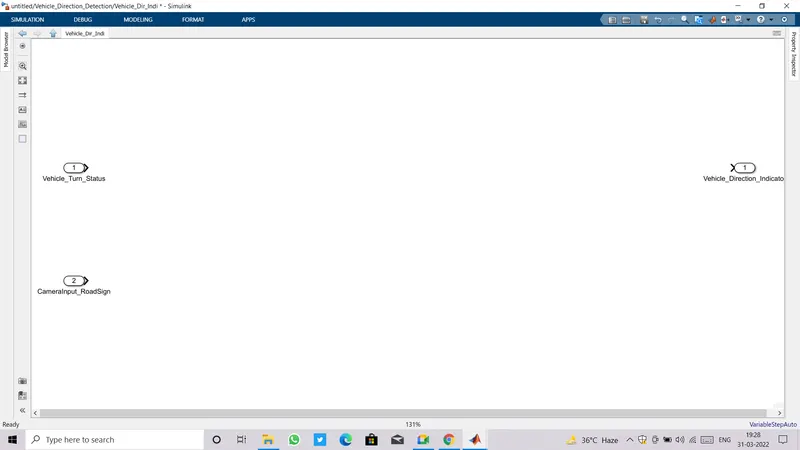
- Now, turn to apply algorithm for this stage.
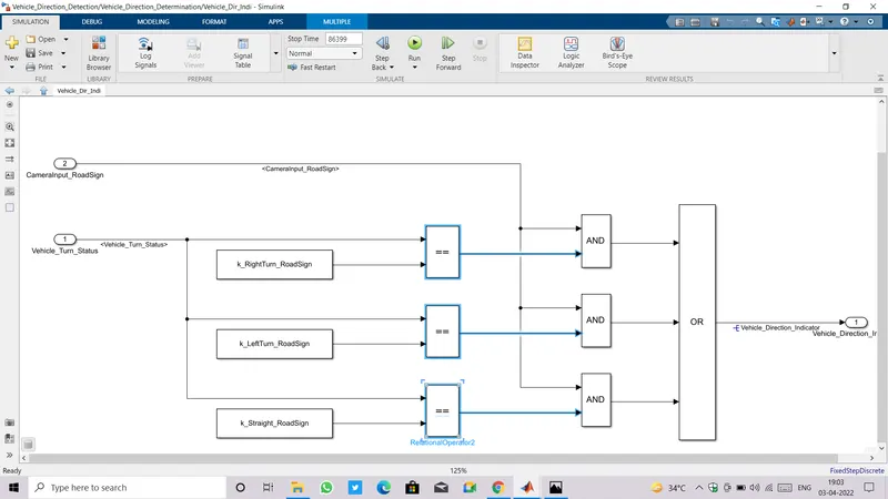
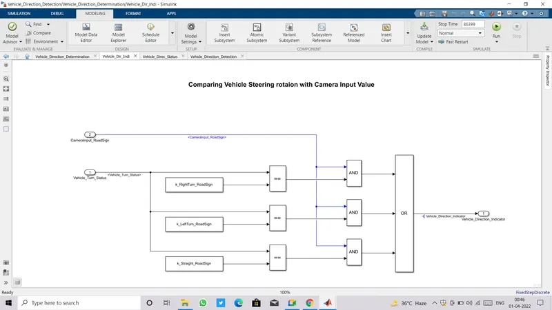
- Input (Vehicle_Turn_Status) needs to be compared with three calibrated values RightTurn_RoadSign, LeftTurn_RoadSign, Straight_RoadSign by three using realtional operators as shown in image below.
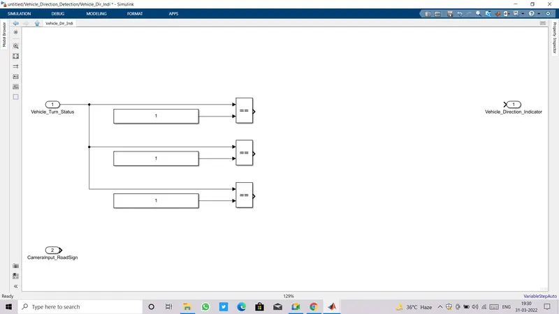
- Calibration values are always given by using a constant block and instead of assigning numerical values give names of calibration values.
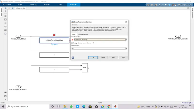
- After ,Vehicle_Turn_Status being compared against each calibration values,the respective outputs from each relational blocks are fed to one port of three different AND logical block.
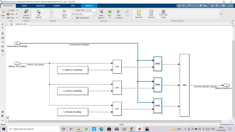
- Other input port of each logical AND block is fed by CameraInput_RoadSign.
- Actually the whole process is: Signal Vehicle_Turn_Status is compared against calibration values (Calibration Values: RightTurn_RoadSign, LeftTurn_RoadSign, Straight_RoadSign), if each of them is found equal, then each of the three corresponding output is compared against the camera input signal by using Logical operator.
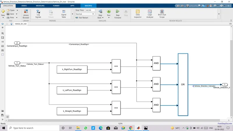
- And the final output is one amongst three signals coming from Logical AND operator.
- Here how we select one out of three, we are using a logical block again but this is Logical OR operator.
- The final output is a signal Vehicle_Direction_Indicator.
- Get out of this Subsystem, and turn Off content preview.
- At this level we need to connect a input port and output blocks highlighted in imange shown below.
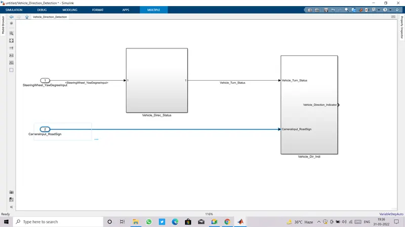
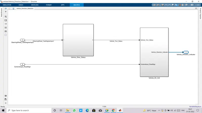
- Getting out of this subsystem take us to the top level of model.
- Here also to need to connect input and output block highlighted in image shown below.
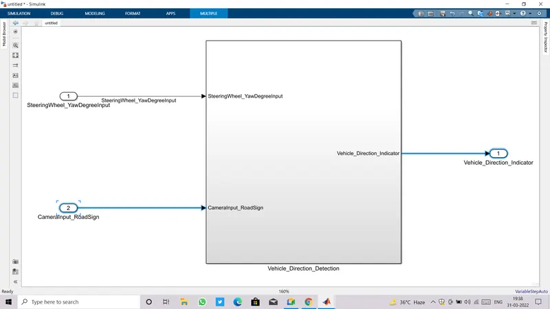
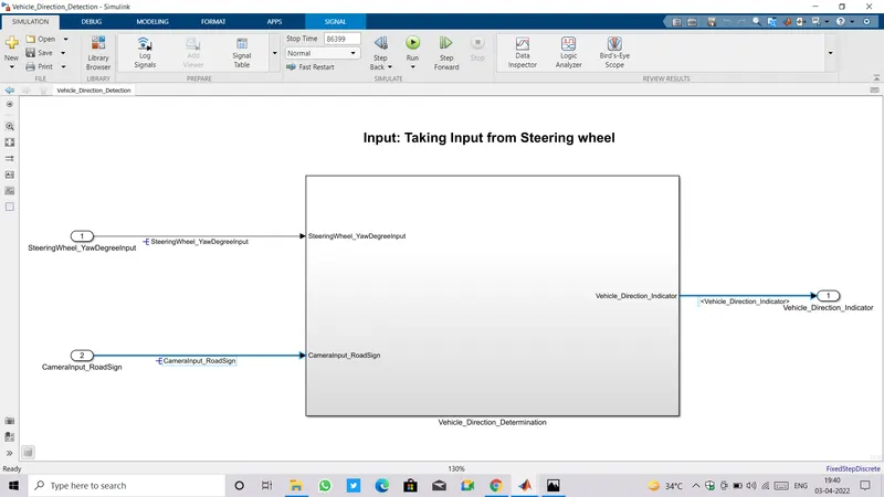
- Along with adding blocks, we need to add signal labels or signal propogation as shown in image below.
- At the top level, Signal Labelling can be done but if the same signal is propagating throughout the different levels of subsystem it is preferred to use Signal Propagation.
- Steps for Signal Propagation: Right click on signal>>pop window appear, choose Properties>>Tick on Signal Propagation checkbox.
II. CREATING DATA DICTIONARY:
- Now it's time to create Data Dictionary to access all the input, output signal values and also the Calibration values.
- Steps to create Data Dictionary: Goto Model Properties >> External Data.
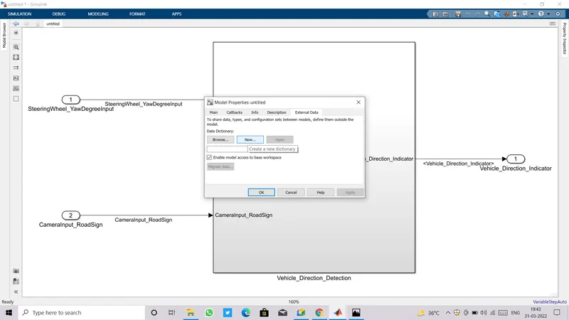
- Select New, it'll ask for name.
- Name your Data Dictionary and uncheck the box present at the bottom which reads ''Enable model access to base workspace''.
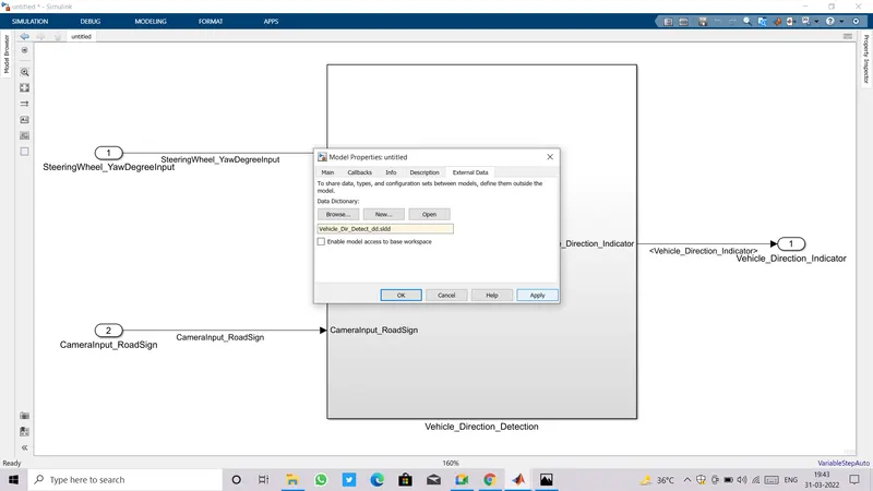
- If Data Dictionary is Created succesfully, it'll start showing to Explore Data Dictionary at the bottom Left corner of the model window.
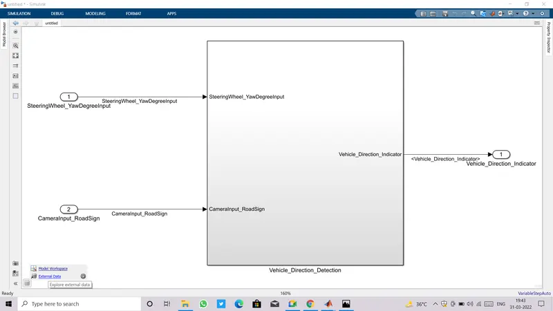
- Click on External Data showing at bottom left corner of model window, a new window of model porerties will going to open.
- Click on drop down arrow of Data Dictionary, Design Data appear.
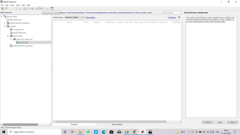
- We are ready to add all parameters of input ,output and calibration. Parameters like Initial value, Min and Max value, Dimension, DataType, Storage class, Unit can be set created a data dictionary.
- Add all the Signals and Calibration values which are given to us.
- Use Simulink Signal from the top icon tray to add input and output signals.
- Use Simulink Parameters from the top icon tray to add Calibration values.
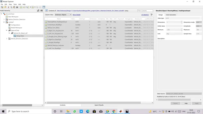
- The storage class for Input signals should be ImpotedExtern , for output signals: ExportToFile and for Calibration values: ConstVolatile.
- If choosing ExportToFile or ConstVolatile as storage class, we must have to provide HeaderFile and DefinitionFile as shown below.
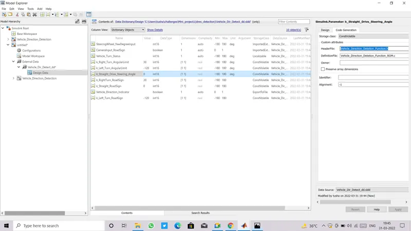
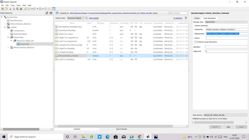
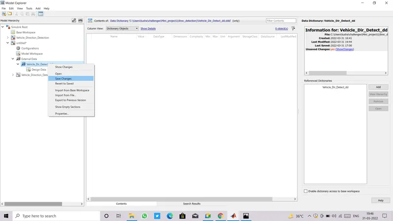
- After addiing all values, go to list of files present at the left side ,find Data Dictionary, make right click on it, a context menu appear , select Save Changes.
III.REQUIREMENT TAGGING:
- First of all create a requirement file, flie maybe word ,excel,MATLAB or in some other format.
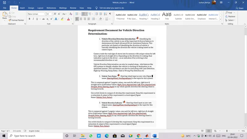
- Minimize Requirement file window size and select the text to link with model.
- It requires that model and requirement file must be open side by side, do not even minimize any of them.
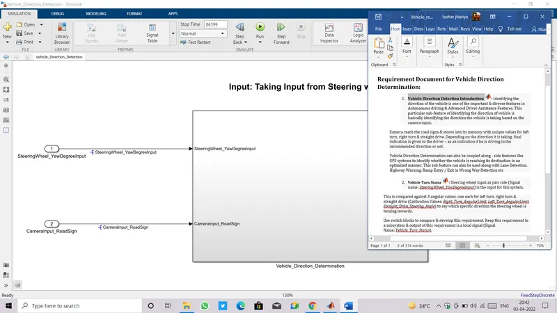
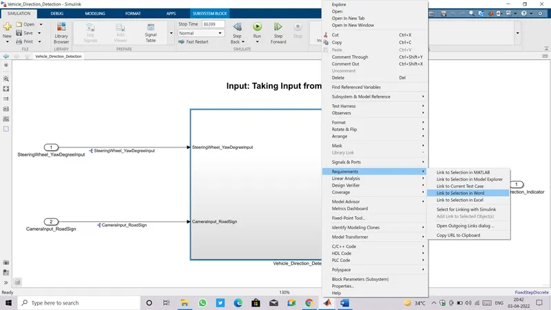
- Now open model window and make right click on top level subsystem.
- It'll show a context menu, Select Requirements>>Link to selection in word.
- After linking file succesfully again right click on subsystem select Requirements, verify are selected texts available in context at the top.
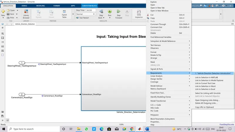
- Click on that linked text will lead to open the requirement file and at the same time will highlight the block with Yellow color to which the file is linked with.
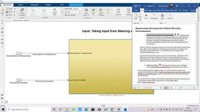
- Do the same drill for each level of subsystem present in the model.
IV .RESOLVING SIGNAL:
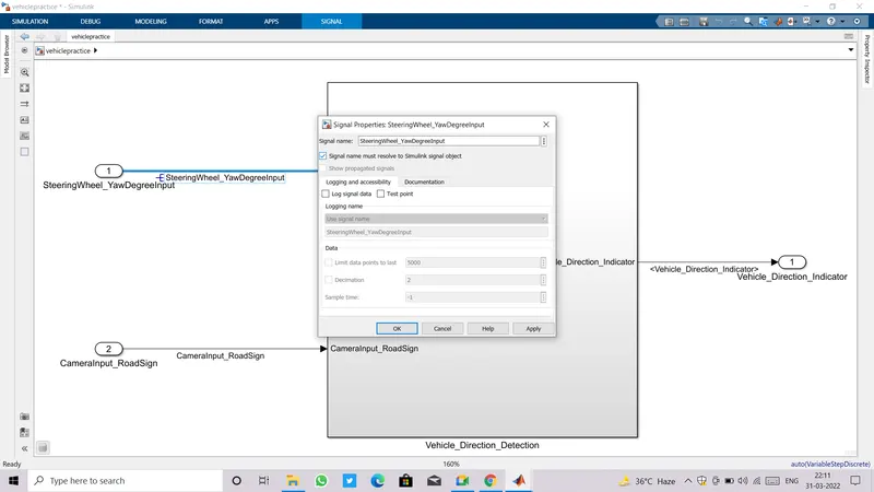
- Signal resolving is done at the top layer of incoming input signal and at the Final layers of output signals.
- Steps fro resolving signal: Right click on signal line>>pop-up window appear>> click on Properties at bottommost>>Signal Properties window appear>>Tick the checkbox that reads "Simulink signal must reslove to simulink signal object".att
- As we click on Apply, we find an "E" with middle line extended backward like symbol appear at starting of Signal label_name.
V . SETTING CONFIGURATION PARAMETERS:
- How to open Configuration Parameters: Goto model window>>Modelling>>Model Setting.
- Another shortcut way to open it, by pressing Ctrl+E.

- First of all change Solver setting ,by default it is set to Automatic we need to change it to Discrete(No continuous states).
- Also change Solver Type to Fixed-step from Continuous step.
- Provide Fundamental sample time as '0.01'
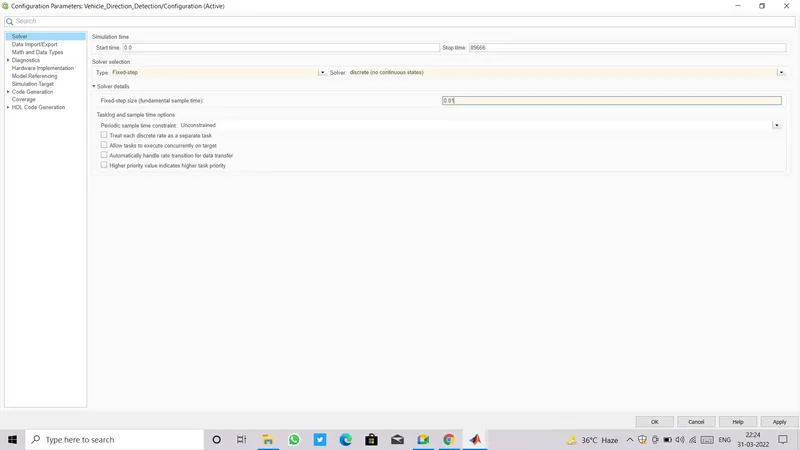
- Making Some changes in Configuration Parameters in accordance with the MAAB Guidlines.
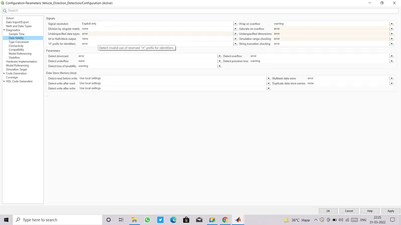
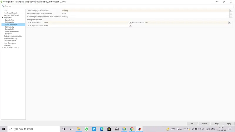
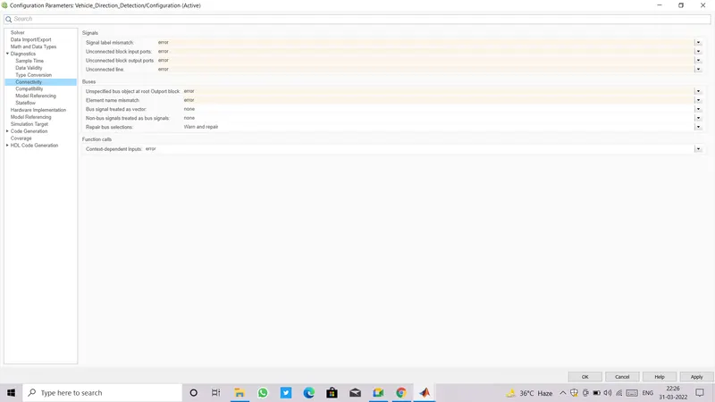
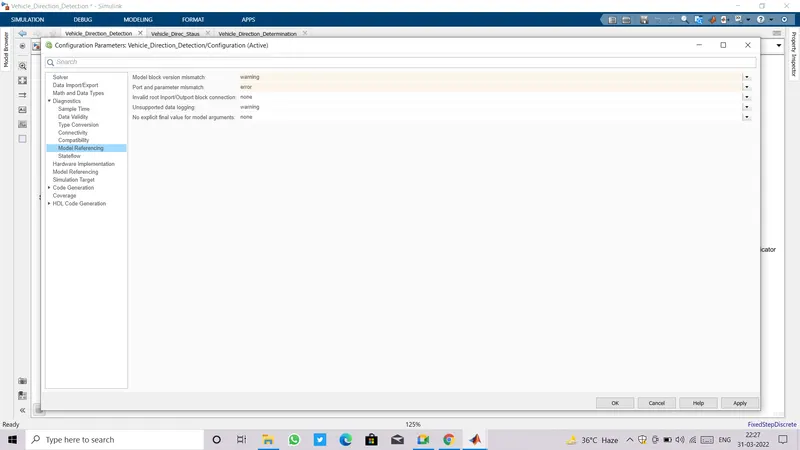
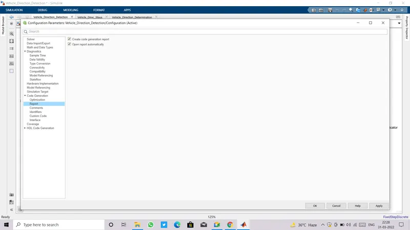
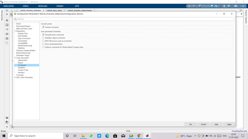
- Most Important change required for Code eneration.
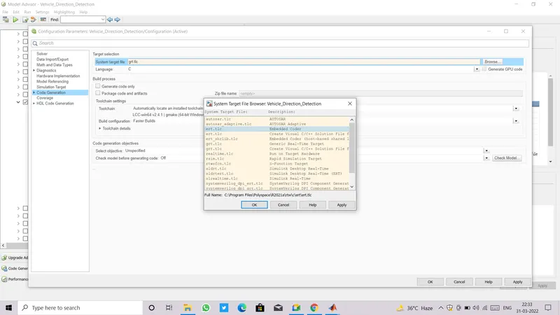
- Goto Code Generation in Configuration Parameter.
- Change the System Target File from 'grt.tlc' to 'ert.tlc' Embedded Coder.
VI . MODEL ADVISOR REPORT:
- Now before going to Generate Code, Run Model Advisor and see its report what errors or warnings are encountering at this stage pertaining to modelling guidelines and standards.
- Try to diagnos those errors/ warnings.
- All the errors must be removed but some warnings maybe retained if not affecting any of the functionality.
- How to open Model Advisor: Goto Simulink Model window>> click on model advisor at the top left corner of window(a symbol of green right tick inscribed in a green circle).
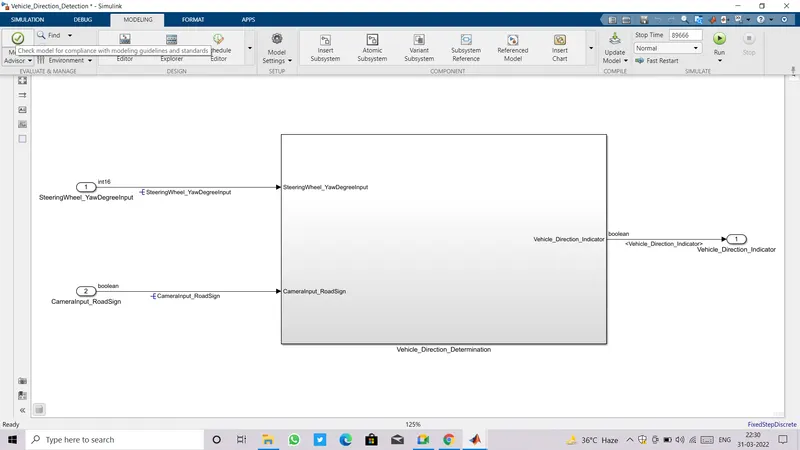
- After clicking on Model Advisor a pop-up window of System Selector appear as shown in image below.
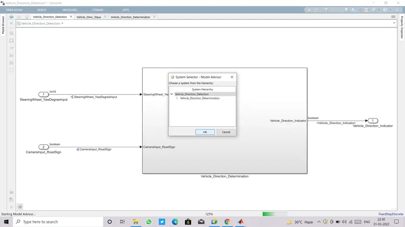
- Select System and click OK.
- A new window will open which consists of two major checkbox: By Product and By Task.
- Go with By Task, inside it there are too many checks pertaining to Modelling standard ,Guidelines.
- We need to tick on the checks for Modelling Standard for MISRA C:2012 , Modelling Standard for ISO 26262, Modelling Standard for MAAB, Modelling Standard for JMAAB.
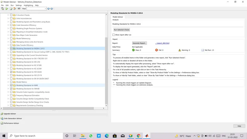
- After marking on all the required checks,click on Run Selected Checks.
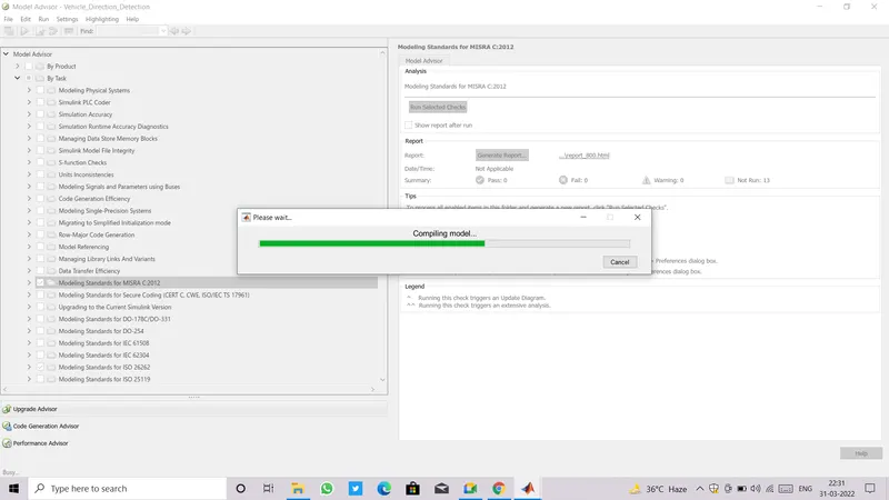
- This Process will take some time to complete.
- Model advisor window has two partitions, left side partition contain all the standard guidelines and right side partition is used for showing the result after running the selected checks whther checks are Pass, Fail, Warning or Not Run.
- Warnings are shown by a caution symbol and passed checks are shown by a right tick symbol inscribed in a green circle.
- If warnings are encountered, each and every warnings are shown on right partition and at the end we are asked to Modify all , clicking on it will modify all the required changes.
- Another way to remove warnings is to manually go through each warning by clicking on given links.
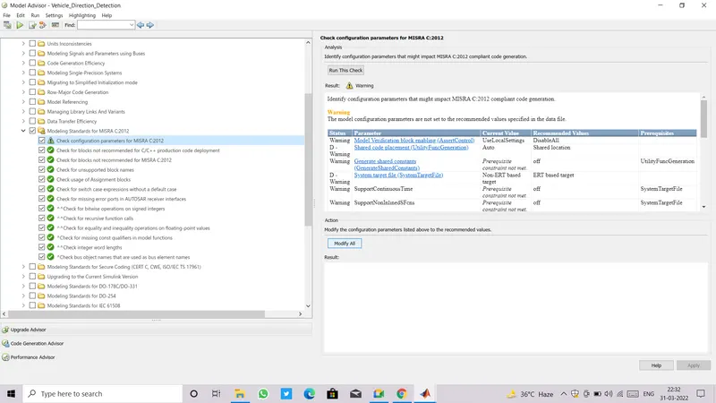
- Once all warning are taken into consideration and modified, we'll again do Run Selected Checks.
- Do modify until get no more warnings.
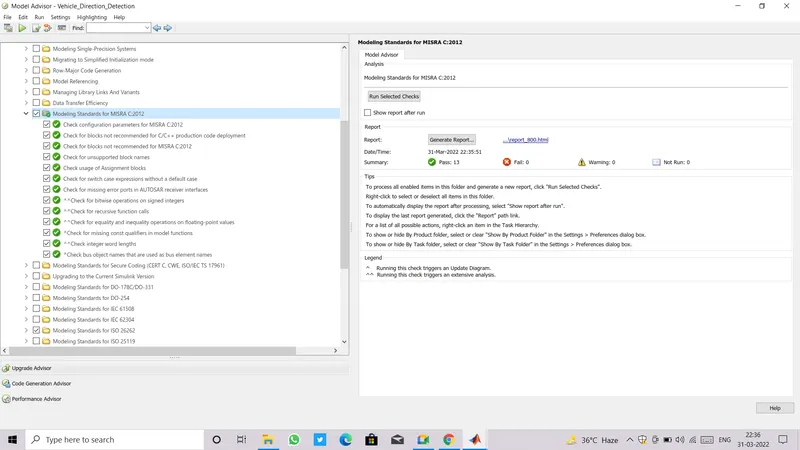
- Here are some examples of how to diagnos and fix the warnings.
- Running the check for Modelling Standard for ISO 26262.
- Got several warnings in Configuration>> Check safety related daignostics setting for data store memory.
- In Right side partition of model advisor window, warning is saying that The model configuration parameters are not set to the recommended value specified in data file.
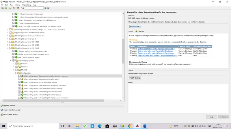
- Click on links of each Warning one by one, it'll direct us to Configuration Parameters.
- Change to recommended setting and apply.
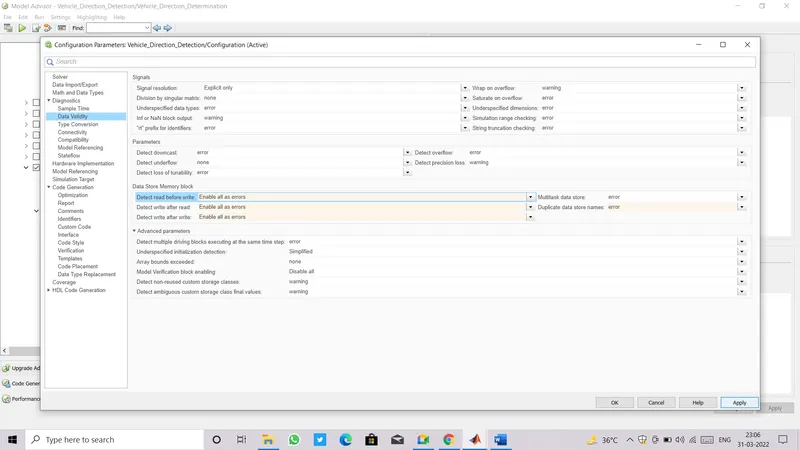
- After Modifying all, again Run Selected Checks.
- Now, tick on the checkbox for 'Show report after run', we can find it just below the Run selected checks.
- After running all the checks we have selected, it,ll show total number of checks we ran,and how many of them are Pass, Fail, Warning and Not Run.
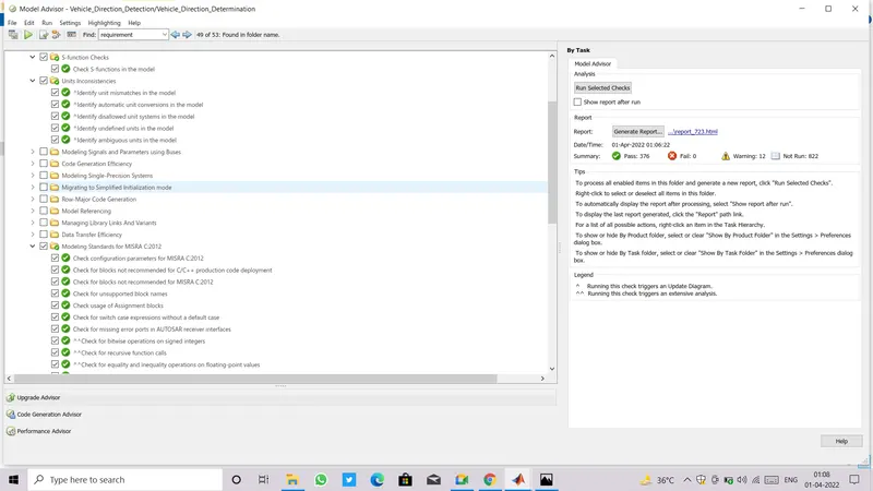
Report:
- We have 1020 checks in total ,and have selected 388 Checks only.
- Out of 388 selected checks we got 376 checks Pass, and 12 Warnings.
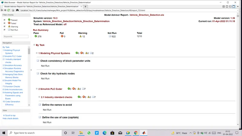
- Those 12 Warnings are irremovable and Can be retained without affecting the functionality of system.
- We need to justify about why those warnings are not removable and not affecting the functionality.
- In an image given below showing Warning which states "Check signal line connections ", "Check signal intersections".
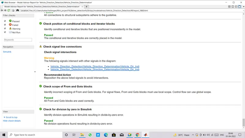
- Click on the given link it'll direct us to the block or signals we got warning for.
- Signals are highlighted in Blue, and
- As we can see in image below that there is no other way to connect those signals to dignose this warning.
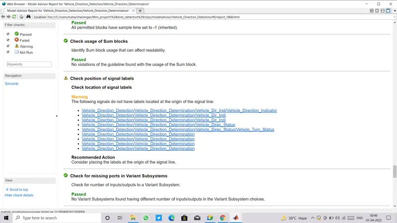
- There is an another warning which states to "Check Position of signal label" ,"Check location of signal label".
- We have placed all the labels correctly,but it is showing warning because some of singals which are originated from inner level subsystem and they can not be put at the starting or top level ,so this warning can be ignored.
- The next warning states to "Check usage of Relational operator blocks".
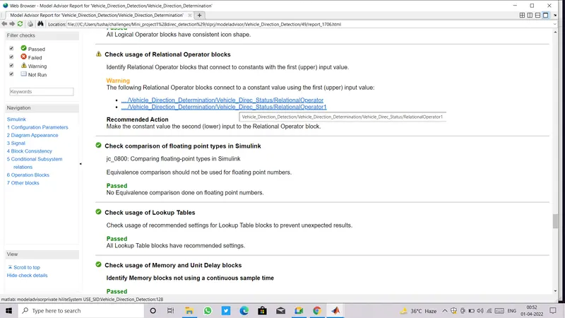
- As per the modelling Standard the recommendation is given to interchange the place of Relational opeartor and Constant block.
- Click on the given link it'll direct us to the block or signals we got warning for.
- Block is highlighted in Blue.
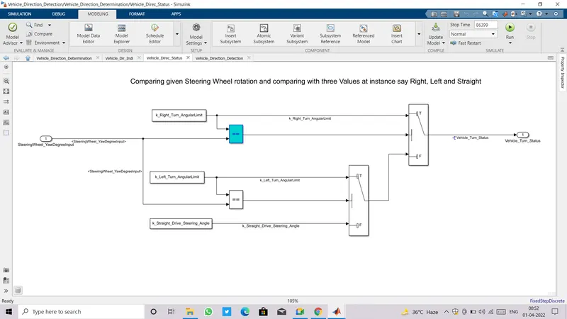
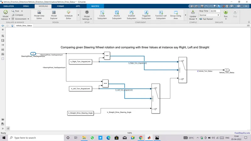
- If we want to remove this warning by interchanging relational and constant blocks, then we'll get rid of this particular warning but it'll start throwing an another warning to "Check signal line connections ", "Check signal intersections" because if we go according to recommendation the scenario is something as given in image below.
- We can clearly see that without any intersection of signals it is not possible to connect them in any manner to avoid warning.
VII. CODE GENERATION:
- We are all set for Code Generation.
- Goto model window and press Ctrl+B.
- Once code is generated,two pop up window appears, one is for Code Generation Report and other is for Code itself.
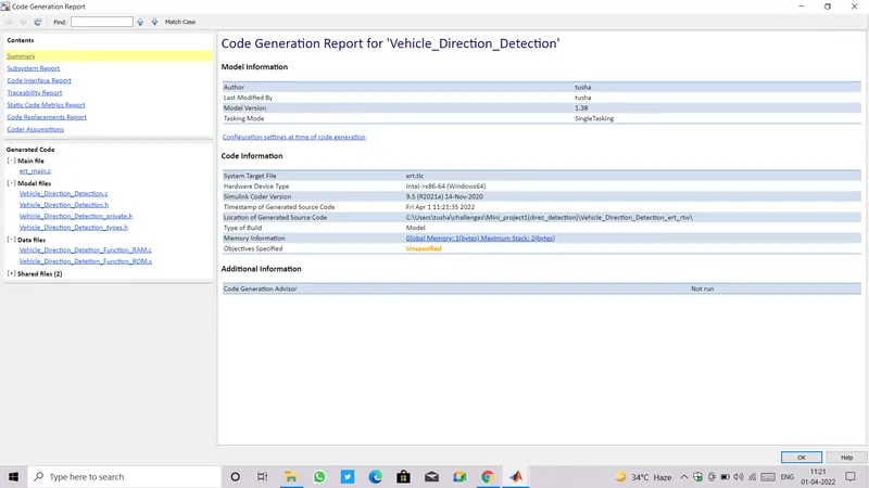
- Code Generation report consists of many files like Main File, Model File, Data file etc , it also consists Summary, Subsystem Report, Code Interface Report, Traceability report.
- Main file cotains all the Main functions of C code.
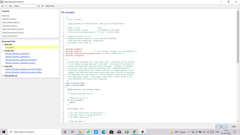
- .h File contains header files.
- .c File contains source code for model.
- To check the code for each level just goto C Code in model window, click on View Code.
- A window for code will open, at the top of that window ,we can find a dropdown sign, clicking on it give us access for each files as shown below.
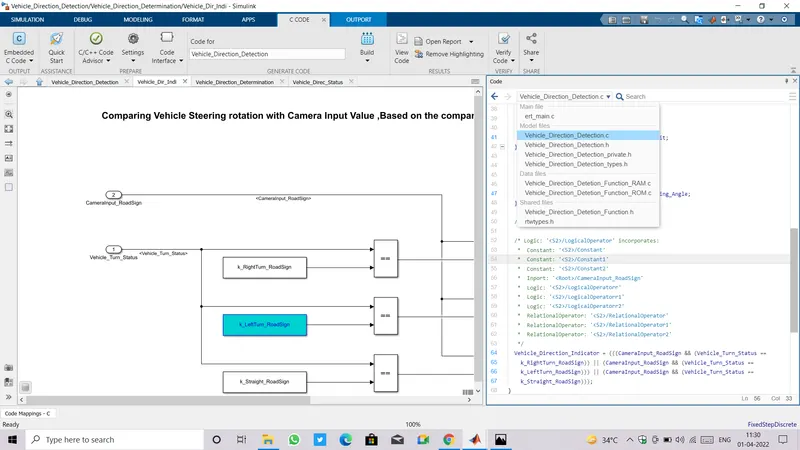
- To verify our generated code we can further go with Verify Code option which is available in C Code itself.
- Simulink facilitate three levels to verify the code,first is Run in Real Time in which code is flashed into an ECU then connected to a hardware, second is Dynamic Code Verification which can be done by SIL/PIL Manager and the last is Static Code Verification it uses Polyspace Code Verifier.
3.RESULT:
- Replace Input blocks for SteeringWheel_YawDegreeInput and CameraInput_RoadSign with two Signal Builders.
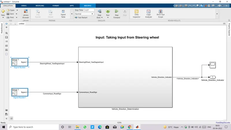
- Setting the Signal Builder for SteeringWheel_YawDegreeInput:
Time Steering Input 0 to 0.01 0 0.01 to 0.02 30 0.02 to 0.03 -120 0.03 to 0.04 0 0.04 to 0.05 30 0.05 to 0.06 -120 0.06 to 0.07 0 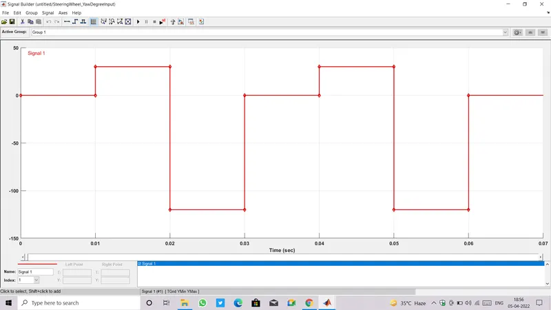
- Setting the Signal Builder for CameraInput_RoadSign.
- Camera input '0' means camera is in Off state and '1' means camera is On state.
Time Camera Input 0 to 0.01 0 0.01 to 0.02 0 0.02 to 0.03 0 0.03 to 0.04 1 0.04 to 0.05 1 0.05 to 0.06 1 0.06 to 0.07 0 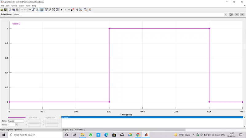
- Scope is connected with the output port to observe the output signals.
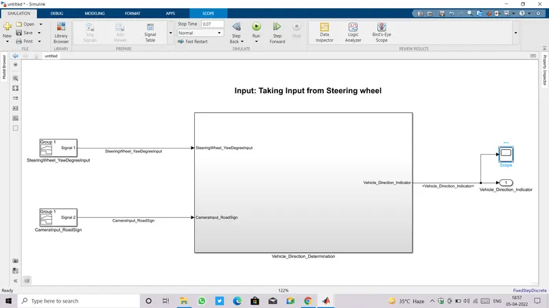
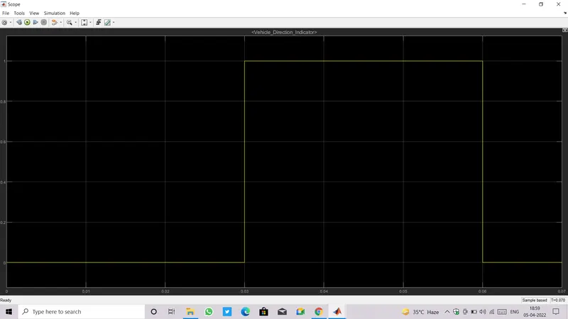
- Output is '0' from Time 0 to 0.03 beacuse Camera input is '0' during this time.
- Camera input is '1' from Time 0.03 to 0.06 that's why we are getting Output.
- Let us consider time duration from 0.04 to 0.05, where Steering input is '30' and Camera input is '1', so we are going to get output.
- The Steering input '30' is first compared with Calibration values Right_Turn_AngularLimit=30, Left_Turn_AngularLimit=-120, Straight_Drive_Steering_Angle=0, as it matched with Right_Turn_AngularLimit ,the output Vehicle_Turn_Status become equal to '30'.
- This Vehicle_Turn_Status is then compared with other three calibration values RightTurn_RoadSign=30, LeftTurn_RoadSign=-120, Straight_RoadSign=0, as it matched with RightTurn_RoadSign, the output from this relational operator became '1' and output from other two relational operator is '0'.
- All the respective output from relational operators (1 , 0 , 0) gone to three logical AND operator as one input and other three input is directly taken from CameraInput_RoadSign(has value '1' for this instance).
- First Logical AND operator provided '1' as output because both input was '1' for it, the other two Logical AND operator thrown '0' output because one input was '0' for them.
- Logic Table for AND operator:
A B OUTPUT 0 0 0 0 1 0 1 0 0 1 1 1 - Output of all three Logical AND is then gone to logical OR operator as 1 , 0 , 0 .
- The overall output(Vehicle_Direction_Indicator) taken out was '1', see OR Logic Table for better understanding.
- Logic Table for OR operator:
A B OUTPUT 0 0 0 0 1 1 1 0 1 1 1 1
- Final output Signal in scope:
- Simulink Model has been developed as per requirement and provided with all necessary files.