Week 7 State of charge estimation
Objective:
- To understand the model developed for Lithium ion battery management algorithm.
- To simulate the model for a specified test harness and write a report on the results.
- To understand coulomb counting and how to find SOC using coulomb counting.
Model:
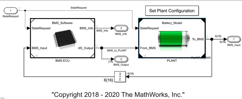
- Plant subsytem contains the battery model along with its protection cicuit.
- The controller is BMS ECU unit,It will sense the parameter in plant and make decision.
Plant System:
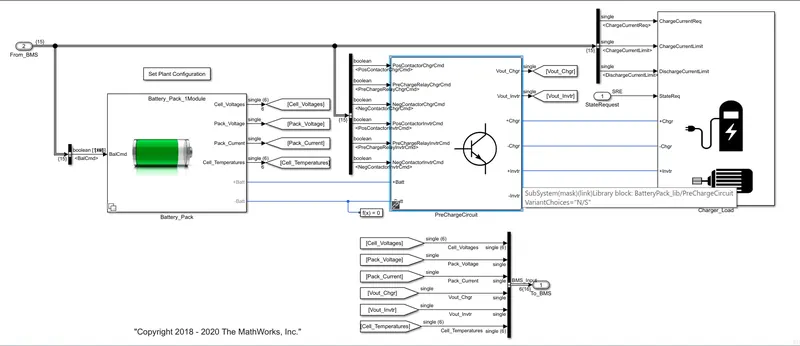
- It contains the battery pack, precharger Circuit and the charger and load circuits.
The Battery pack:
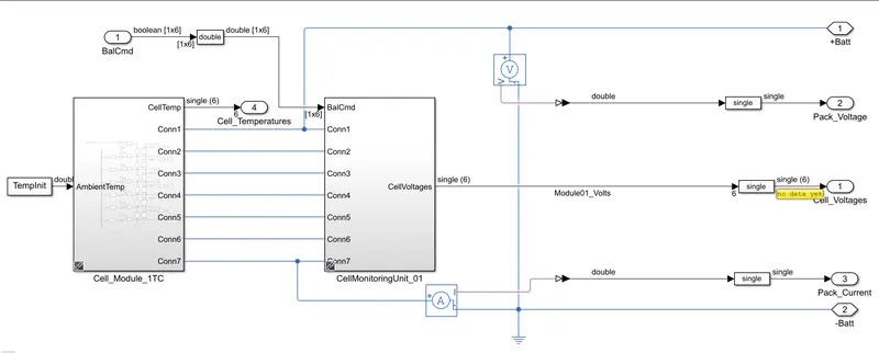
- It contains a battery pack of 6 lithium ion cells in series as one subsystem and a pack of 6 cells is called as modules.
- 16 modules are connected in series to form a battery pack of 96 cells connected in series.
- Cell Module subsystem contains the cells ate connected in series also it maintain temp 25deg for the environment effect,it also measures individual cell voltage and temperature.It alo have assertion block it will stops the simulation when SOC is below 0.001.
- Cell Monitoring Subsystem contains a switch-diode-Resistor pair in parallel for all cells for passive balancing of the cell.
- Charger and Load Subsystem contains the charger circuit and the load circuit.These circuit are implemented with the help of current source.
Pre-charger circuit:
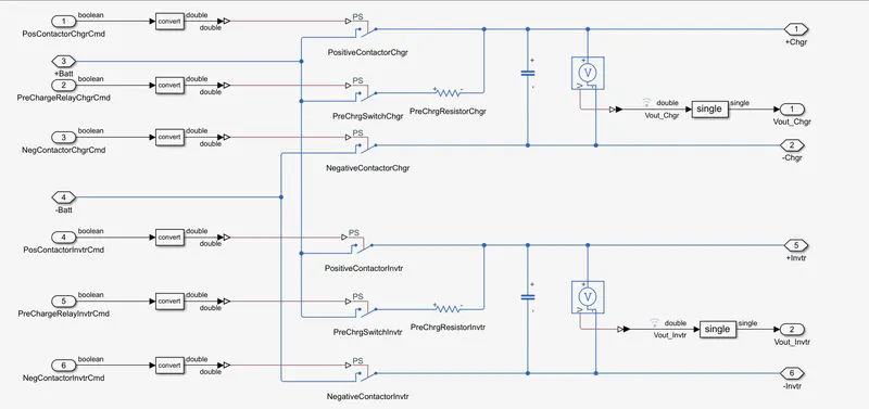
- The pre-charger circuit is essential because when a load or charger circuit is connected to the terminal of the battery will cause a huge pulse of current for very short duration due to the difference in the voltages and resistances and this pulse of short duration will affect the battery capacity, performance and life.
- The pre-charger circuit has number of contactors along with capacitor to avoid the sudden change of voltages.
BMS Control:
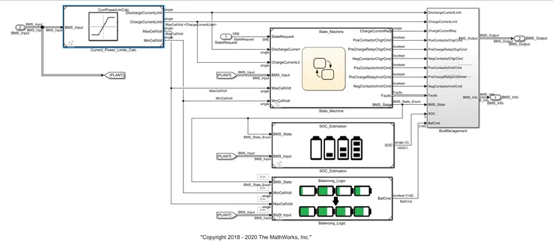
- StateMachine subsystem is model state of battery ie charging,discharging,opening and close of pre-charger circuit
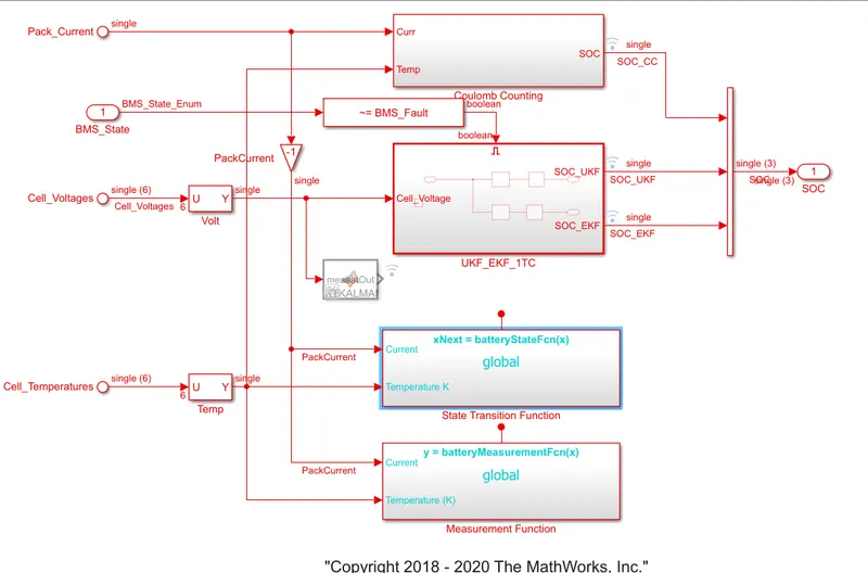
- SOC estimation subsystem is to find the state of charge of battery.The SOC is estimated using COULOUMB COUNTING and KALMAN FILTER methods among this later is more accurate.
- Balancing Logic subsystem is used to perform passive balancing among the cells connected in series.
Test Case1:
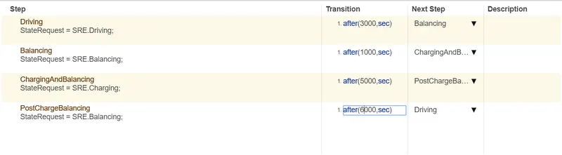
- In this test case intially in driving state after 3000s it goes to charging state firstin cc charging and cv charging mode and pre chraging cell balancing is done.After 1000s it goesto stndby mode ie noload/open circuit condition and then it goes to driving mode.
Case1 Result:
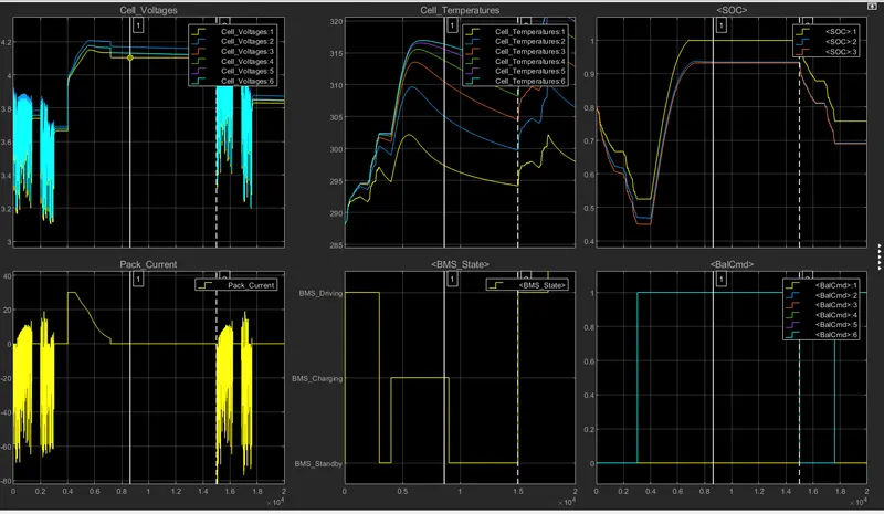
- Under this testcase the fault conditions are not tested,the Temp plot shows thus the cell6 has high temp compare to cell1 because the cell1 is close to outside environment hence cooling is faster.
Test Case2:
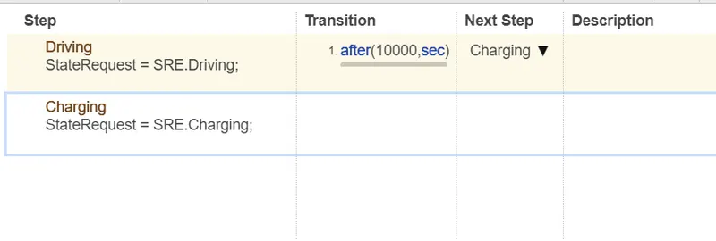
- In this test case the simultion start with driving state with 80% SOC after 10000s it made a transition from driving state to charging state.
Result:
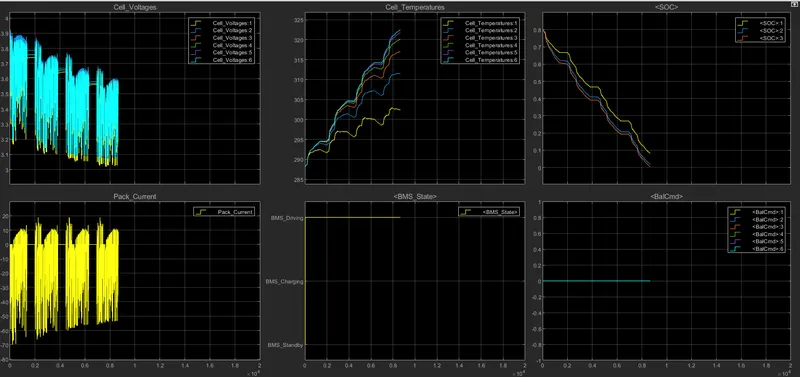
- The result shows that model stats wit its 80% SOC remaining and in driving state for 10000s but at 8600s the battery SOC reaches to 0% hence the simulation stops.
Test case3:

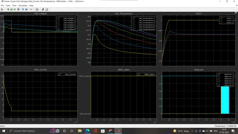
- This test case is for charging the battery.The plot shows that the bttery is in charging mode for entire period and reaches the max soc in a time.
- The coulomb counting is less accurate than kalman filtering.
Couloumb Counting:
The Coulomb counting method measures the discharging current of a battery and integrates the discharging current over time in order to estimate SOC . Coulomb counting method is done to estimate the SOC(t) , which is estimated from the discharging current,i(t) , and previously estimated SOC values,SOC(t-1) .
SOC is calculated by the following equation:
`SOC(t) = SOC(t-1)-((i(t)/Q))*deltat`
But there are several factors that affect the accuracy of Coulomb counting method including temperature, battery history, discharge current, and cycle life.
Modified coulomb counting:
To improve the Coulomb counting method, a new technique called modified Coulomb counting method is proposed. The modified Coulomb counting method uses the corrected current to improve the accuracy of estimation.
The corrected current is the function of discharging current. There is a quadratic relationship between the corrected current and discharging current of battery. By practice of experimental data, corrected current is calculated by the following form
`I_c(t)=k_2I(t)^2+K_1(t)I(t)+k_0`
where`k_2,k_1 and k_0` , and are constant values obtained from the practice experimental data.
In modified Coulomb counting method, SOC is calculated by the following equation:
The experimental results show that the accuracy of the modified Coulomb counting method is superior to the conventional Coulomb counting method.
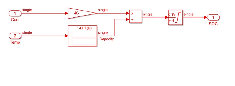
- Here coulomb counting is achived by integrating over a period of time,discrete integration is used and temperature is also considered.