Week 7 State of charge estimation
Report
AIM: State of Charge Estimation.
Objective:
- Simulate the 3 test cases from harness dashboard and write a detailed report on the results
- What is coulomb counting? Refer to the above model and explain how BMS implements coulomb counting for SOC estimation ?
1] Simulation of BMS with 3 different test cases from harness dashboard write a detailed report on the results.
Battery management system:
A battery management system (BMS) is any electronic system that manages a rechargeable battery (cell or battery pack), such as by protecting the battery from operating outside its safe operating area, monitoring its state, calculating secondary data, reporting that data, controlling its environment, authenticating it and / or balancing it.A battery pack built together with a battery management system with an external communication data bus is a smart battery pack. A smart battery pack must be charged by a smart battery charger.
Functions of BMS:
1] Monitor:
A BMS may monitor the state of the battery as represented by various items, such as:
- Voltage: total voltage, voltages of individual cells, or voltage of periodic taps
- Temperature: average temperature, coolant intake temperature, coolant output temperature, or temperatures of individual cells
- Coolant flow: for air or liquid cooled batteries
- Current: current in or out of the battery
2] Electric vehicle systems: energy recovery
The BMS will also control the recharging of the battery by redirecting the recovered energy (regenerative braking) back into the battery pack (typically composed of a number of battery modules, each composed of a number of cells).
3] Computation:
Additionally, a BMS may calculate values based on the below items, such as:
- Voltage: minimum and maximum cell voltage
- State of charge (SoC) or depth of discharge (DoD), to indicate the charge level of the battery
- State of health (SoH), a variously-defined measurement of the remaining capacity of the battery as % of the original capacity
- State of power (SoP), the amount of power available for a defined time interval given the current power usage, temperature and other conditions
- State of Safety (SOS)
- Maximum charge current as a charge current limit (CCL)
- Maximum discharge current as a discharge current limit (DCL)
- Energy [kWh] delivered since last charge or charge cycle
- Internal impedance of a cell (to determine open circuit voltage)
- Charge [Ah] delivered or stored (sometimes this feature is called Coulomb counter)
- Total energy delivered since first use
- Total operating time since first use
- Total number of cycles
- Temperature Monitoring
4]Communication:
The central controller of a BMS communicates internally with its hardware operating at a cell level, or externally with high level hardware such as laptops or an HMI.High level external communication are simple and use several methods:
Different types of serial communications.
- CAN bus communications, commonly used in automotive environments.
- Different types of wireless communications.
5] Protection:
A BMS may protect its battery by preventing it from operating outside its safe operating area, such as:
- Over-current (may be different in charging and discharging modes)
- Over-voltage (during charging), especially important for lead–acid and Li-ion cells
- Under-voltage (during discharging)
- Over-temperature
- Under-temperature
- Over-pressure (NiMH batteries)
- Ground fault or leakage current detection
6] Balancing:
In order to maximize the battery's capacity, and to prevent localized under-charging or over-charging, the BMS may actively ensure that all the cells that compose the battery are kept at the same voltage or State of Charge, through balancing.
The BMS can balance the cells by:
- Wasting energy from the most charged cells by connecting them to a load (such as through passive regulators)
- Shuffling energy from the most charged cells to the least charged cells (balancers)
- Reducing the charging current to a sufficiently low level that will not damage fully charged cells, while less charged cells may continue to charge (does not apply to Lithium chemistry cells)
MATLAB model of BMS:
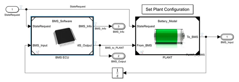
A] Battery Management System (BMS) ECU:
the above model consists of the following BMS algorithms:
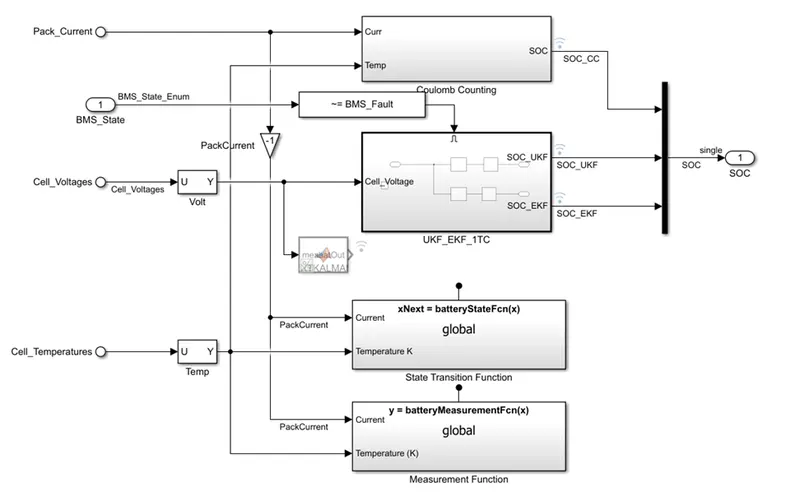
1] state of charge estimation using extended kalman filter,unscented kalman filter,coulomb counting:
in this BMS model the SOC is calculated bu using 3 diff.method:
- coulomb counting
- extended kalman filter
- unscented kalman filter
kalman filtering:
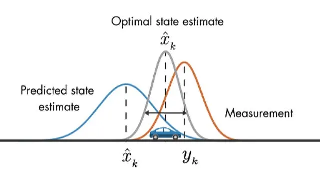
For statistics and control theory, Kalman filtering, also known as linear quadratic estimation (LQE), is an algorithm that uses a series of measurements observed over time, including statistical noise and other inaccuracies, and produces estimates of unknown variables that tend to be more accurate than those based on a single measurement alone, by estimating a joint probability distribution over the variables for each timeframe.
2] passive battery cell balancing:
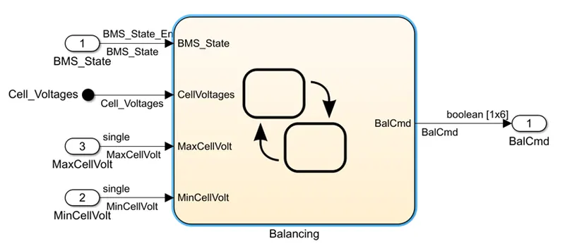
Passive balancing allows all batteries to have the same SoC, but it does not improve the run-time of a battery-powered system. It provides a fairly low cost method for balancing the cells, but it wastes energy in the process due to the discharge resistor.The high SoC cell is bled off (power is dissipated in the resistor) so that charging can continue until all cells are fully charged. Passive balancing allows all batteries to have the same SoC, but it does not improve the run-time of a battery-powered system.
When a battery pack is designed using multiple cells in series, it is essential to design the system such that the cell voltages are balanced to optimize performance and life cycles. Typically, cell balancing is accomplished by means of by-passing some of the cells during the charge or discharge cycles.The active cell balancing makes the voltage of each cell equal without wasting any energy. In a passive cell balancing, the voltage across each cell is made equal by wasting the energy through a resistor
cell balancing system:
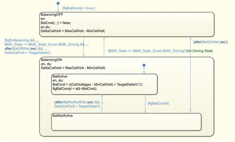
the cell balancing sysem continuosly monitors and measures the voltage differene between battery cell and the vehicle is not in driving and the difference between the cell voltage increases beyond a certain value the balncing start to happen.
pre-charging and contactor management:
When initially connecting a battery to a load with capacitive input, there is an inrush of current as the load capacitance is charged up to the battery voltage. With large batteries (with a low source resistance) and powerful loads (with large capacitors across the input), the inrush current can easily peak 1000 A. A precharge circuit limits that inrush current, without limiting the operating current.
A precharge circuit between a battery and its load is required if any of the following are issues:
- The load has input capacitors will be damaged by the inrush current
- The main fuse will blow if asked to carry the inrush current
- The contactors, if present, will be damaged by the inrush current
- The battery cells are not rated for the inrush current
Function:
The precharge circuit consists at the minimum of:
- A precharge resistor, to limit the inrush current (R1)
- A contactor (high power relay) across the precharge resistor (K2) to bypass the resistor during normal operation
- A precharge relay (K1), to keep the load from being powered through the precharge resistor when the system is off
- A contactor in line with the other end of the battery (K3) to isolate the load when the system is off
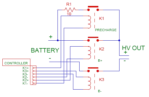
In the typical precharge circuit, the precharge resistor is on the positive terminal of the battery, though it could just as easily be on the negative terminal.While you are free to use any designators you wish, the ones in this schematic (R1, K2, K2 and K3) appear to be industry standard, so you are encouraged to use them as well.
operation:
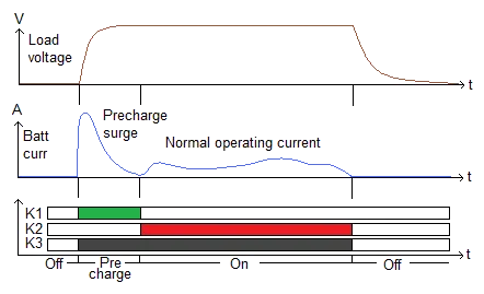
In the most basic form, the precharge circuit is operated as follows:
- Off: When the system is off, all relays / contactors are off
- Pre-charge: When the system is first turned on, K1 and K3 are turned on, to precharge the load, until the inrush current has subsided
- On: After precharge, contactor K2 is turned on (relay K1 may be turned off to save coil power)
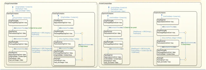
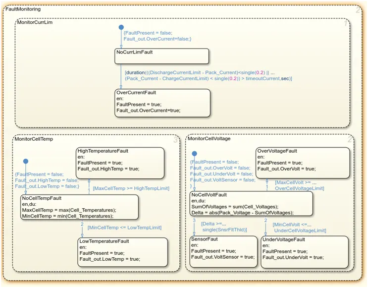
4] fault management:- over/under voltage,over current,over temperature:
5] charge and discharge current limit calculation:
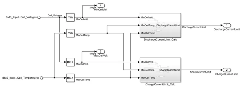
- the charge and dscharge calculation is also a part of the fault management and protection function performed by the BMS to restrict the operation in safe working points within the limits.
- the voltage level of 6 cell is given as input from which the minimum voltage is used to find the max discharge current of the battery and similarly the max.voltage of the cell is used to find the max charging current for the battery.
discharging current limit subsystem:
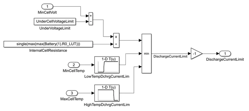
the minimum voltage is then fed to the discharege current subsystem where minimum the diff.between cutoff voltage and cell minimum voltage is used to find the maximum instataneuos discharge current using the resistance of the cell.the minimum discharge current is then chosen by considering the cell instateneous temp,resistance,and voltage of the cell.
charging current limit subsystem:
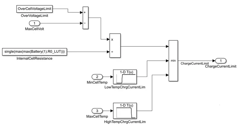
the maximum charging current is found based on the maximum instateneous voltage which is then compared to the max safe voltage of the cell.also the cell instateneous temp,resistance,and voltage are taken into consideration.
B] plant:
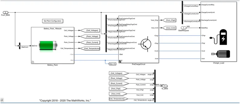
the plant model consist of 3 subsystem consisting of the following:
1] battery pack:
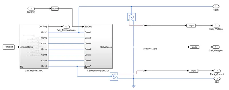
- the battery pack consist of a module with 6 cell connected in series along with the cell balancing circuit.
- the voltmeter is connected in parallel to the battery pack and an ammmeter is connected in series to the negative of the battery
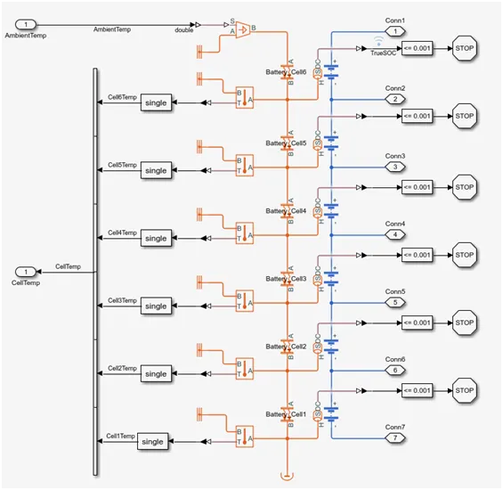
cell module:
- it shows 6 cell connected in series along with the temp. sensor the simulation is stopped when the SOC of the cell drops below 0.00
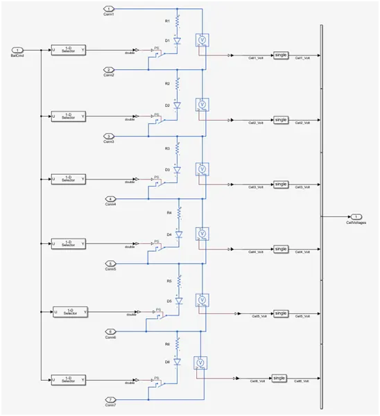
cell balancing circuit:
- here we use only passive cell balancing tech. as it is comparativaly cheaper and less complex than the active cell balancing tech.
- in the cell balancing circuit we use only a resister in parrallel to dissipate the charge stored in the form of heat this is controlled using a voltage sensor which checks when to stop balancing to stop over-discarging.
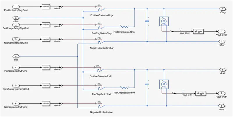
2] pre-charge circuit:
- the precharge circuit is used in order to prevent the current rush while charging and discharging the battery and to prevent the spark generation,the wiring and the components from the sudden flow of high current.
- the resister is connected in series to limit the current flow and a capacitor is connected to prevent the voltage ripple.at first -ve of the battery is connected and then the capacitor is charged via resistor and a the end step positive terminal is connected.
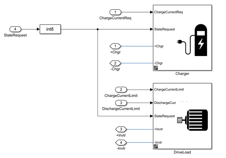
3] charging/discharging load:
- the charging or the load is applied using based on the user input given is state request given as input in the subsystem.
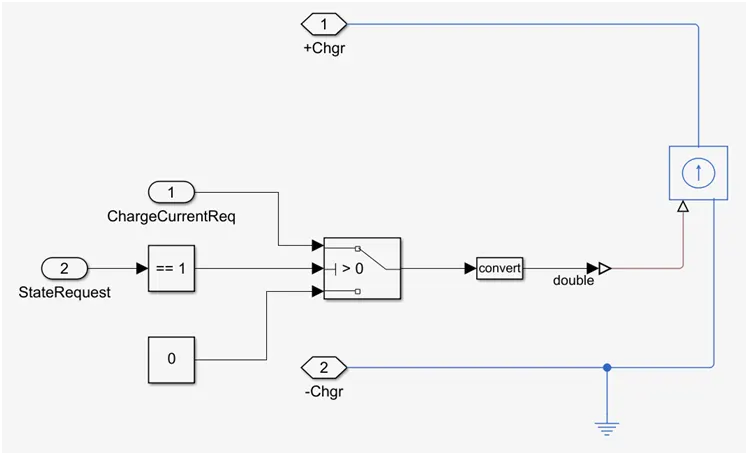
charging:
- when the state input for charging is I then the battery is charged via a controlled current source and the amt is charge is mapped to a data stored under the variable 'charge current req'
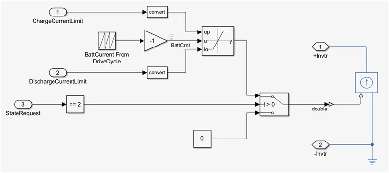
discharging:
- here the charge given by the battery is considered as positive and the charge given to the battery is considered as negative.
- the state requirement is checked and the current profile for discharge is made as a repeating sequence from a remaped data in the variable 'battcrnt'. the battery is discharged using a controlled current source.
simulate the different test cases:
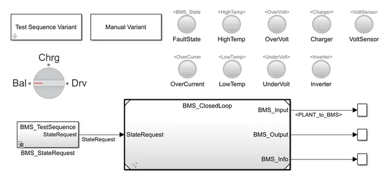
this the BMS close loop harness dashboard to design and test this algorothm and this project also includes files for:
- li-ion battery cell parameter estimation
- battery pack with 6 cells in series and 96 cell in series
- simulink test files with test cases to tes state machine logic
- linking requirements to models
1] test sequence 1:
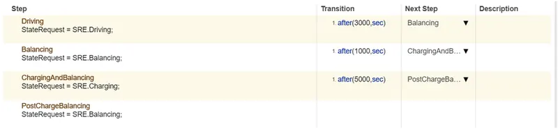
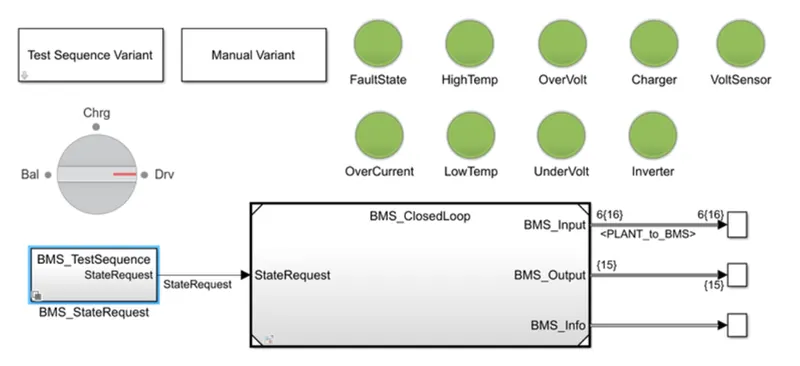
the simulation is run for 20,000 sec in which the first 3,000 sec is the discharging or the driving mode then the next 1000 sec are in balancing or standby mode then for 5000 sec in charging and discharging mode and afterwards the in standby or balancing mode.
output:
graphs:
comments:
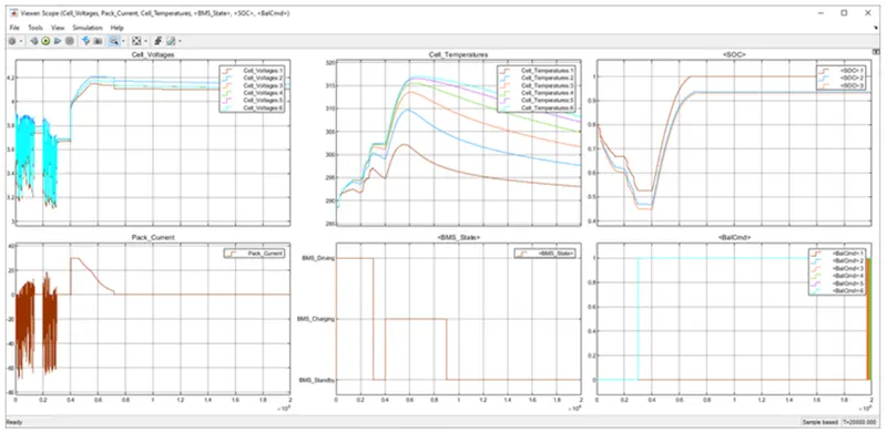
- the first plot with cell- voltage displays the voltage o all 6 cells connected in the series. while the first 3000 sec.the voltage of the cell drops as the battery discharging and during standby periods the voltage stabilize as the cell balancng gets activated and even due to cell inherit behaviour.then while charging the cell voltage increases and while the cell balancing the voltage stabilizes.
- the second plot with pack current represents the current drawn and given to the battery while charging and discharging it is also seen that while charging frst the current remains constant and then its drops its changes in constant voltage mode.
- the third plots the cell temp. of all indvidual cell and we can see then while charging and discharging the cell temp increases.
- the fourth plot shows the input state as per the given state input.
- the fifth plot shows the SOC of the entire pack by diff. method of calculation the SOC curve decreases as we discharge the battery and increases while charging.
- sixth plot shows the cell balancing command for all six cell. the 1st cell is having the lowest voltage does not need balancing thus we can see that all the other cell signal have a magnitude of 1 where as the 1st cell signal is at zero magnitudes.
2] test sequence 2:
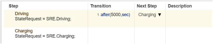
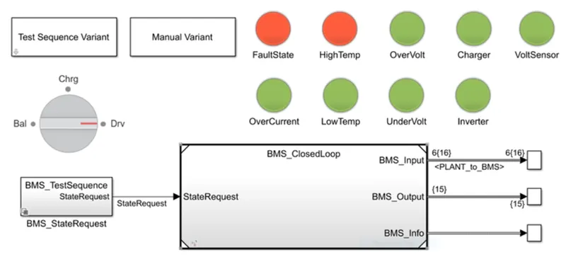
the simulation is to run for 20,000 sec in which the first 5000 sec is the discharge or the driving mode then the rest of the time is set to charge the battery.
output:
graphs:
comments:
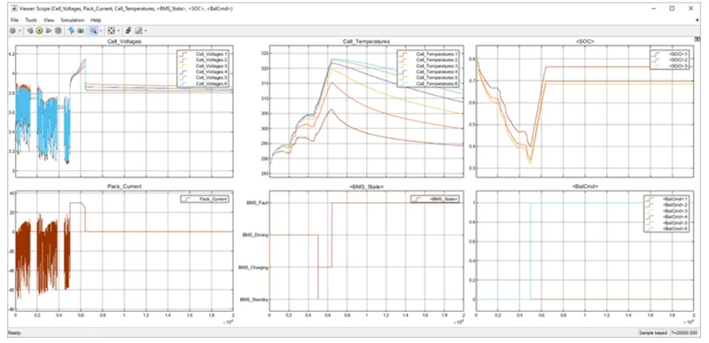
- the first plot with cell- voltage displays the voltage o all 6 cells connected in the series. while the first 5000 sec.the voltage of the cell drops as the battery discharging and then while charging the cell voltage increases and while the cell balancing the voltage stabilizes.
- the second plot with pack current represents the current drawn and given to the battery while charging and discharging it is also seen that while charging frst the current remains constant and then its drops its changes in constant voltage mode.
- the third plots the cell temp. of all indvidual cell and we can see then while charging and discharging the cell temp increases.at about 6000 sec the cell emp of the 6th cell increases to about 323.15K and battery is send the fault state.
- the fourth plot shows the input state as per the given state input until the fault accours at about 6000sec.
- the fifth plot shows the SOC of the entire pack by diff. method of calculation the SOC curve decreases as we discharge the battery and increases while charging.the battery is charged 70-75% and stops charging once the fault occurs.
- sixth plot shows the cell balancing command for all six cell. the 1st cell is having the lowest voltage does not need balancing thus we can see that all the other cell signal have a magnitude of 1 where as the 1st cell signal is at zero magnitudes.the cell balancing starts when the battery start to charge and at the onset of the fault the battery charging is stopped but the balancing happens.
3] test sequence 3:
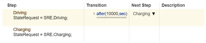
the simulation is to run for 20,000 sec in which the first 5000 sec is the discharge or the driving mode then the rest of the time is set to charge the battery.
output:
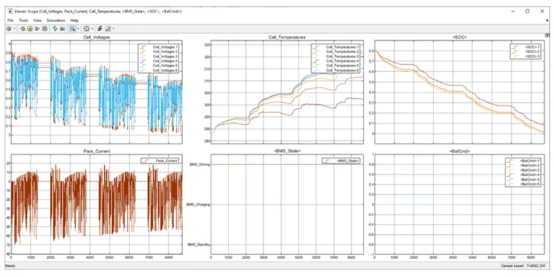
graphs:
comments:
- the first plot with cell- voltage displays the voltage o all 6 cells connected in the series. the cell voltage keeps on dropping as the battery keeps on discharging up to zero state of charge and the simulation is stopped.
- the second plot with pack current represents the current drawn and given to the battery while charging and discharging here we can see that battery repeats the charging and discharging pattern as explained above in the charging and discharging load.
- the third plots the cell temp. of all indvidual cell and we can see then while charging and discharging the cell temp increases.
- the fourth plot shows the input state as per the given state input,the simulation only runs in dscharging mode and when SOC reaches zero the simulation is stopped at about 8692 sec.
- the fifth plot shows the SOC of the entire pack by diff. method of calculation the SOC curve decreases as we discharge the battery and increases while charging.here the battery keeps on discharging as the regenerative charging is very less.
- sixth plot shows the cell balancing command for all six cell. the cell balancing does not take place as the simulation runs only in a driving state.
2] coulomb counting:
Coulomb counting is a technique used to track the state of charge of a battery pack.its works by integrating the active flowing current (measured in amps) over time to derive the total sum of energy entering or leaving the battery pack. this produces a capacity that is typically measured in amp-hours[Ah]
The coulomb counting method measures the discharging current of a battery and integrates the discharging current over time in order to estimate SOC.its done to estimate the SOC(t) which is estimates from the discharging current,I(t) and previously estimated SOC values SOC(t-1). SOC is calculated by the following eq.
SOC(t)=SOC(t-1) + [I(t)/Qn]*dt
where,
SOC(t)= state of charge at estimated time.
I(t)= discharging current.
Qn= nominal battery capacity.
Implementation of coulomb counting for SOC estimation in the BMS:
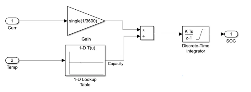
- The discharge current signal is convered from the physical system using a gain block.
- The gain block is integrated by 1/30*3600 is applied to the integrated signal which gives us the discrete data.
- The temprature data is divide by using a look-up table with the discharge current rate.
- The output is then integrated with a discrete-time integrator block with a sample time 0.1sec to calculate the SOC of the battery pack.