Week 7 State of charge estimation
Model based Battery Management system(BMS):
The given simulation model(Sorce:Mathwork.com) is to analyze how the battery management system reacts as per the user input and also find the faults occure with the battery pack.
The primary function of the BMS is to protect the battery cells from damage caused by being overcharged or over-discharged. Additionally, the BMS calculates the remaining charge, monitors the battery’s temperature, monitors the battery’s health and safety by checking for loose connections and internal shorts. The BMS also balances the charge across the cells to keep each cell functioning at maximum capacity.
If it detects any unsafe conditions, the BMS shuts the battery down to protect the lithium-ion cells and the user.
Functions of BMS
- Monitor cell voltage and temperature
- Estimate battery state-of-charge (SOC) and state-of-health (SOH)
- Limit power input and output for thermal and overcharge protection
- Control the battery charging profile
- Balance the state-of-charge of individual cells
- Isolate the battery pack from source and load when necessary
BMS colsed-loop harness dashboard:
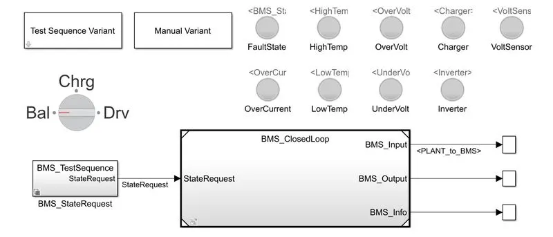
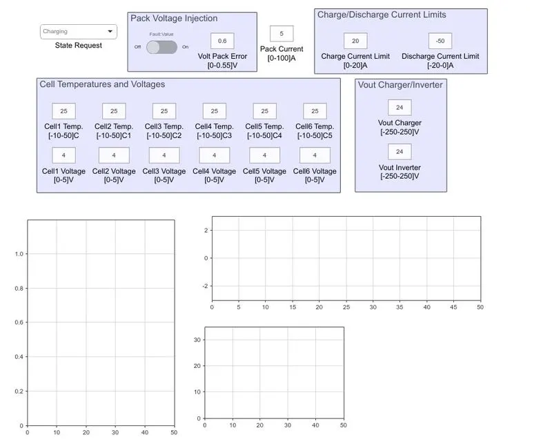
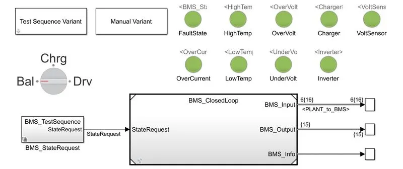
The above simulink model has a number of element which used to simulate the BMS system. The major elements are BMS closed loop which has the battery pack system.
Basically it has three sequence. It consists of 6 cell module.
The above dashboard has a set of indicators which is used to find the error in the system which are,
- High temperature
- Over voltage
- Fault state
- Over current
- lower temperatire
- Charger
- Voltage sensor
- Invertor
- Under voltage
Closed loop:
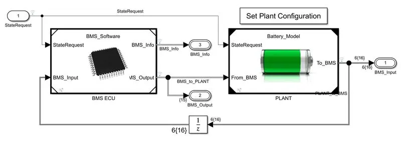
The above system reperest the plant model which includes ECU and Plant subsystems.
The ECU(elecronic control unit) is based on PCB board and software but in plant model in based on actual battery system.
BMS ECU:
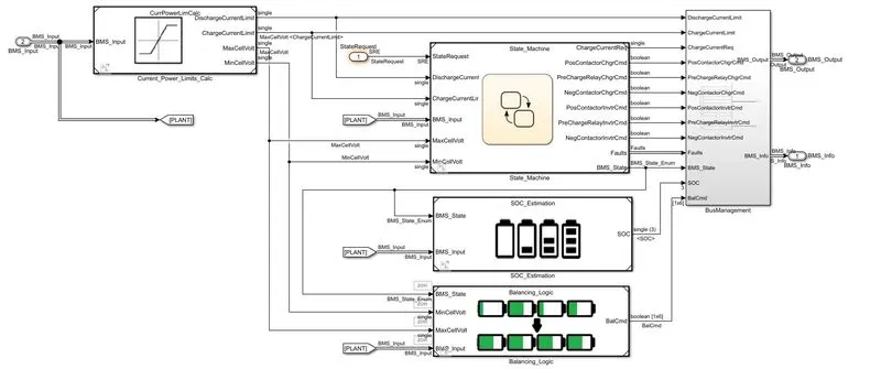
The above ECU model has a set of subsystem and stateflow charts helps to perform some logics.
Battery plant:
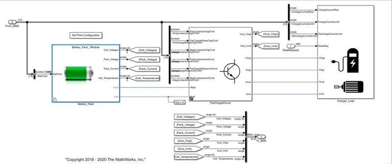
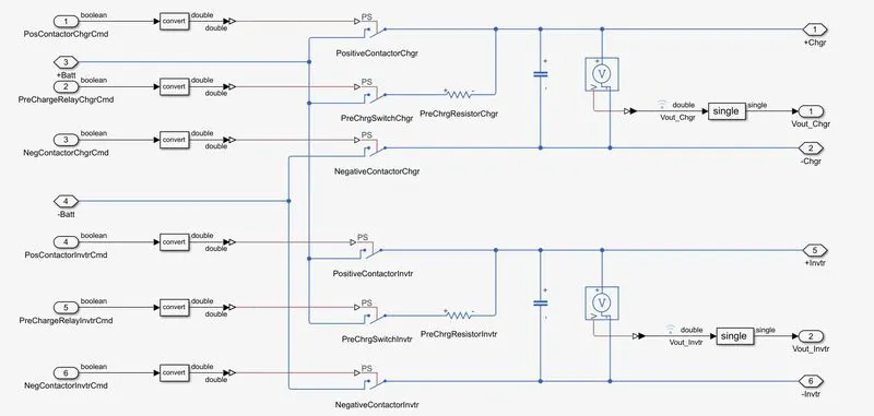
It consists of battery pack , load, precharging circuit and etc. to perform the BMS simulation. The precharing circuit consists a set of block circuit to perform the desired logic actions. The precharging circuit is given below.
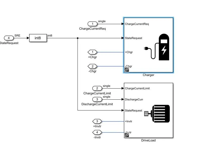
The battery plant basically has a two kind of loads that is charger load and motor load.
To provide the load condition to the system the below subsystem is reqired.
The BMS system has a three kind of modes which is
- Driving
- Balencing
- Standby
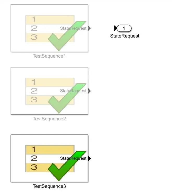
We are going to analyze these three kind of modes in this simulation
Case1:
Result:
The above model is for the firse case and the results for that is given below,
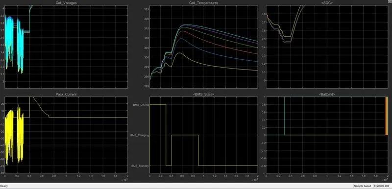
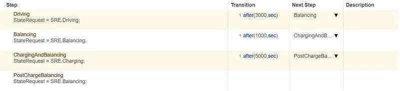
We can clearly see that for the first 3000 seconds the battery is being driven by the load then 1000 seconds it was in standby condition then 5000 seconds it's getting charged then remaining to 20000seconds it was in standby condition
So according to the above feed the results shows the behavior of the battery. For voltage it fluxuates to 4000 seconds then it goes upto 4.2V then it remain constant. Same for the current also it goes upto 30A then it remain constant.
For battery temperature it raises to 315 over time period then it cooldown for a certain temperature.The SOC get drainded for 4000 seconds then it raises to 100% because it's getting charged.
Case 2:
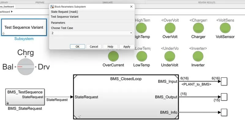
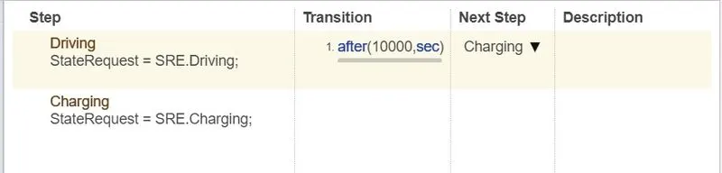
The condition for the case two is given below
Result
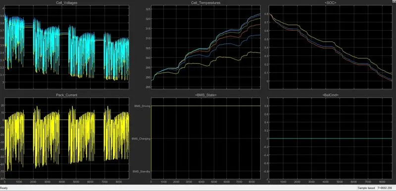
- The condition two feeds were very simple it's getting drained over the period when it's getting fully discharge
- We can clearly see that the volatge and current getting fluxuated over the period and it has three intermideate stable condition.
- The maximum voltage is upto3.9V and minimum was 3.1V.
- For current it goes upto maximum of 19A.
- In case of temperature it's getting increse over the period of time.
- The charging state of a battery is drainded until it's goes to 0.
Case 3:
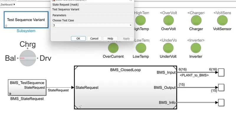
The feed conditions were given below

Results:
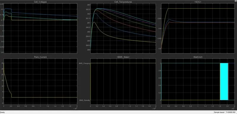
- In previous case we saw about the constant discharge condition but in this case we see about the constant charge condition.
- Like previous case but it's getting charged over the period of time there would be no load.
- So the voltage getting fluxuate initially but it remain almost constant same as for current also it moves towardes to 0 and remains contant at 0.
- The temperatue get raised initially because of sudded charge then it get normalise to a certain limit.
Coulomb counting:
The Coulomb counting method measures the discharging current of a battery and integrates the discharging current over time in order to estimate SOC . Coulomb counting method is done to estimate the , which is estimated from the discharging current, , and previously estimated SOC values, . SOC is calculated by the following equation:
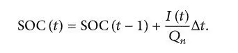
But there are several factors that affect the accuracy of Coulomb counting method including temperature, battery history, discharge current, and cycle life
Methods:
| Direct measurement | (i) Open circuit voltage method |
| (ii) Terminal voltage method | |
| (iii) Impedance method | |
| (iv) Impedance spectroscopy method |
| Book-keeping estimation | (i) Coulomb counting method |
| (ii) Modified Coulomb counting method |
| Adaptive systems | (i) BP neural network |
| (ii) RBF neural network | |
| (iii) Support vector machine | |
| (iv) Fuzzy neural network | |
| (v) Kalman filter |
It depends on the recording of the current noise only. The signal is filtered with a high-pass filter with a cut-off frequency of 0.01 Hz. The filter may be either analogue (although the implementation of a good-quality 0.01 Hz analogue filter is difficult) or digital. The absolute value of the measured current samples is then summed over time. A steep slope is taken as an indication of rapid corrosion, although it is not possible to calibrate this in terms of an estimated corrosion rate.
Since the energy storage systems have been highlighted in portable electronics and hybrid electric vehicle applications, the estimate accuracy of SOC becomes increasingly important. In recent years, many scholars have done a lot of research on SOC estimation. The estimate accuracy has improved constantly, and it can be expected that intense research and development efforts are already on track. In order to further improve SOC estimates, combined with some literatures, anticipated improvements for the further research
This method is aimed at calculating coulombs or the quantity of electric charge, which is derived from current multiplied by the time necessary for the charge to flow. To measure the remaining capacity or SOC of a battery, you can add coulombs to the initial capacity in case of charging or take them away when you discharge the battery.
Current integration is a widespread method, but its accuracy depends on some factors. First off, you should know the correct measure of the initial SOC that serves as a reference point. You can get this by fully charging or discharging a battery. So if you want to use this technique, you need to allow for regular resetting of the battery SOC to 100% in your BMS design.
Reference:
- https://www.hindawi.com/journals/isrn/2013/953792/
- https://www.integrasources.com/blog/battery-management-system-bms-state-charge-and-state-health/