Week 7 State of charge estimation
1)
Test Harness:
In software development, a test harness is a collection of software and test data used by developers to unit test software models during development. A test harness will specifically refer to test drivers and stubs, which are programs that interact with the software being tested. Once a test harness is used to execute a test, they can also utilize a test library to generate reports.
Test harnesses are used in two main areas, automation, and integration testing. Test harnesses in automation testing will use test scripts (commonly written in JAVA, python, and Ruby) to the software testing process. Once a test is executed, the results can be used to generate a test report. A test harness in integration testing is used to test the integration of two sets of code so they can interact with one another. Integration testing will ensure both sets of code are working as predicted, in a single unit. Test cases will also be written and executed with an automation script.
Some benefits of test harnesses include the automation and testing process, generation of test reports, supporting debugging modes, and earlier identification of bugs.
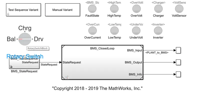
When simulation will start, the model will be in driving condition. After 3000 seconds it will be in standby mode and after 1000 seconds it will be in charging mode. Now by running the simulation.
Test sequence 1:
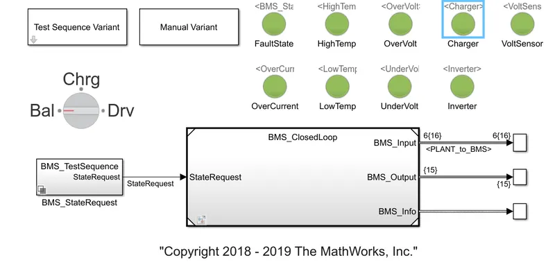
Dashboard for Test case 1
Here all the indicators are in green color which says there are no errors after simulation. The sequence model and output can be seen below,
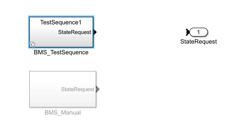
Test Sequence Block
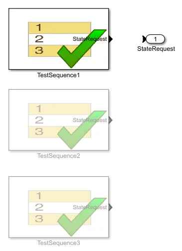
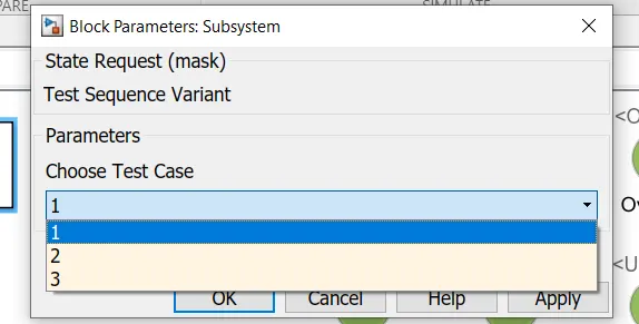
Setting up the Test sequence 1 block for simulation
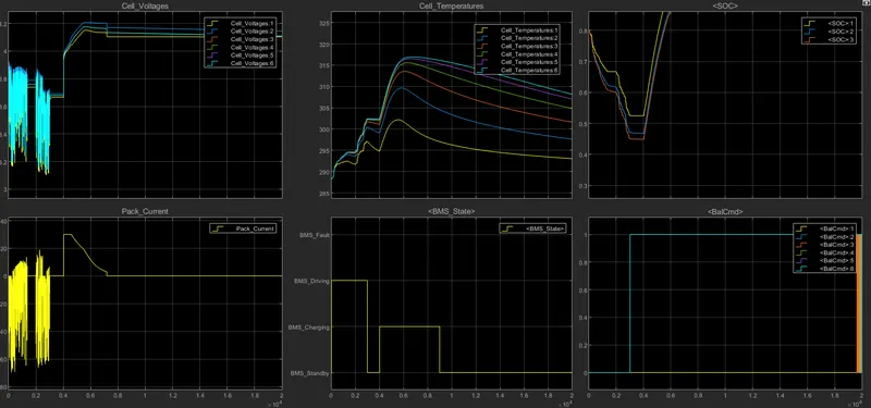
Results for the Test Sequence 1
From the plot, we can see the vehicle is initially in a driving state, and charging was done to 90% and after charging it reaches standby mode. It can be seen in the BMS state plot. Battery temperature increases while driving and charging the vehicle. Battery voltage was increased to 4.2V while charging. The current plot shows the value of current supplied to a vehicle while driving. SOC decreased up to 50% in driving conditions and it was increased while charging.
Test sequence 2:
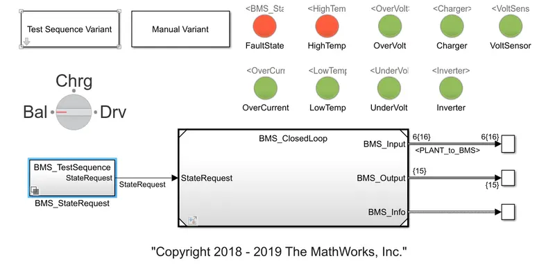
Dashboard for Test case 2 , here we can observe failure in BMS and high temperature at battery pack.
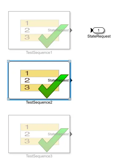
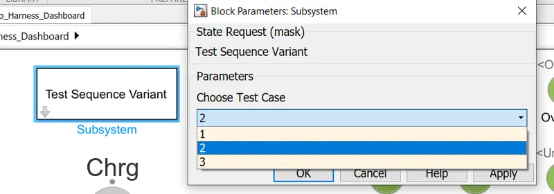
Setting up the Test sequence 2 block for simulation
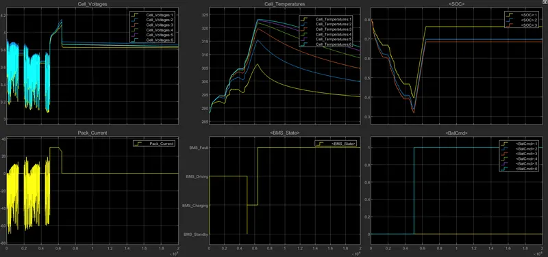
Results for the Test Sequence 2
Here a fault condition occurred in the second case. So even after charging was started, the SOC didn't even increase rather it continue to decrease.
Test Sequence 3:
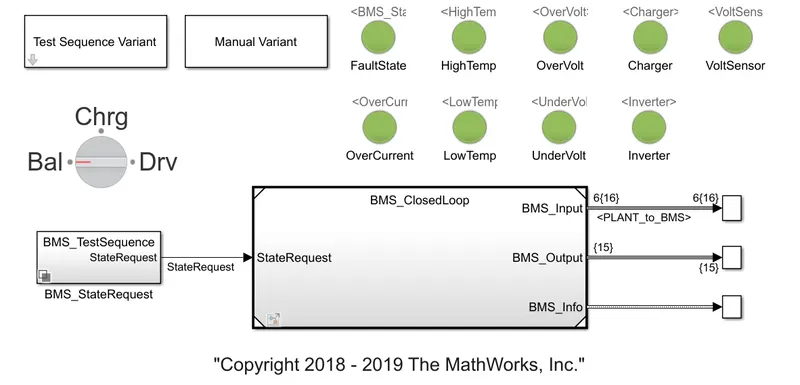
Dashboard for Test case 3
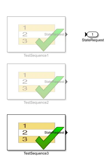
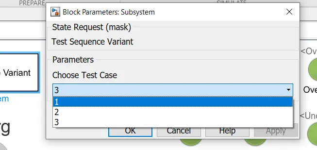
Setting up the Test sequence 3 block for simulation
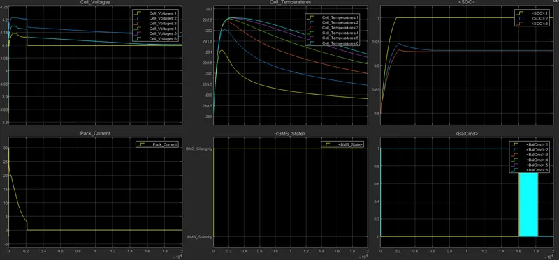
Results for the Test Sequence 3
From the above 3 cases, we observe that charging takes place because SOC was 80% at first, and then SOC increases to 100% in the first 2000 seconds then SOC remains constant at 100%.
2)
BMSystem:
A battery management system (BMS) is technology dedicated to the oversight of a battery pack, which is an assembly of battery cells, electrically organized in a row x column matrix configuration to enable the delivery of a targeted range of voltage and current for a duration of time against expected load scenarios. The oversight that a BMS provides usually includes:
- Monitoring the battery
- Providing battery protection
- Estimating the battery’s operational state
- Continually optimizing battery performance
Here, the term “battery” implies the entire pack; however, the monitoring and control functions are specifically applied to individual cells, or groups of cells called modules in the overall battery pack assembly. Lithium-ion rechargeable cells have the highest energy density and are the standard choice for battery packs for many consumer products, from laptops to electric vehicles. While they perform superbly, they can be rather unforgiving if operated outside a generally tight safe operating area, with outcomes ranging from compromising the battery performance to outright dangerous consequences. The BMS certainly has a challenging job description, and its overall complexity and oversight outreach may span many disciplines such as electrical, digital, control, thermal, and hydraulic.
BMS working:
Battery management systems do not have a fixed or unique set of criteria that must be adopted. The technology design scope and implemented features generally correlate with:
- The costs, complexity, and size of the battery pack
- Application of the battery and any safety, lifespan, and warranty concerns
- Certification requirements from various government regulations where costs and penalties are paramount if inadequate functional safety measures are in place
There are many BMS design features, with battery pack protection management and capacity management being two essential features. Battery pack protection management has two key areas:
Electrical protection, which implies not allowing the battery to be damaged via usage outside its Safe Operating Area(SOA), and
Thermal protection, involves passive and/or active temperature control to maintain or bring the pack into its Safe Operating Area.
State Of Charge(SOC):
SOC estimation is a fundamental challenge for battery use.
The SOC of a battery, which is used to describe its remaining capacity, is a very important parameter for a control strategy. As the SOC is an important parameter, which reflects the battery performance, so accurate estimation of the SOC can not only protect the battery, prevent over-discharge, and improve the battery life but also allow the application to make rational control strategies to save energy.
However, a battery is a chemical energy storage source, and this chemical energy cannot be directly accessed. This issue makes the estimation of the SOC of a battery difficult. Accurate estimation of the SOC remains very complex and is difficult to implement because battery models are limited and there are parametric uncertainties.
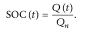
The SOC is one of the most important parameters for batteries, but its definition presents many different issues [5]. In general, the SOC of a battery is defined as the ratio of its current capacity () to the nominal capacity (). The nominal capacity is given by the manufacturer and represents the maximum amount of charge that can be stored in the battery. The SOC can be defined as follows:
The classification of these SOC estimation methods are of four categories:
(a)Direct measurement: It uses the physical battery properties, such as the voltage and impedance of the battery.
(b)Hybrid methods: The hybrid models benefit from the advantages of each SOC estimation method and allow a globally optimal estimation performance.
The literature shows that the hybrid methods generally produce a good estimation of SOC, compared to individual methods.
(c)Book-keeping estimation: It uses discharging current as of the input and integrates the discharging current over time to calculate the SOC.
(d)Adaptive systems: The adaptive systems are self-designing and can automatically adjust the SOC for different discharging conditions.
Various new adaptive systems for SOC estimation have been developed.
Among all these, under Book-keeping estimation we have the Coulomb Counting Method.
Coulomb Counting Method:
The Coulomb counting method measures the discharging current of a battery and integrates the discharging current over time in order to estimate SOC. Coulomb counting method is done to estimate the SOC(t), which is estimated from the discharging current, I(t), and previously estimated SOC values, SOC(t-1). SOC is calculated by the following equation:

But there are several factors that affect the accuracy of the Coulomb counting method including temperature, battery history, discharge current, and cycle life.
Modified Coulomb Counting Method:
To improve the Coulomb counting method, a new technique called the modified Coulomb counting method is proposed. The modified Coulomb counting method uses the corrected current to improve the accuracy of estimation.
The corrected current is the function of discharging current. There is a quadratic relationship between the corrected current and discharging current of the battery. By the practice of experimental data, the corrected current is calculated by the following form:

where k2,k1, and k0 are constant values obtained from the practice experimental data.
In the modified Coulomb counting method, SOC is calculated by the following equation:

The experimental results show that the accuracy of the modified Coulomb counting method is superior to the conventional Coulomb counting method.
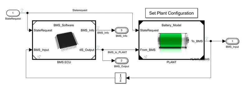
The subsystem of BMS ECU is
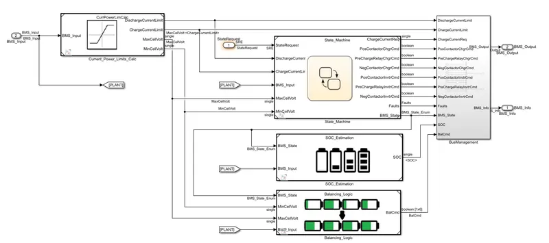
The SOC estimation block contains
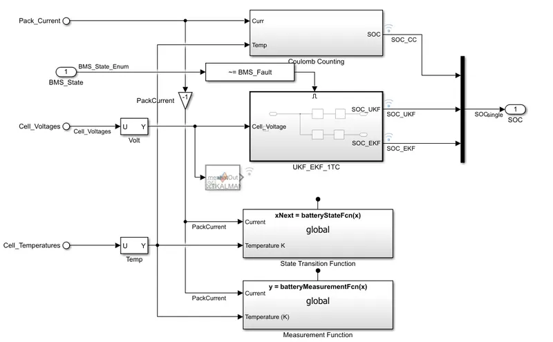
Above mentioned coulomb counting block have the
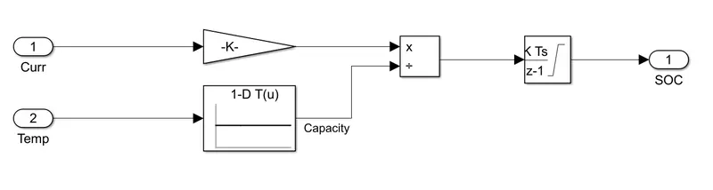
This contains the Discrete-Time Integrator which is connected to multiply and divide block, this integrator is fed by 1-D look-up Table and a gain of 1/3600
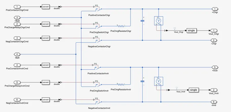
Above is the typical Pre-Charge circuit contains combination if PreChargeResistor and PreChargeSwitch, Positive - Negative Contactor blocks.
- This system does the estimation by coulomb counting equation mentioned above.
- Advantage of coulomb counting method is its simplicity and low computational cost.
- Temperature and current from the battery is given as inputs.
- Current signal is given to a gain block and temperature is given to capacity since it varies according to temperature.
- These inputs are given for integration where current will be integrated with respect to time.
- This outout is given to another block where it is divided by capacity.
- Hence the SOC is estimated.