Project
BAJAJ ATV VEHICLE
Aim: To determine and analyze the ATV(autonomous vehicle) powered by the bajaj through MATLAB Simulink.
Components: Signal Builder, Generic engine, Gear, Engine sensor, CVT, Vehicle body, and related references.
CVT block contains a Variable gear ratio, Ideal rotational motion sensors, terminator, inertia shafts, reference.
Vehicle body block contains Double - shoe break, Rear and front wheels, Vehicle body, Wind velocity, and Inclination.
Theory: We have a Simulink model of a vehicle where it was designed with all the necessary gauges and connections to simulate by varying the parameters for analyzing the machine fully.
There are four types of transmission in this system, they are:
- Nominal
- Continuous variable
- Automatic
- Semi-automatic
When we talk about a vehicle the main aspect we see in it will be stability on various surfaces, this can be inferred as the machine we design should be able to move in all-terrain conditions. For this, we need to analyze some parameters in order to use the ATV vehicle. To do this, we will be analyzing the whole machinery dividing it into blocks for easy analysis.
Signal builder: This is a block in which we can modify the signal as per our requirement, here we used it for transmission of the vehicle.
Generic Engine: It is a general internal combustion engine that includes spark-ignition and diesel. This is used to run our model and to transmit the power.
Gear: This is the part installed in vehicles by which the transmitted power from the engine to axle varies, the variation in gear ratio makes the vehicle run smoothly in any terrain. Normally in any vehicle, the 1st gear and reverse gear have much power capacity to drive. And here we change the gear relative to the speed of the vehicle.
Engine sensor: This helps in sensing the RPM, velocity, and angular displacement parameters acting on the engine at every instant.
Vehicle body: It is a block for body mass, aerodynamic drag, road incline, and weight distribution between axles due to acceleration and road profile. The vehicle can have the same or a different number of wheels on each axle.
CVT: A CVT, or continuously variable transmission, seamlessly changes through an unending range of effective gear ratios while you drive, whereas other kinds of mechanical transmissions offer a fixed number of gear ratios and have hard shifts between each as explained by Certified Transmission Repair. CVT transmission systems are also known as single-speed, shiftless, and stepless transmissions. These systems work through a pulley system. It includes a variable gear ratio which defines the ratio of input to output angular shaft velocities and we also have shaft inertia for the system to perform.
Here we try to figure out the performance of the vehicle by varying the parameters and also we will try to analyze the speed- torque curve.
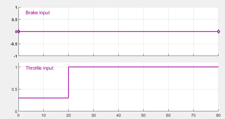
The above shows the input signal from a signal builder.
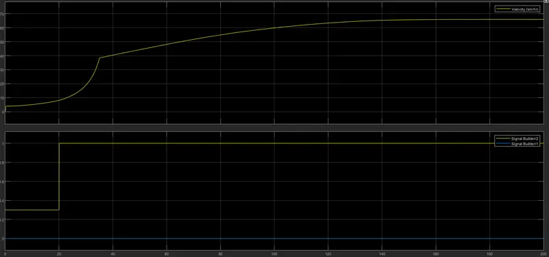
The above figure shows the, change in velocity applied, throttle, and brake input.
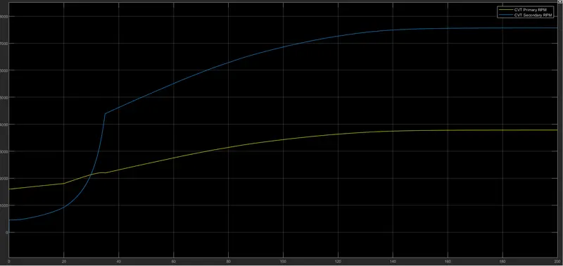
In the above figure, we can even observe the CVT primary/secondary RPMs.
Here we can change so many parameters like torque, velocity, brake input, throttle, mass of the body, inertia acting on the body, etc.,
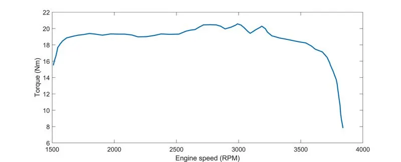
The above gives us the relation between the speed & torque for the terrain vehicle at various inputs given to it.
- And from the simple gear block, we can manipulate the gear(NF/NB) that are applied to the system at the prescribed velocity.
- And all these outputs can be understood by observing the Gauges that are connected, even to a layman.
- Here we added some workspace blocks in order to initialize some of the data required to run the model from the workspace.
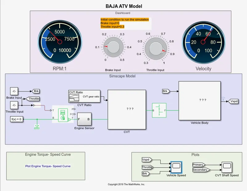
The gauges in the above figure display the amount of throttle & brake applied to the system, there will be a variation in velocity when brake input is applied which describes the behavior of vehicles on different terrains.
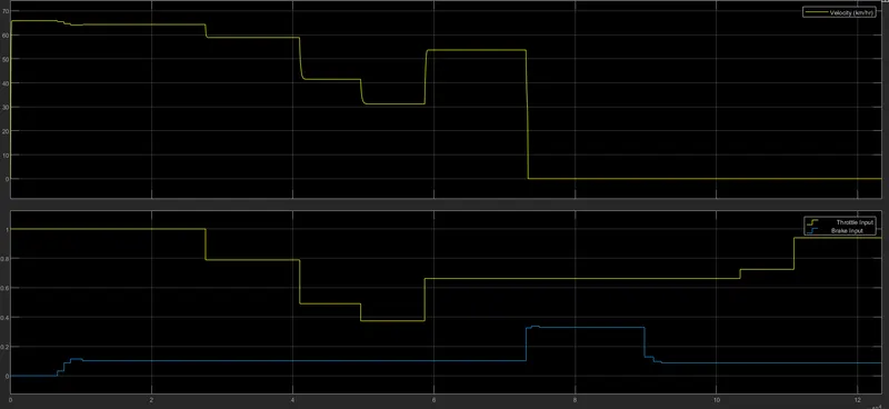
In the above figure we can clearly observe the output waveforms of each parameter we changed (brake, throttle)and related change in velocity waveform.
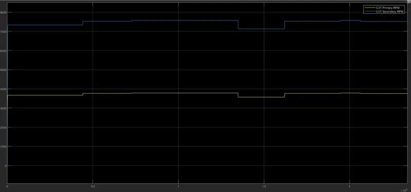
And from this figure we can analyze the CVT primary/secondary RPM with change in the parameters mentioned above.The step wise ups and downs denote the uncertainty of vehicle at different inputs, we can also observe the consistency it is maintaining in every condition.
NOW WE WILL SEE SOME OF THE LOOKUP TABLES IN THE MODEL TO UNDERSTAND THE MODEL BETTER
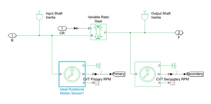
The above figure is the lookup table of CVT ratio block where brake input is given to the rotational sensor(CVT Primary RPM) to determine the velocity of the vehicle by rotation(RPM) of the wheels and gear ratio's force is given to another rotational sensor(CVT Secondary RPM) to determine the angular velocity of the wheel.
- Here CVT primary is given a constant brake input whereas gear ratio follower is given to CVT Secondary which determines the speed of the vehicle for given brake input.
Operation:
The system is operated in the following sequence,
Brake & Throttle --> Generic Engine --> CVT (Primary & Secondary) --> Simple Gear --> Vehicle Body --> Wheels (connected to Double-shoe brake)
- The throttle is given to the engine which produces the required force given to CVT ratio, transmits the power to simple gear which indicates you to change gear if necessary.
- By taking the gear and brake inputs the vehicle body responds and transmits the required input to the wheels, simultaneously the brake shoe which experiences the brake input will give input to the mechanical ports of the connected wheels.
- The inertia blocks connected to the brake shoe and CVT blocks produce the required inertia for the system's performance.
By various conditions and varying parameters we conducted and prepared a technical report of the BAJAJ ALL TERRAIN Vehicle through sysytem-level simulation.