Week 7 State of charge estimation
1. Test cases from harness dashboard:
Model of BMS_ClosedLoop_Harness_Dashboard: To evalute the system's response to a potentialy unsafe condition for example temperature, voltage or current outside the recommended limits.
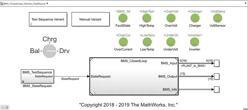
- Inside BMS_ClosedLoop subsytem; there is BMS ECU and plant as shown below:
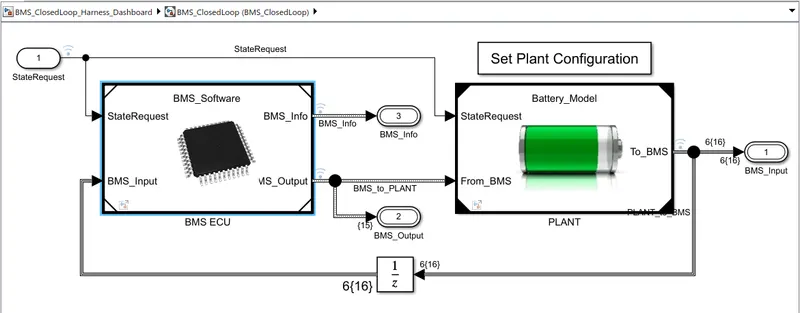
- Inside BMS ECU system:
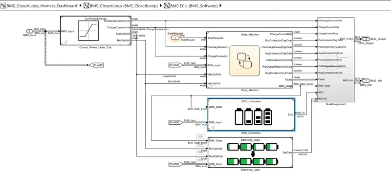
- BMS ECU unit have SOC estimation system, Balancing Logic and State machine.
- SOC is estimated by three methods: Coulomb Counting, UKF SOC and EKF SOC which gives ouput as SOC1,SOC2 and SOC3.
- Balancing Logic balancing the voltage levels of cells of battery pack and gives command -BalCmd.
- State machine which represents active and inactive states depending upon conditions. It has four parallel states. First one have driving, standby, charging states, second one checks the temperature, voltage and current safe values and third and fourth stages defined contactors ON/OFF.
- Inside Plant unit:
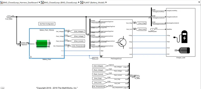
- Plant unit consist of Battery pack, Precharge circuit and charger load, where PreCharge circuit used to limits the inrush current without limiting the operating current.
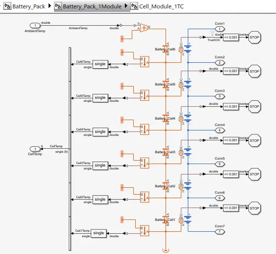
- For analysis, Battery pack of 6 cells are used which are connected in series and exchange heat with one another as shown below:
Test case-01:
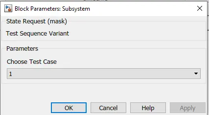
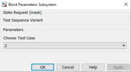
- To select first test case, goto Test Sequence Varient as shown below:
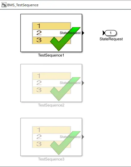
- Goto BMS_StateRequest and check the states of test case as shown below:
- States of Test case-01:
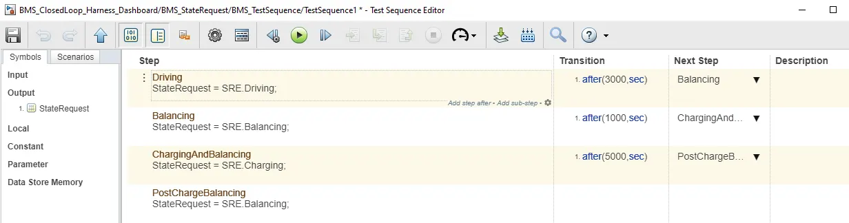
- For first 3000 secs, Veehicle is in driving mode, then for next 1000 sec, it is in balancing mode i.e. at standstill and after 5000secs vehicle is at standstill and charging both.
- Result of First test case:
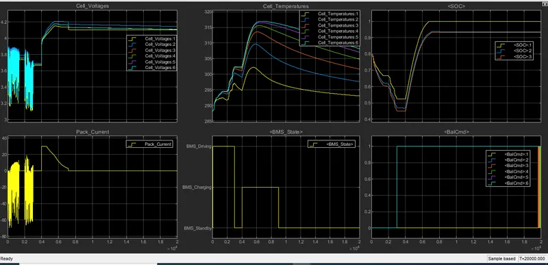
- During First 3000secs, vehicle is in driving mode; there is variations appears in current and voltage; temperature of all six Li-ion cells start increasing and SOC decreases.
- BMS state plot shows the states of vehicle.
- After 3000secs, Cell voltage increases and there is high peak current due to sudden change in stage.
- In thid mode: charging and balancing, Temperature of all the cells start decreasing and SOC starting increasing and then become stable.
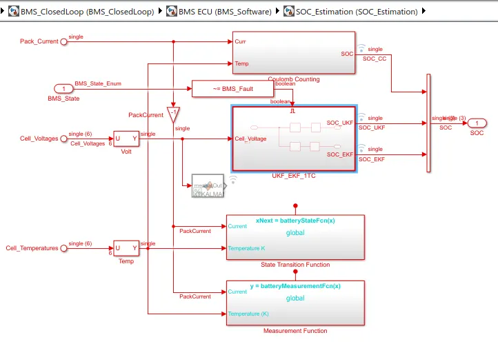
- SOC is estimated by three methods: Coulomb Counting, UKF SOC and EKF SOC. Here SOC1,SOC2 and SOC3 are graphs of these three methods.
- BalCmd plot shows whether cells are balanced or not; Command 0 shows all cells are balanced till 3000 secs and after that cell 06 become imbalanced.
- Voltages and current also become stable in charging and standstill mode.
Test case-02:
- By selecting second test case from Test Sequence Varient; goto BMS_StateRequest and check the states of test case:
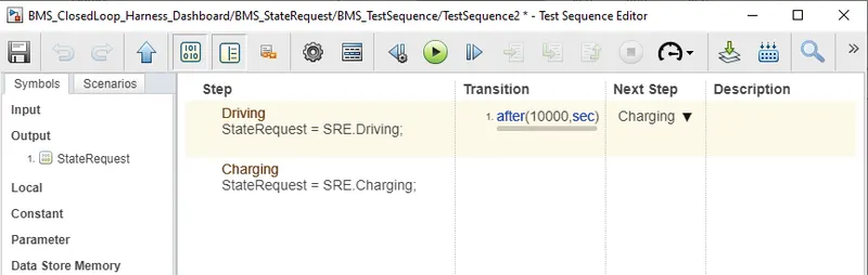
- In second test case, Vehicle is in driving mode for 10000secs and then in charging.
- Result of 2nd case:
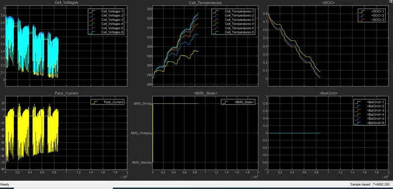
- For 10,000 secs, there is variations in current as well as voltages of cells.
- Temperature start increasing of all 6 cells. cell-06 acquires more temperature at the end.
- SOC of by three methods decreasing from 80%.
- All cells are balanced as Balcmd is zero for all cells.
Test case-03:
- By selecting third test case from Test Sequence Varient; goto BMS_StateRequest and check the states of test case:
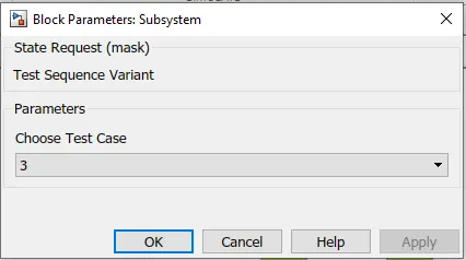
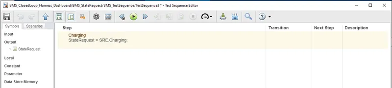
- In third test case, Vehicle is only in charging mode.
- Result of 3rd case:
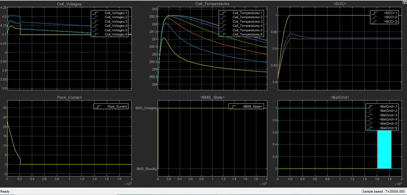
- At the starting of charging there is some variations in voltage and current but after 2000 secs current comes to Zero A and voltages became stable.
- Temperature of all cells decreases where cell-06 has high temperature and cell-01 has low temperature.
- SOC1 estimated by Coulomb Counting achieved 100% where as SOC2 and SOC3 which are estimated by UKF SOC and EKF SOC are between 90 to 95%.
- BMS state graph shows charging state .
- BalCmd: At starting. Cell-06 is high(1) means it is unbalanced and cell-01 is at low(0) means it is balanced.
2. Coulomb Counting:
- Coulomb counting is a technique used to track the State of Charge of a battery pack. It works by integrating the active flowing current (measured in amps) over time to derive the total sum of energy entering or leaving the battery pack. This produces a capacity that is typically measured in Amp-Hrs.
- From above model: BMS_closedLoop<<BMS ECU<<SOC_Estimation<<Coulomb Counting
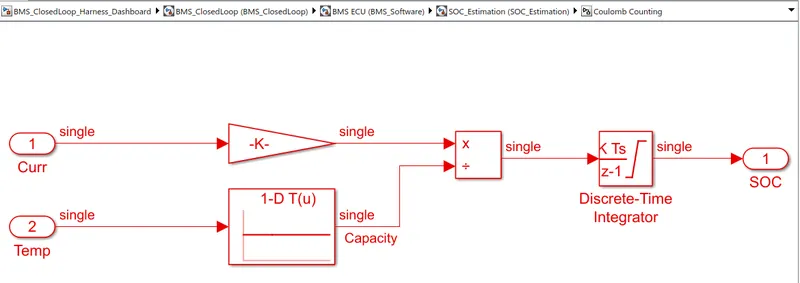
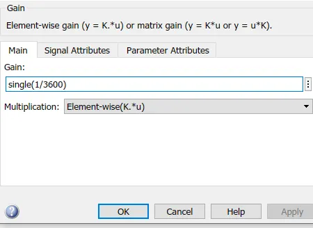
- In this Current of Ampheres is converted into Ah capacity by dividing 3600( using gain block) which is shown below:
- This Ah is divided by capacity and further integrated which provides charge calculation.
- Benefit of this method is its simplicity and very low computational cost.
- Its drawback includes the accumulation of current sensor error and its inability to recover from a wrong initial condition because of the lack of feedback from voltage measurements.
Reference: https://in.mathworks.com/matlabcentral/fileexchange/72865-design-and-test-lithium-ion-battery-management-algorithms