Week -2
Problem Statement:
- Make a Simulink model of Doorbell using solenoidblock with the following details:
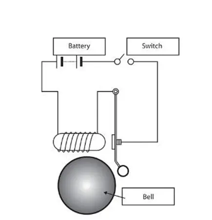
In the above arrangement, when the switch is closed the electromagnet receives electrical power from the battery and pulls the metal arm to hit the bell producing sound.
Create a situation where the switch is closed for 2 seconds and then released. Observe the physical movement of the plunger.
Solution:
Working of Electric Bell:
A bell works with the principle of working of electromagnetism.
When the switch is pushed on, the circuit gets completed and the current starts flowing through the U-shaped electromagnet which creates a magnetic field in the core. This attracts the iron armature.
When the armature moves towards the electromagnet, the hammer strikes the gong and the bell rings.
As the armature moves towards the electromagnet, the contact with the adjustment screw breaks which breaks the closed circuit and stops the current. Now, when there is no current there is no electromagnetism and the armature returns to the original position. This making and breaking of the circuit of the electromagnet continue as long as the button remains pressed.
Input Condition:
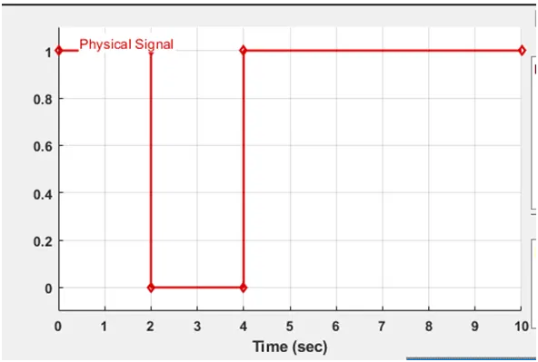
- When Switch is closed, Signal has high value (1).
- Then for 2 sec, Switch is released and Signal has low value (0).
Blocks Used:
- Signal Builder: To generate the signal according to Input condition given.
- Simulink-PS converter: Converts the Simulink input signal to a Physical Signal.
- Switch: The block represents a switch controlled by an external physical signal. If the external physical signal PS is greater than the threshold, then the switch is closed, otherwise the switch is open.
Here output of Signal builder is given to External physical signal PS of Switch.
- Voltage Source: This block models a voltage source with DC, AC and noise components.
Here DC voltage is 50V and all other components are Zero.
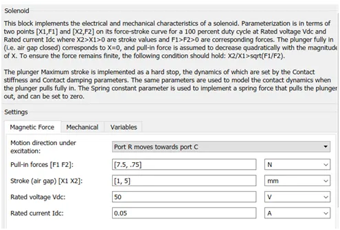
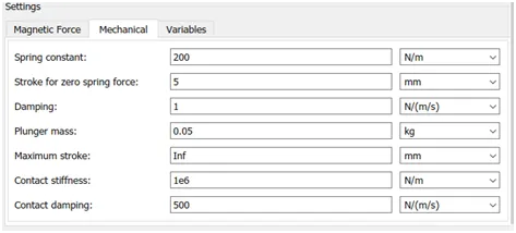
- Solenoid: This block implements the electrical and mechanical characteristics of a solenoid.
- Electrical reference: The Electrical Reference block represents an electrical ground. Electrical conserving ports of all the blocks that are directly connected to ground must be connected to an Electrical Reference block.
- Ideal Translational Motion Sensor: This block measures velocity or displacement in a mechanical translational network. The sensor is ideal since it does not account for inertia, friction, delays, energy consumption, and so on.
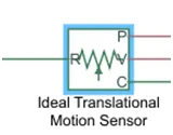
The physical signal ports V and P report the velocity and position, respectively, of port R relative to port C. The measured velocity is positive when the velocity at port R is greater than the velocity at port C.
- Mechanical reference: The Mechanical Translational Reference block represents a reference point, or frame, for all mechanical translational ports. All translational ports that are rigidly clamped to the frame (ground) must be connected to a Mechanical Translational Reference block.
- Solver Configuration: Each physical network represented by a connected Simscape block diagram requires solver settings information for simulation. The Solver Configuration block specifies the solver parameters that a model needs to begin simulation.
- PS-Simulink Converter: Converts the input Physical Signal to a Simulink output signal.
- Scope: The output block that shows signal with respect to time in X-axis.
Simulink Model:
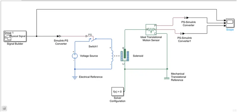
Physical Signal from Signal Builder is connected to Switch and this Switch closed or released according to Input condition. Circuit is completed when Switch closes and 50 V DC Supply is given to Solenoid and due to electromagnetic action, Plunger moves and this movement is detected by Translational Motion Sensor which is shown by Scope block.
Output:
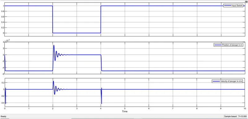
This shows displacement and velocity of plunger at m=0.05kg, k=1*10^6 N/m and c=500 N/(m/s).
Problem Statement:
- Use a thermistor to sense the temperature of a heater & turn on or turn off the fan as per the below conditions:
Temperature source: 20 °C from 0 to 10 seconds, 27 °C from 10 to 30 seconds, 23 °C from 30 to 50 seconds
Fan conditions: ON if the temperature above 25 °C, OFF otherwise
Solution:
Thermistors: A thermistor is a resistance thermometer, or a resistor whose resistance is dependent on temperature. The term is a combination of “thermal” and “resistor”. It is made of metallic oxides, pressed into a bead, disk, or cylindrical shape and then encapsulated with an impermeable material such as epoxy or glass.
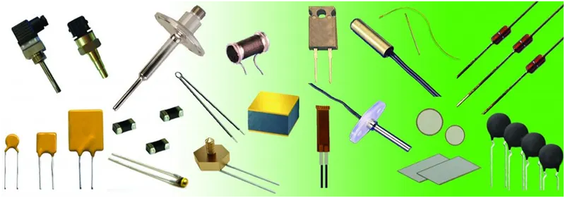
There are two types of thermistors: Negative Temperature Coefficient (NTC) and Positive Temperature Coefficient (PTC). With an NTC thermistor, when the temperature increases, resistance decreases. Conversely, when temperature decreases, resistance increases. This type of thermistor is used the most.
A PTC thermistor works a little differently. When temperature increases, the resistance increases, and when temperature decreases, resistance decreases. This type of thermistor is generally used as a fuse.
Input and Output Condition:
- Input: 20°C from 0 to 10 sec
27°C from 10 to 30 sec
23°C from 30 to 50 sec
- Output: Fan is ON if Temperature>25°C,
Else OFF
Blocks Used:
- Clock: The Clock block outputs the current simulation time at each simulation step.
- MATLAB function: With a MATLAB Function block, we can write a MATLAB function for use in a Simulink The MATLAB function we create executes for simulation and generates code.
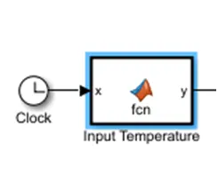
Here clock and MATLAB function used to meet INPUT conditions.
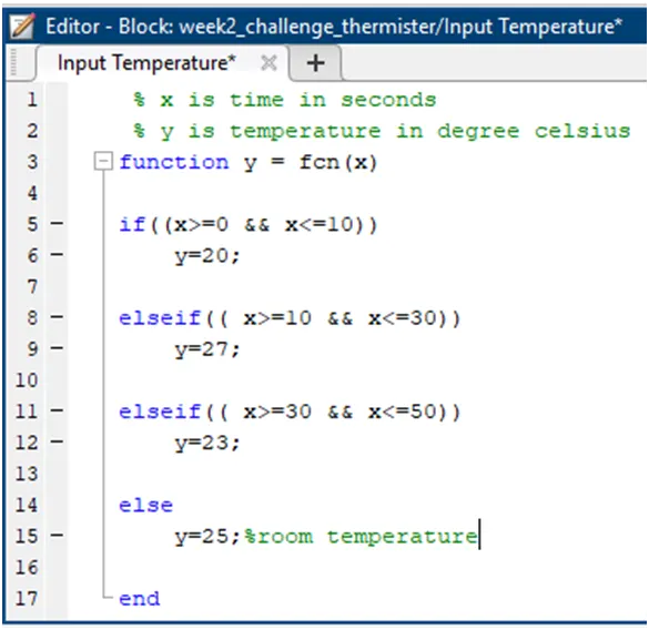
Double-clicking the MATLAB Function block opens its editor, where we write the MATLAB function:-
- Controlled Temperature Source: This block represents an ideal energy source in a thermal network that can maintain a controlled temperature difference regardless of the heat flow rate.
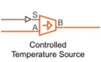
The temperature difference is set by the physical signal port S. A positive temperature difference causes the temperature at port B to be greater than the temperature at port A.
- Thermistor: This block represents an NTC thermistor using the B-parameter equation. The resistance at temperature T is given by
R(T) = R0*exp(B*(1/T-1/T0))
where R0 is the Nominal resistance at the reference temperature T0, and B is the Characteristic temperature constant.
The temperature T of the thermistor is governed by the equation
m*c*dT/dt = Q
where Q is the net heat flow into port A, m is the mass and c is the lumped specific heat capacity.
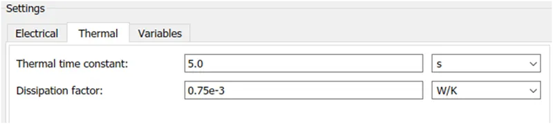
The thermal mass m*c is calculated from the Thermal time constant t_c and the Dissipation factor K_d using the equation
m*c = K_d*t_c.
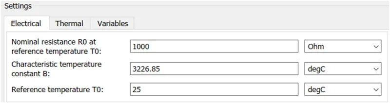
Electrical and thermal parameters of thermistor:
All temperature values are converted into degC as physical input in degC.
- Thermal Reference: This block represents a reference point in a thermal network where the temperature is equal to absolute zero.
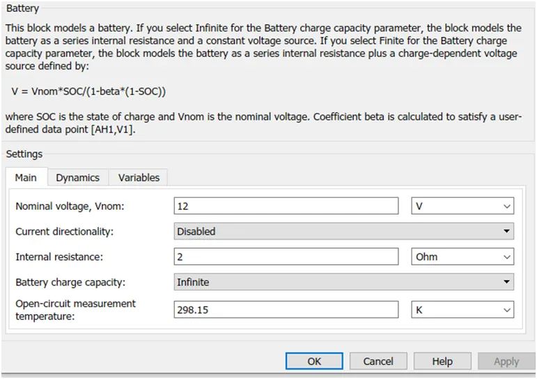
- Battery: Battery is storage device which provides the required voltage based on the parameters given.
- Voltage Sensor: The Voltage Sensor block represents an ideal voltage sensor, that is, a device that converts voltage measured between two points of an electrical circuit into a physical signal proportional to the voltage. It should connect in parallel only.
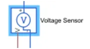
Connections + and – are electrical conserving ports through which the sensor is connected to the circuit. Connection V is a physical signal port that outputs the measurement result.
- Resistor: Resistor which provides opposing nature of current in the circuit.
- Electrical Reference: Electrical reference port. A model must contain at least one electrical reference port (electrical ground).
- Constant: Provide a constant output value.
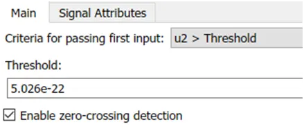
- Switch: Pass through input 1 when input 2 satisfies the selected criterion; otherwise, pass through input 3. The inputs are numbered top to bottom (or left to right). The first and third input ports are data ports, and the second input port is the control port. The criteria for control port 2 are u2 >= Threshold, u2 > Threshold or u2 ~= 0.
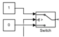
Here u2>threshold which is 5.026e-22(voltage across resistor)
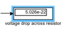
- Display: Display input values.
Here it is used to display voltage across resistor.
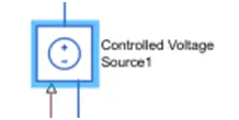
- Controlled Voltage Source: The block represents an ideal voltage source that is powerful enough to maintain the specified voltage at its output regardless of the current passing through it. The output voltage is V = Vs, where Vs is the numerical value presented at the physical signal port.
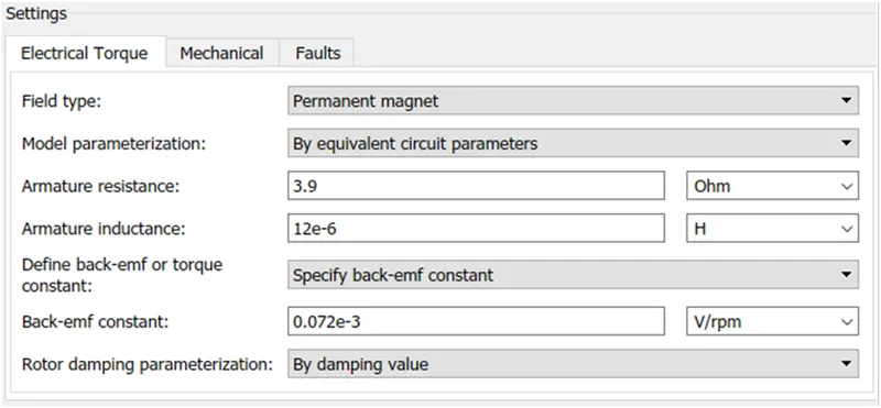
- DC Motor: DC motor is electromechanical block that takes electrical input and provides mechanical rotational output. This block represents the electrical and torque characteristics of a DC motor.
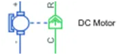
When a positive current flows from the electrical + to - ports, a positive torque acts from the mechanical C to R ports. Motor torque direction can be changed by altering the sign of the back-emf or torque constants.
Parameters of DC motor:
- Ideal Rotational Motion Sensor: This block measures angular velocity or angle in a mechanical rotational network. The sensor is ideal since it does not account for inertia, friction, delays, energy consumption, and so on.
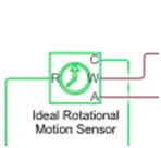
The physical signal ports W and A report the angular velocity and angle, respectively, of port R relative to port C. The measured angular velocity is positive when the angular velocity at port R is greater than the angular velocity at port C.
- Mechanical Rotational Reference: This block represents a mechanical rotational reference point, that is, a frame or a ground. Use it to connect mechanical rotational ports that are rigidly affixed to the frame (ground).
- Simulink-PS Converter: Converts the Simulink input signal to a Physical Signal.
- PS-Simulink Converter: Converts the input Physical Signal to a Simulink output signal.
- Solver Configuration: Defines solver settings to use for simulation.
- Scope: The output block that shows signal with respect to time in X-axis.
Simulink Model:
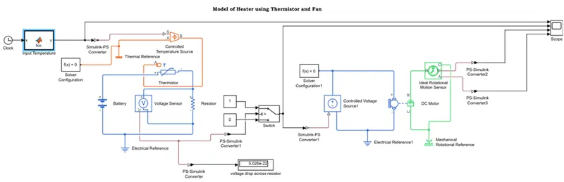
This model uses fundamental thermal, mechanical and electrical components for Heater using Thermistor and Fan/DC motor.
According to input conditions, Input Temperature signal is generated using MATLAB function and clock. Then this signal is fed to Controlled Temperature Source which maintains the controlled temperature difference and this temperature difference passes to thermistor. Thermistor is connected with battery of 12V and resistor across which voltage sensor is connected in parallel to calculate the threshold value which shows on Display i.e. 5.028e-22 (or 25°C). This threshold value also compared using Switch which gives digital output as 1 or 0 according to threshold value.
The output of Switch is given to controlled voltage source which powers the DC motor. Angular displacement and velocity is sensed by using Ideal rotational motion sensor whose output is connected to Scope.
Output:
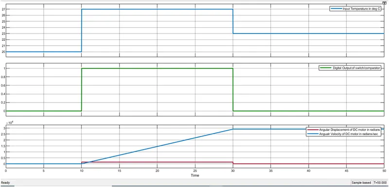
So, DC motor/Fan is activated from 10 to 30 seconds and temperature in this duration is 27°C which is higher than threshold.