Week 7 State of charge estimation
Aim:
- Simulate the 3 test cases from harness dashboard and write a detailed report on the results.
- What is coulomb counting? Refer to the above model and explain how BMS implements coulomb counting for SOC estimation ?
Solution:
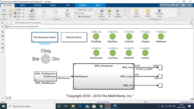
We need to download the model using the link provided in Question. We select harness dashboard from project file which we have downloaded. the model is shown below:
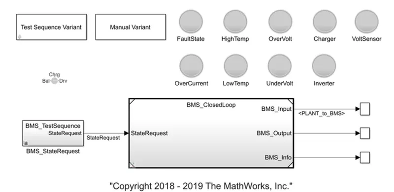
Now we have 3 test case to be simulated and get a detailed report of it.
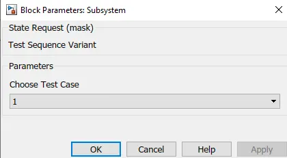
A. First test case: To move to first test case we click on test sequence variant and there we select 1 and press ok the same is shown below.
Next we need to click on BMS_state Request block. We will get a chart specifing the timing of different processes. The same is shown below:
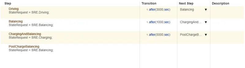
From observation it is clear that Driving is for 3000 Sec Followed by Balancing for 1000 Sec Then Charging and Balancing For 5000 Sec And last As Post Charging Balancing.
The we click on run and we get the following output graphs as shown below:
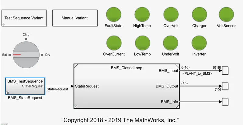
As there is no No fault found so the LEDs are green in test no. 1.
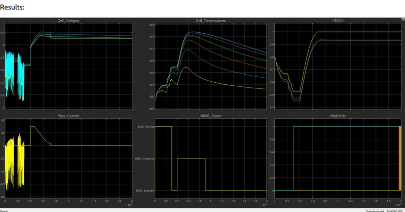
The first graph shows individual cell voltage the voltage is between 3.2 to 3.7 for first 3000 Sec this fluctuation is because of driving mode of vehicle. Then from 3000 to 4000 it is balancing and cell voltage is maintained at 4V. From 4000 to 8000 it is charging and balancing thus the voltage rises to 4.2V.
The Pack current graph, From 0 to 3000 the current decreases because of consumption and the current value comes -60A. Then from 3000 to 4000 the cell is balancing hence current moves to 0A. From 4000 to 8000 this is charging so current goes to 30A. Here after comes post charging balancing where current comes to 0A.
The cell temperature graph, the cell temperature reduces during driving mode the for balancing the temperature were reducing and as charging started the cell temperature again increases suddenly the latter at post charging balancing the temperature reduces.
The BMS state graph shows three mode of vehicle i.e. 0 to 3000 driving followed by standby till 4000 and then charging till 8000 sec.
The SOC graph shows that during driving the SOC comes from 80% to 45%, then during standby it remains constant at 45% and during charging the SOC goes to 100% and remain constant.
The last graph shows the cell balancing mode i.e from 3000 to 8000 the cell is balanced.
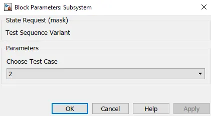
B. Second test case: To move to Second test case we click on test sequence variant and there we select 2 and press ok the same is shown below.
Next we need to click on BMS_state Request block. We will get a chart specifing the timing of different processes. The same is shown below:
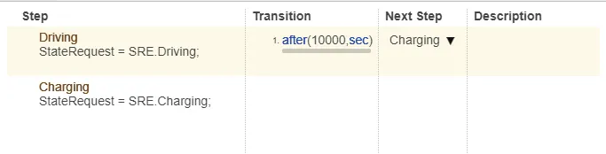
From observation it is clear that for 10000 sec it is driving mode.
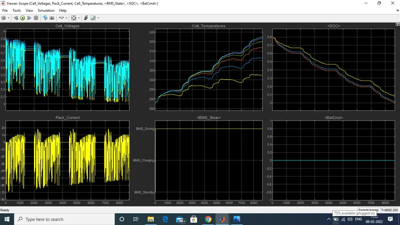
The Cell voltage is between 3.9 to 3.2V contineouslly due to driving and charging.
During driving the pack current moves from 0 to -60A and during charging moves to 10A As shown.
The cell temperaure is increasing due to driving mode And the BMS shows driving mode from 0 to 10000 sec.
The SOC reduces from 80 to 0% because there is no charging mode in between. Though the driving mode is till 10000 sec but the SOC becomes 0% at 9000 sec and hence the drive mode is till 9000 sec.
C. Third test case: To move to Third test case we click on test sequence variant and there we select 3 and press ok the same is shown below.
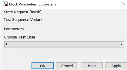
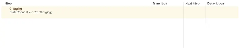
Here in this case ther is only one state i.e. charging so for complete 20000 sec charging will take place.
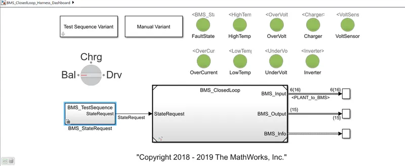
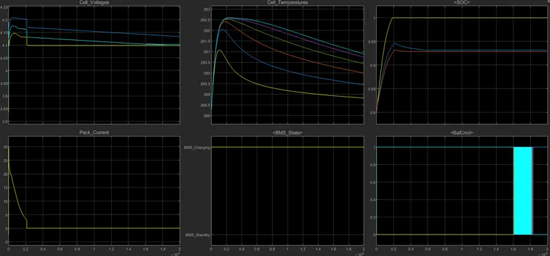
The cell voltage varries till 2000 second then remains constant.
At starting cell pack current goes to 30A and then comes to 0 at 2000 sec.
As charging is taking place the SOC moves from 80 to 100%.
Above given are the 3 test cases and the output graph of the model.
Coulomb Counting method: Coulomb counting is a technique used to track the SOC of a battery pack. It works by integrating the active flowing current (measured in amps) over time to derive the total sum of energy entering or leaving the battery pack. This produces a capacity that is typically measured in Amp-hour.
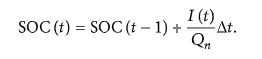
The Coulomb counting method measures the discharging current of a battery and integrates the discharging current over time in order to estimate SOC [20]. Coulomb counting method is done to estimate the SOC(t) , which is estimated from the discharging current I(t) , and previously estimated SOC values,SOC(t-1) . SOC is calculated by the following equation:
But there are several factors that affect the accuracy of Coulomb counting method including temperature, battery history, discharge current, and cycle life.
Modified coulomb counting method: To improve the Coulomb counting method, a new technique called modified Coulomb counting method is proposed. The modified Coulomb counting method uses the corrected current to improve the accuracy of estimation.
The corrected current is the function of discharging current. There is a quadratic relationship between the corrected current and discharging current of battery. By practice of experimental data, corrected current is calculated by the following form:

where k1,k2 and k0 , and are constant values obtained from the practice experimental data.
In modified Coulomb counting method, SOC is calculated by the following equation:
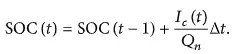
The experimental results show that the accuracy of the modified Coulomb counting method is superior to the conventional Coulomb counting method.
To compute the SOC of the battery we need to make a model:
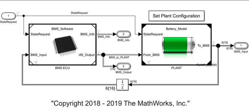
BMS algorithm models protects reports the measurement from battery pack.
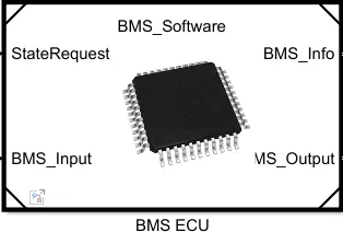
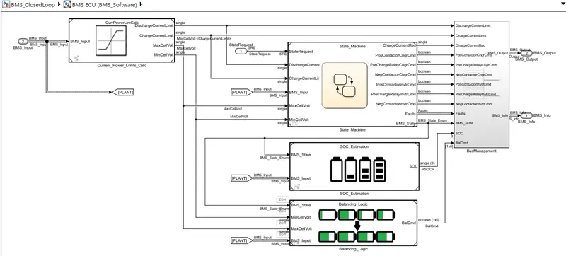
Opening BMS ECU block we will get subsystem shown below:
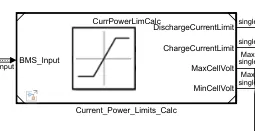
This block limis the current and power the block and its subsystem is shown below:
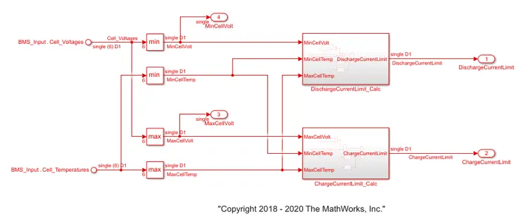
Here the cell voltage and the cell temperature is used to decide the maximum limit of discharge and charge current of the battery pack.
SOC help use to know acuratelly how many kilometer can be driven before the next recharging of the vehicle.
In battery system we dont measure SOC directly We measure some other parameters and depending on that we corelate the SOC of the battery.
There are 3methods to calculate SOC but the most common one is the coulomb counting method.
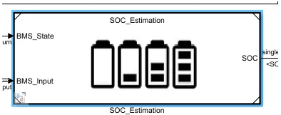
Below shown is the SOC estimation block:
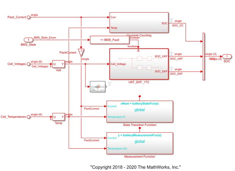
The inside subsystem of the above block is shown below:
Here is the coulomb counting block shown below:
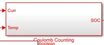
Inside this block we have some arrangement which takes current anddd temperature as input and gives SOC as output value.
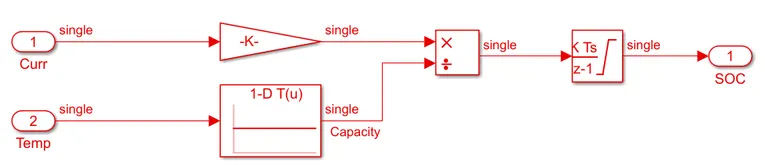
In coulomb counting method, the entering and leaving current of the cell are integrated to track the safe chargable time.
Here the two input signal are taken i.e. current and temperature. the current signal goes to the gain block and the temperature is given to current look up table. then signal are multiplied and divided as shown and the output is given to discrete time integrator to track the safe chargable time and the SOC estimation.
Coulomb counting method is simple and has low computational cost.