Week 7 State of charge estimation
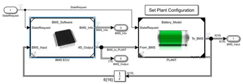
1) The BMS close loop harness dashboard block is shown below,
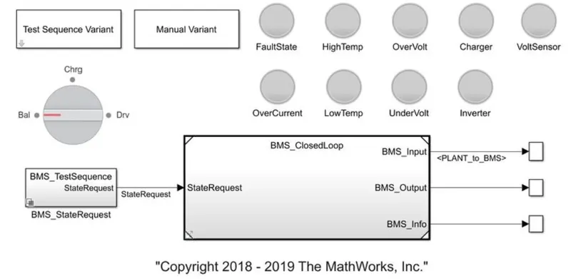
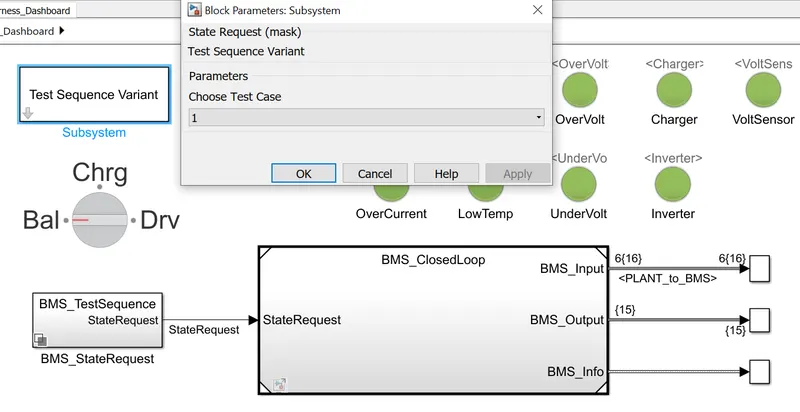
Double click the test sequence variant block to select the test case. Choose 1 and click ok.
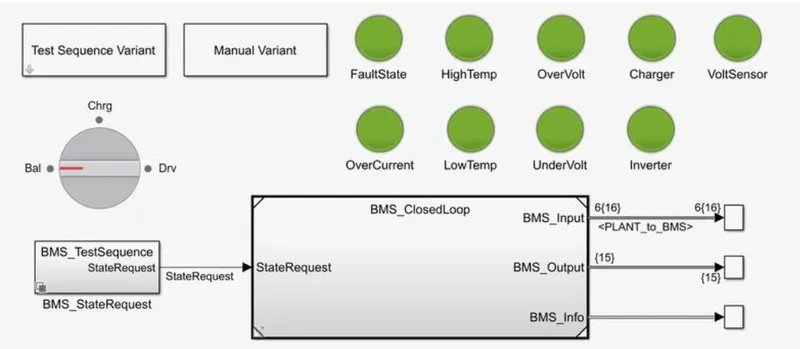
Simulated the model for 20,000 seconds as given. It shows no error and no fault. so, all the green light is indicated. The below block is shown,
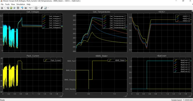
From the results, the vehicle starts in the driving state and charging upto 80%. The state of charge is reduces to around 30% and rises during driving. The temperature plot shows that, the temperature rises in charging and driving. The battery voltage rises till 4.2V in charging condition.The current is supplied to the vehicle during driving and it is shown in pack current plot.
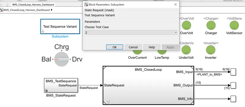
Choosing the case 2 test sequence variant,
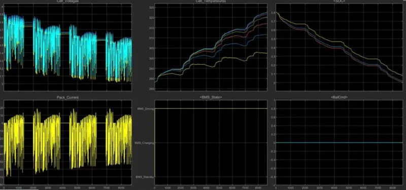
From the result, the battery discharge at 8692 seconds and the vehicle does not move. The charging condition was not achieved till 10,000 and the vehicle comes to standby condition. The SOC reduces to 0% in the driving condition and the charging state was not achieved.
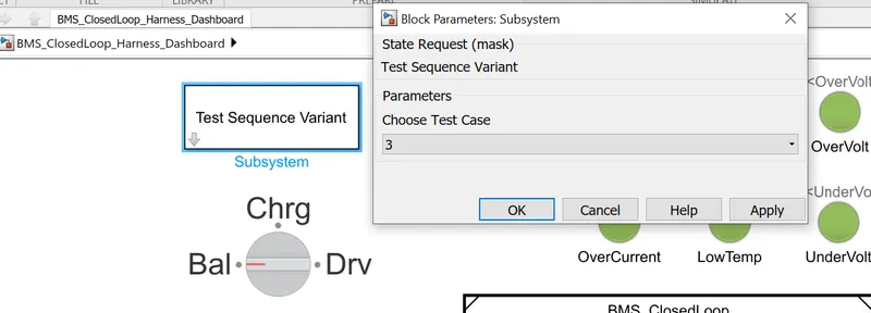
Choosing the case 3 test sequence variant,
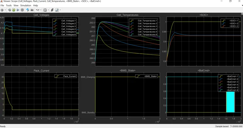
In the graph, the battery starts charging and the state of charge rises till 100% until 20,000 seconds. The SOC maintain continuously rise till the end of the simulation. The cell voltage is at 4.2V and reduces to 4.1V and maintain the range as constant. The battery pack current decreases due to regenerative braking while driving.
2) Coulomb counting:
It is the method of discharging current of a battery measurement and integrate the discharge current over time in order to determine SOC (State of Charge). The Coulomb counting method is determined by SOC(t), which is estimated from the discharge current I(t) and previous estimated state of charge value SOC(1-t). The SOC is calculated from the below equation,
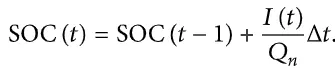
The SOC is based on inside and outside flow of current in the battery pack. The amount of charge in the battery pack is determined by,
- Rate of flow of current in and out of the battery
- Capacity of battery
To improve the method, the modified coulomb counting method is used. It uses the corrected current method to improve the accuracy of the estimation.
The modified coulomb counting method is determined by the SOC equation below,

Where, K are the constant value.

The Battery Management System (BMS) is used to monitor, protect and allow the user to use the battery pack in safe manner. This is the BMS cloop loop model as below,
This is the block inside BMS,
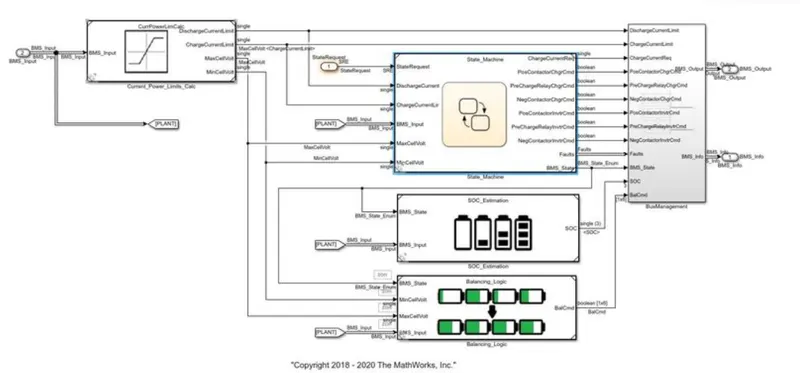
This is the SOC estimation block,
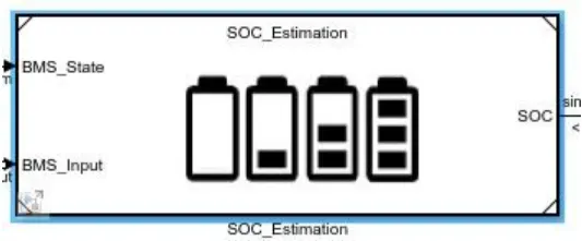
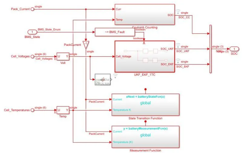
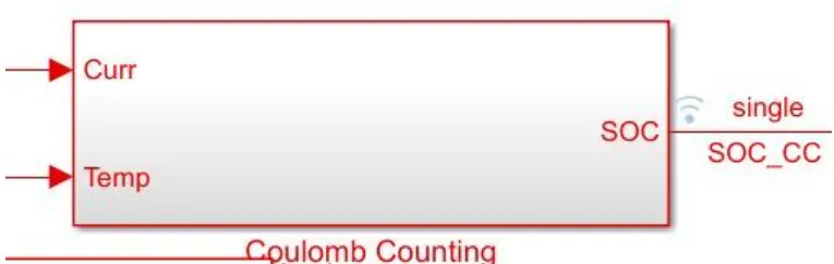
This is the sub-system of coulomb counting method. By double clicking this block, we get the below block of SOC estimation.
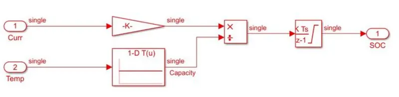
The Coulomb counting method is determined by the incoming and outgoing current are integrated to obtain the safe charging time. The two input signal is taken here, one is current signal and other is tempearture signal. The current input is given to the gain block and temperature given to look up table. The signal are multipled and divided as shown and given to discrete time integrator to track safe charge time and SOC is estimated. The coulomb counting method advantage is high accuracy and drawbacks are it increase in error rate with respect to time, temperature and life cycle.