Week 7 State of charge estimation
1.Simulate the 3 test cases from harness dashboard and write a detailed report on the results
BMS simulink block diagram:
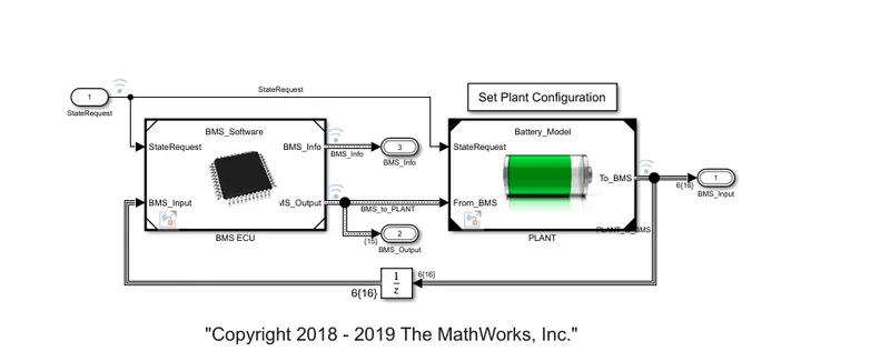
the basic simulink block model consist of two subsystems namely a shown these blocks are BMS ECU and PLANT unita as the sub units
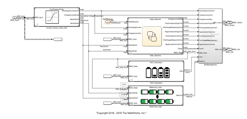
the above model is subsystems of the BMS CPU .this bolck mainly consists of the following subsystems
this ts a microchip which controls the statefunctions ,soc estimations and other balancing calculations by using the above blocksets represnted above
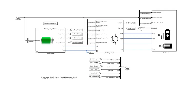
this is a subsystem model of the plant this consists of battery package unit ,precharge unit , charger and load units are connected to it
in battery pack there are two major configurations followed 1 modules which consist 6 cells on total it consists 16 modules on average it consists of 96 cells
1. open the BMS _closed harness _dashboard model files
2. model looks as follows
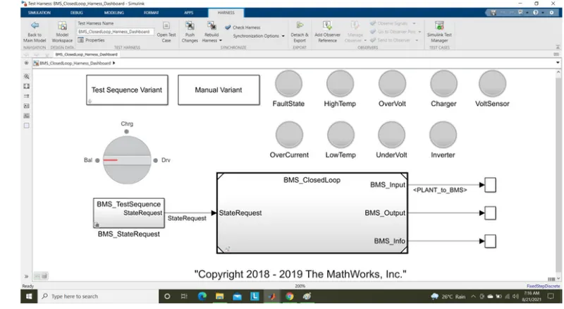
3.this model consists of
- test sequence varient (selector)
- manual varient(selector)
- BMS test sequence state request to provide state request
- lamps in order to indiacte the fault state ,high temperature ,over voltage ,over current ,charging ,voltage sensor operation ,inverter operation ,low voltage and under voltage
- rotating switch for manual varient changes
4. in scope results the soc of module ,module current ,individual cellvoltages ,individual cell temperatures , battery state , cell balancing states are seen as outputs
test cases:
case1:
1.select the test case 1 in the sequence varient box
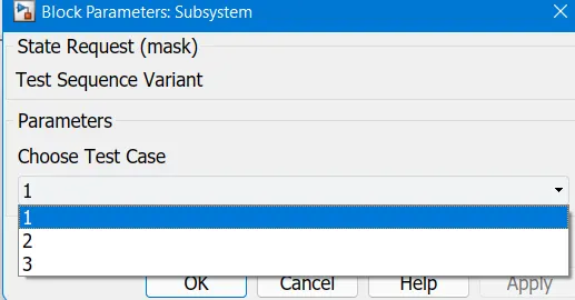
2.it represnts the changes in masked BMS_State request sub system as follows
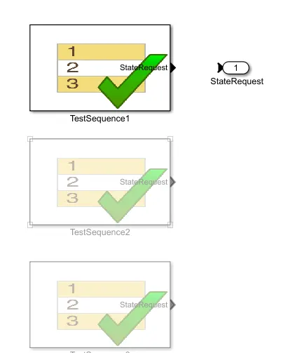
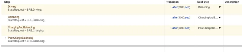
3. thses test cases contains the following operations
results:
run the simulation we get the following results
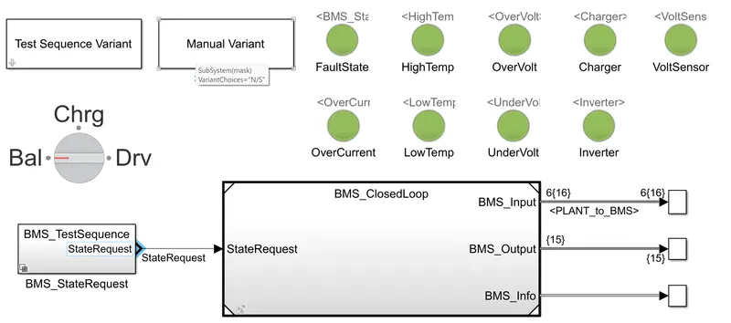
all the lamps are indicating th green colour which represnts all the operations performed are non fault
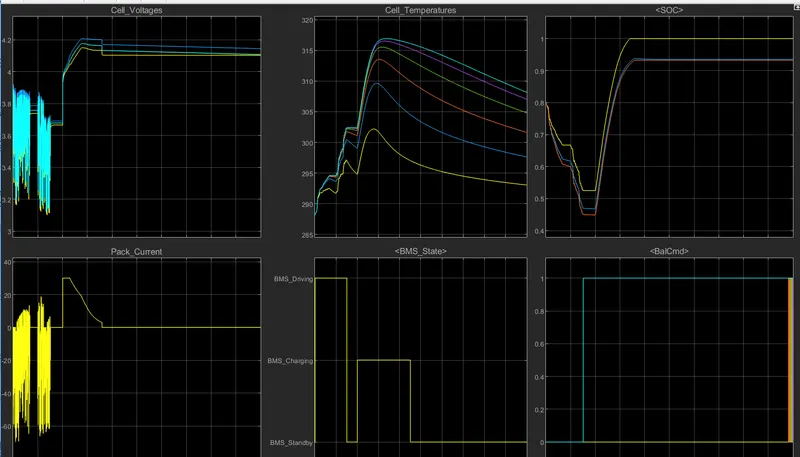
- cell voltages varied from 3.9v to 3.05v and charging is done at 3.7v to 4.2v as shown
- pack current is nearly 30A at 3.7v to 4.2 v and reduces from 30A to 2.6A
- at the end of 9000sec charging of battery takes place
- cell temperatures upto 3000 sec are 288k ,in between 3000sec to 4000sec is 302k module temperature increases upto 317sec
- soc from 80% to 45% upto 3000ses after charging it s maintained as 94%
- balancing of the cells is taking place after 3000sec
case2:
1.select the test case 2 in the sequence varient box
2.it represnts the changes in masked BMS_State request sub system as follows
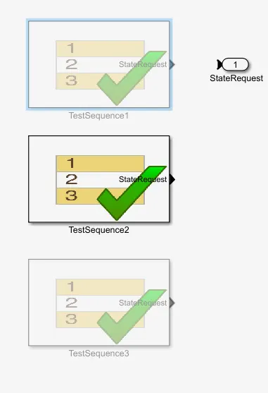
3. thses test cases contains the following operations
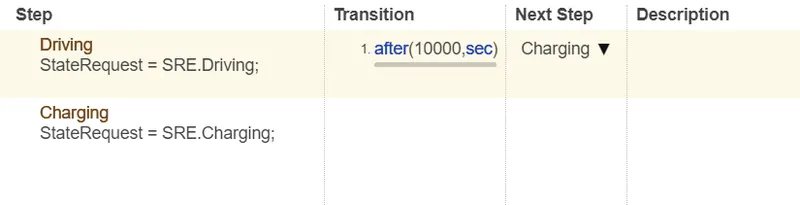
results:
run the simulation we get the following results
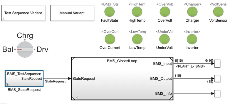
all the lamps are indicating th green colour which represnts all the operations performed are non fault
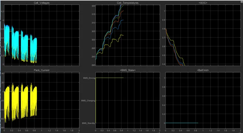
- cell voltages varied from 3.9v to 3.05v
- pack current is dicharged maximum up to 70A
- at the end of 9000sec charging of battery takes place
- cell temperatures upto 3000 sec are 288k ,in between 3000sec to 4000sec is 302k module temperature increases upto 322sec
- soc from 80% to 0% is drained as shown
- balancing of the cells is not performed
case3:
1.select the test case 2 in the sequence varient box
2.it represnts the changes in masked BMS_State request sub system as follows
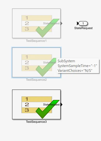
3. thses test cases contains the following operations

results:
run the simulation we get the following results
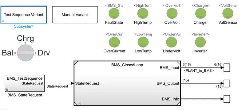
all the lamps are indicating th green colour which represnts all the operations performed are non fault
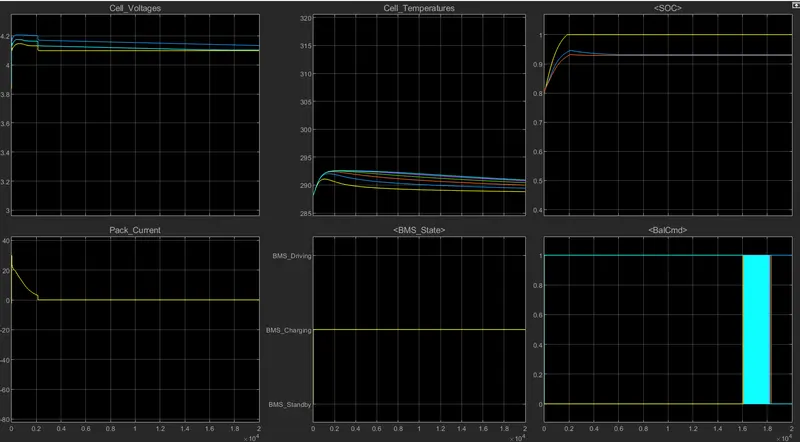
- cell voltages varied from 3.9v to 4.2v and stablised at 4.15v
- pack current is dicharged from 0 to 30A and reduced to 2.5v
- cell temperatures upto 3000 sec are 292.5k ,in between 3000sec to 4000sec is 292k module temperature decreases after gradually
- soc from 80%to 93% as shown it is in charging condition
- balancing of the cells 1 and cell2 is done remaining cells are tryed to balance at the end
2.What is coulomb counting? Refer to the above model and explain how BMS implements coulomb counting for SOC estimation ?
coulomb counting:
coulumb counting is an method which is used to measure the dicharging current of the battery and intergrates the dicharging current over time in order to estimate the SOC
governing equation:
`SOC (t) = SOC (t-1) + (I(t))/Q *dt`
SOC (t-1) represents the previous estimates state charge
I(t) is the dicharge current
by using the above parameters we can calculate the state of charge of the battery
modified coulomd counting:
this is the modified technique in order to calculate the state of charge there is a modifed dicharge function is used in order to calculate this
`Ic(t) =k2 *I(t)^2 +k1*I(t) +k0`
where k1,k2,k0 are the constants obtained by practical experimental techniques
`SOC (t) = SOC (t-1) + (Ic(t))/Q *dt`
soc estimation in BMS model:
1. open the BMS ECU model block
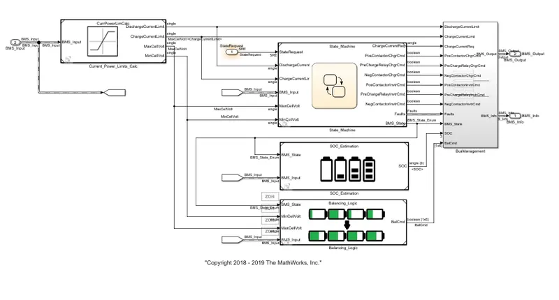
2.open soc estimation block set
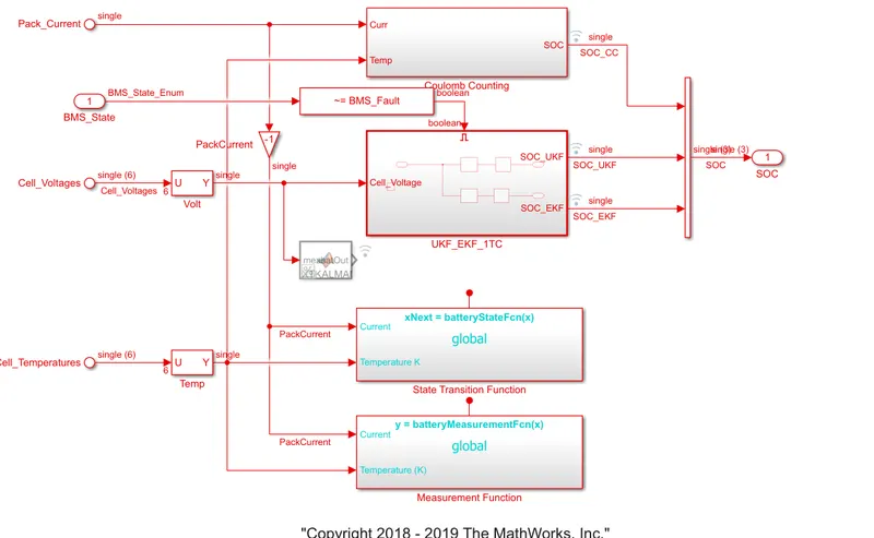
3.now open the coulomb counting block
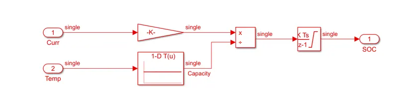
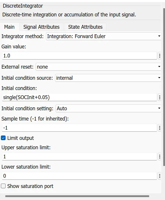
4. current from the input is obtained using the gain block with a element gain of 1/3600 multipled to obtain ucurrentcapacity
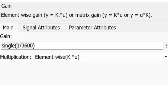
5.using look up tables along with the input temperature is provides with the signel
6.capscity signel is divided by the temperature signel as shown using divide block
7. the output signel is then integrated with the discrete integrator block with respect to time which gices the state of charge SOC