State of charge estimation
Battery management systems (BMS) are electronic control circuits that monitor and regulate the charging and discharge of batteries. The battery characteristics to be monitored include the detection of battery type, voltages, temperature, capacity, state of charge, power consumption, remaining operating time, charging cycles, and some more characteristics.
The task of battery management systems is to ensure the optimal use of the residual energy present in a battery. In order to avoid loading the batteries, BMS systems protect the batteries from deep discharge, from over-voltage, which are the result of extreme fast charge and extreme high discharge current. In the case of multi-cell batteries, the battery management system also provides for cell balancing function, to manage that different battery cells have the same charging and discharging requirements.
The following functions are performed by BMS for its optimal utilisation:
Cell Protection:
Protecting the battery from out of tolerance operating conditions is fundamental to all BMS applications. In practice, the BMS must provide full cell protection to cover almost any eventuality. Operating a battery outside of its specified design limits will inevitably lead to the failure of the battery. Apart from the inconvenience, the cost of replacing the battery can be prohibitive. This is particularly true for high voltage and high power automotive batteries which must operate in different environments and which at the same time are subject to abuse by the user.
Charge control:
This is an essential feature of BMS. More batteries are damaged by inappropriate charging than by any other cause.
Demand Management:
While not directly related to the operation of the battery itself, demand management refers to the application in which the battery is used. Its objective is to minimise the current drain on the battery by designing power-saving techniques into the applications circuitry and thus prolong the time between battery charges.
SOC Determination:
Many applications require a knowledge of the State of Charge (SOC) of the battery or of the individual cells in the battery chain. This may simply be for providing the user with an indication of the capacity left in the battery, or it could be needed in a control circuit to ensure optimum control of the charging process.
SOH Determination:
The State of Health (SOH) is a measure of a battery's capability to deliver its specified output. This is vital for assessing the readiness of emergency power equipment and is an indicator of whether maintenance actions are needed.
Cell Balancing:
In multi-cell battery chains, small differences between cells due to production tolerances or operating conditions tend to be magnified with each charge/discharge cycle. Weaker cells become overstressed during charging causing them to become even weaker until they eventually fail to cause premature failure of the battery. Cell balancing is a way of compensating for weaker cells by equalising the charge on all the cells in the chain and thus extending battery life.
History - (Log Book Function):
Monitoring and storing the battery's history is another possible function of the BMS. This is needed in order to estimate the State of Health of the battery, but also to determine whether it has been subject to abuse. Parameters such as the number of cycles, maximum and minimum voltages and temperatures and maximum charging and discharging currents can be recorded for subsequent evaluation. This can be an important tool in assessing warranty claims.
Authentication and Identification:
The BMS also allows the possibility to record information about the cell such as the manufacturer's type designation and the cell chemistry which can facilitate automatic testing and the batch or serial number and the date of manufacture which enables traceability in case of cell failures.
Communications:
Most BMS systems incorporate some form of communication between the battery and the charger or test equipment. Some have links to other systems interfacing with the battery for monitoring its condition or its history. Communications interfaces are also needed to allow the user access to the battery for modifying the BMS control parameters or for diagnostics and tests.
Working of BMS model:
The following Simulink model is used to determine the performance of a BMS under various conditions:
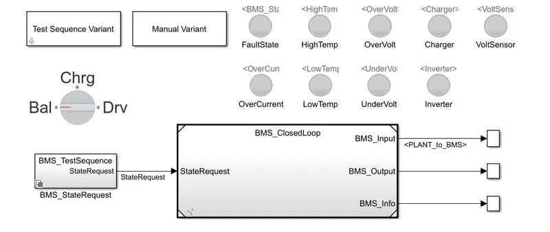
The highest level of the model consists of indicator lights for fault analysis at various lower stages and the parameters like voltage and temperature. The test sequence variant can be chosen between the 3 existing variants and a manual variant. The rotary switch can be used to switch between different modes in real-time when the model is running under the manual variant. The three test sequence variants have the following state configurations:
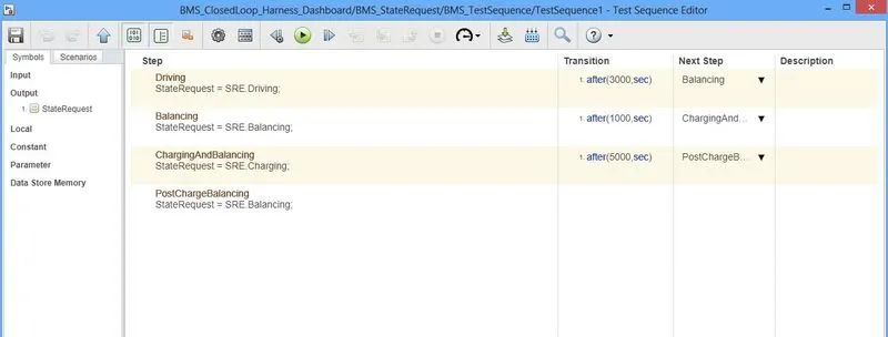
Test 1 has a driving mode for 3000 seconds followed by the balancing mode for 1000 seconds. After balancing, charging of the battery takes place for 5000 seconds followed by post charge balancing for the rest of the time period (20000 seconds).
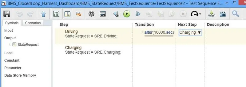
Test 2 is quite similar to the long run where the system is under driving state for about 10000 seconds followed by charging state.
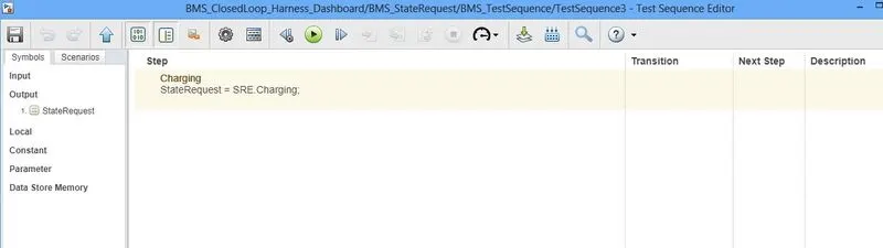
Here, the time step for each operating condition and the next operation to be followed after a certain period of time is provided for every test variant. For the provided period of time, the state request signal in the test variant is provided to the BMS block. BMS block has a subsystem inside it and the model inside the BMS is as follows:
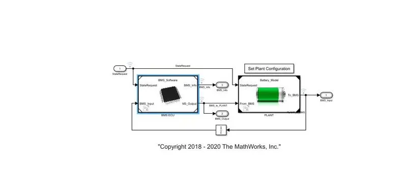
The closed-loop BMS has the following subsystems namely ECU (Electronic Control Unit) and plant. The ECU subsystem model is as follows:
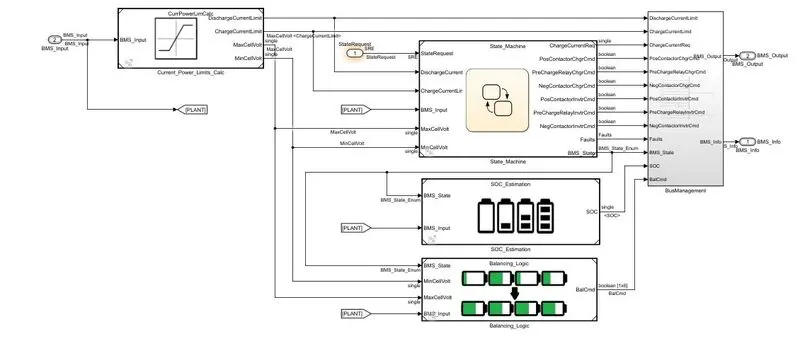
The ECU model gets the inputs from the test variant selector and battery. These inputs are passed through the power limits calculator before providing to the state machine, SOC calculator and balancing logic. The state machine checks the voltages, currents, test state, temperature and checks out for faults before sending those signals to the bus management. The SOC estimation of the battery is carried out by following three methods. These methods are as follows:
1. Coulomb Counting
2. Unscented Kalman Filter
3. Extended Kalman filter
Coulomb Counting:
The Coulomb counting method measures the discharge current of a battery and integrates the discharge current over time in order to estimate SOC. Coulomb counting method is done to estimate the, which is estimated from the discharging current [I(t)], and previously estimated SOC values [SOC(t-1)]. SOC is calculated by the following equation:
`SOC(t) = SOC(t-1)+(I(t))/(Q_n)*trianglet`
But there are several factors that affect the accuracy of the Coulomb counting method including temperature, battery history, discharge current, and cycle life.
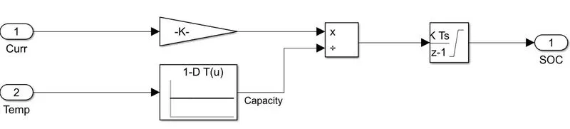
The above Simulink model represents the coulomb counting method to determine the SOC of a battery where the time is converted in terms of hours and sent to an integrator and the resultant signal is passed to the BMS as SOC of the battery pack.
UKF Unscented Kalman Filter:
The Unscented Kalman Filter (UKF) is a novel development in the field. The idea is to produce several sampling points (Sigma points) around the current state estimate based on its covariance. Then, propagating these points through the nonlinear map to get a more accurate estimation of the mean and covariance of the mapping results.
EKF Extended Kalman Filter:
the extended Kalman filter (EKF) is the nonlinear version of the Kalman filter which linearizes about an estimate of the current mean and covariance.
Battery balancing logic:
Battery balancing works when the battery balancing state is activated. It checks the voltages of every single battery and based on the difference in voltages between the batteries, the battery balancing takes place.
All these signals are provided to the BMS output and battery plant to understand the performance of the BMS under different test conditions using plots.
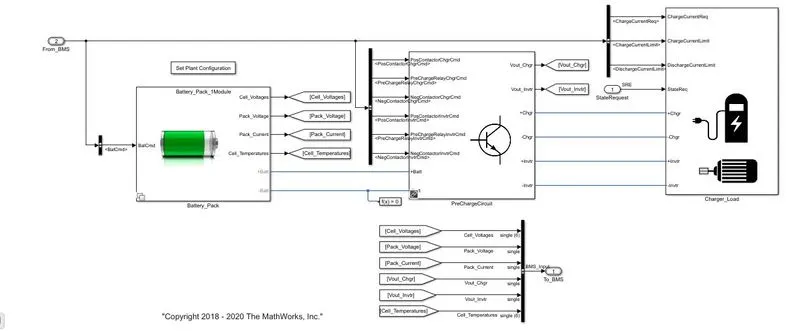
The Battery subsystem consists of the battery module configuration, precharge circuit, charge and load models. There are two options while choosing the battery pack, 1 module and 16 module where each module has 6 similar batteries. These voltages are sent to the BMS's ECU to determine the initial SOC of the battery. The BMS signals are provided to the charging and load modules where the load is provided to the system based on the driving cycles for a period of time mentioned by the test variant. The charging circuit charges the batteries based on the current required and the state requested by the test variant and is provided to the battery through the pre-charging circuit.
Results for test variants:
Test 1:
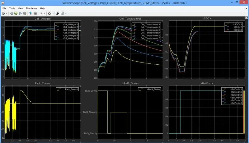 The voltage graph has variation in voltage as the battery gets stressed by the drive cycle conditions till its state changed to the balancing mode(after 3000 seconds). At this stage, we get a voltage value of ~3.7V. At 4000 seconds, there is a sudden spike in the voltage as the charging phase is coming into play and attains a peak voltage of 4.2V and gradually gets balanced to 4.1V at 7000 seconds. At 8000 seconds, the post-charge balancing phase takes place.
The current graph has the same variation when the battery pack is at the driving phase. At the balancing phase, the current becomes 0A followed by a peak current of 30A while the battery pack gets charged. The current gradually decreases to 0A at the post-charge balancing phase.
The cell temperature graph shows the temperature rise in batteries at different phases. There is a higher change in temperature during the charge phase and every individual battery exhibit a higher temperature curve than the previous one due to their position and ventilation.
The BMS state graph shows the phase change of BMS over the time frame of 20000 seconds.
SOC graph shows the decline of battery charge during the driving phase and increases during the charge phase. The SOC becomes 100% at 7000 seconds gets balanced leading to constant voltage and 0A current. The yellow curve represents coulomb counting while the blue and orange lines represent the UKF and EKF method of determining SOC. As there is little space for error rectification in coulomb counting, the SOC % data provided by the coulomb counting is not accurate when compared to UKF and EKF.
The balancing command graph shows the state of the balancing command in terms of 0 and 1. 0 refers to off and 1 refers to on state. In this test variant, the balance command is switched on from 3000 seconds and thus it gives the result as 1 for the rest of the time period.
Test 2:
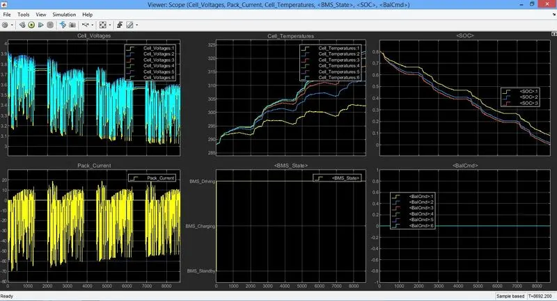
In this case, the whole system is under the driving phase for the period of 10000 seconds before switching to the charging phase. Due to this the voltage and current gets fluctuated till the battery gets completely drained or the charging phase is attained. The voltage and current fluctuation are based on the drive cycle provided to the system.
The rise in temperature is caused by the continuous loading of the battery during the driving phase thus the BMS state remains at driving over the period of time.
SOC of the battery gradually becomes 0 at ~8500 seconds. As the battery pack reached 0 SOC% before 10000 seconds, the charging phase was not activated.
In this variant, balancing state was not mentioned thus the BMS bal command graph as 0 over the period of time.
Test 3:
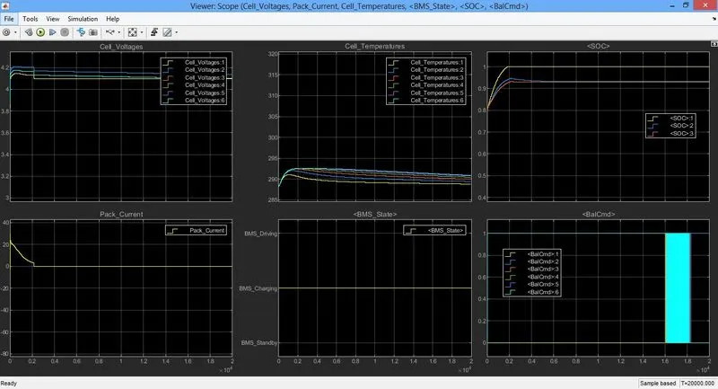
The voltage gradually increases till the SOC % becomes 100 as this test variant has the charging phase for the whole time span and reaches 4.1V while the current reaches 0A.
The temperature of the batteries increases till the batteries get completely charged (~2100 seconds) and gradually decreases to almost ambient temperature through its time span.
As this is a completely charging variant, the BMS state indicates a charging state throughout the time span.
The SOC of the battery increases from its initial 80% to 100% by 2100 seconds and remains constant without getting overcharged.
The bal command is shifted from 0 to 1 to maintain the charge level. The fluctuation between 0 and 1 (at 16000 to 18000 seconds) is to maintain 100% when the battery gets discharged.