Doorbell and Thermistor
Aim:
- To make a Simulink model of a doorbell using solenoid block.
- To make a Simulink model using a thermistor to sense the temperature of the heater and to switch on or off the fan.
Objectives:
- To create a Simulink model of a doorbell using a solenoid block with the following conditions:
- The switch is closed for 2 seconds and then released.
- To observe the physical movement of the plunger.
- To create a Simulink model using a thermistor to sense the temperature of the heater and to switch on or off the fan with the following conditions:
- Temperature source: 20 °C from 0 to 10 seconds, 27 °C from 10 to 30 seconds, 23 °C from 30 to 50 seconds.
- Fan conditions: ON if the temperature above 25 °C, OFF otherwise
Theory:
Solenoid:
A solenoid is a type of electromagnet which is used to generate a controlled magnetic field through a coil wound into a tightly packed helix. The coil can be arranged to produce a uniform magnetic field in a volume of space when an electric current is passed through it.
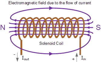
In this project, the solenoid is used as an electromagnet to induce the attractive and repulsive motion of the plunger when the current is passed through the coil. When the current is passed through the electromagnet, a magnetic field is produced that attracts the plunger which in turn hits the bell. When there is no current provided to the electromagnet, the plunger retracts back to its original position.
Thermistor:
A thermistor is a type of resistor whose resistance is dependent on temperature.They are classified into two types:
- NTC (negative temperature coefficient) in which the resistance decreases as temperature increases. It is most commonly used as a temperature sensor.
- PTC (positive temperature coefficient) in which the resistance increases with rising temperature. It is most commonly used to protect against overcurrent conditions as fuses.
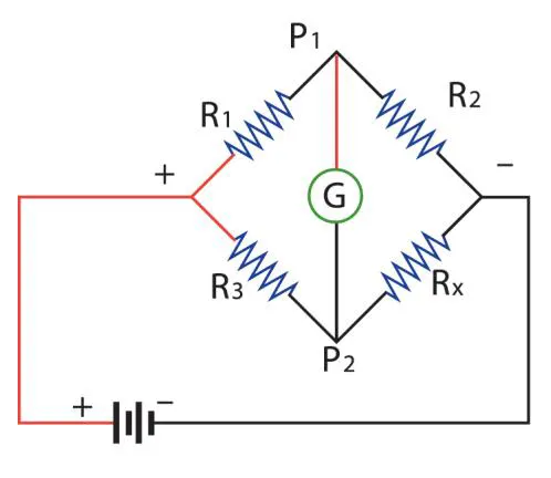
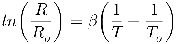
Where R0 is the resistance at a reference temperature, T0, while ß is a constant, characteristic of the material, T0, the reference temperature, is generally taken as 298 °K (25 °C). Where R is the measured temperature. The resistance is measured in terms of voltage or current changes.
Simulink model:
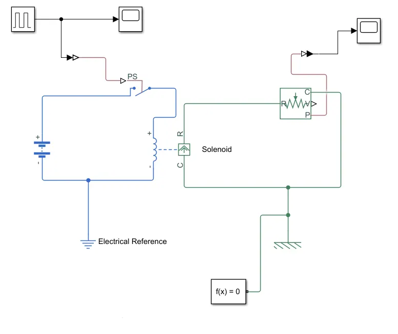
DOORBELL MODEL:
The input signal is sent from the pulse generator. The input Simulink signal is converted into a physical signal using Simulink to ps converter. It is provided as a condition or control to the switch that connects the solenoid. It provides the required 2-second press for the switch. A battery is connected to the electrical reference and connected to the solenoid. The other half of the solenoid is connected to the mechanical ports and connections are made for creating the pulling force. A mechanical reference and a solver configuration are provided. The translational motion sensor is used to locate the position of the plunger with respect to the reference position. The resultant position is displayed using the scope. In order to convert the physical signal to the Simulink signal, the Simulink converter is used and the resultant points are plotted. The amplitude, pulse width and time period for the pulse generator are provided and the rest of the parameters are assumed. The damping, spring constant influence the results provided by the motion sensor.
THERMISTOR MODEL:
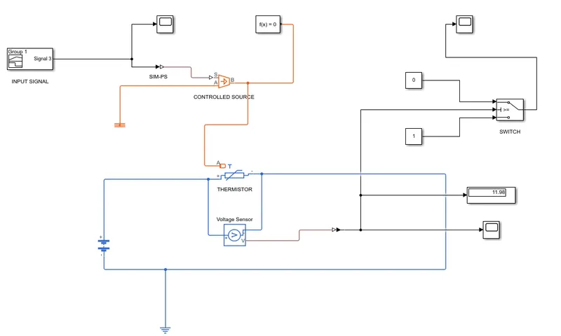
The input parameters are provided to the signal builder based on the required conditions. It is then converted into the physical signal using Simulink to ps converter. The physical signal is provided to the controlled temperature source. A solver configuration is added to the output signal port of the temperature source and it is provided to the thermistor. Thermal and electrical references are provided to the model. The battery is provided as a power source to the thermistor. The resistance change due to the influence of the temperature is measured in terms of voltage (in this model) and the obtained physical value (voltage) is converted to the Simulink signal. The voltage is plotted and the latest value is displayed. Based on the plot obtained, the minimum value(voltage) is found from the plot and based on that, the threshold value is set to the switch. Constants 1 and 0 are set to ON and OFF position for the fan. When the voltage is low, the temperature obtained is high, so the fans are switched ON. when the temperature is greater than the threshold value, the fans are switched off. The resultant is boolean values i.e ON and OFF are plotted.
Result:
Doorbell input:
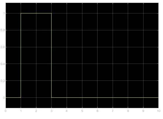 X-axis = Time. Y-axis = Signal
Plunger movement:
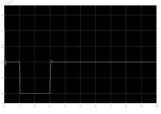 X-axis = Time. Y-axis = Plunger position
Thermistor input signal:
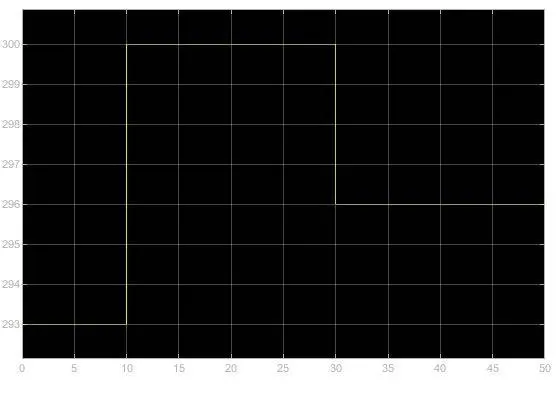 X-axis = Time. Y-axis = Temperature
Output voltage signal:
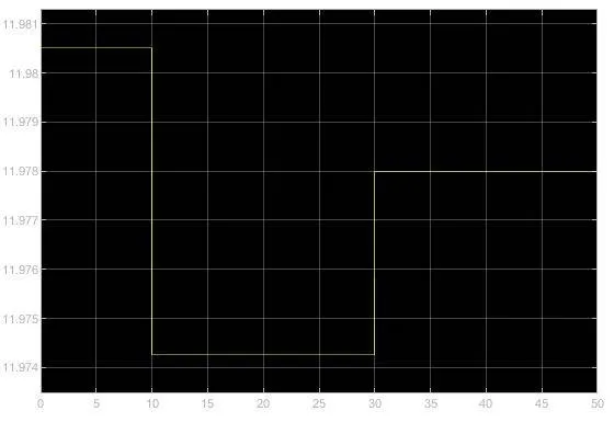 X-axis = Time. Y-axis = Voltage
Switch signal for the fan:
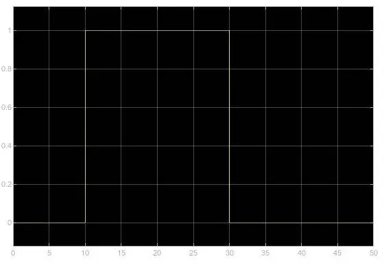 X-axis = Time. Y-axis = Switch signal
Inference:
- The position of the plunger depends on factors like the electrical input to the solenoid and the electro-mechanical properties of the solenoid.
- The thermistor depends on the input signal source i.e the temperature source.
- The temperature can be measured in terms of voltage or current.
- Adding resistors(in series) can influence the results obtained.
References:
https://en.wikipedia.org/wiki/Solenoid