Week 7 State of charge estimation
1. Question(1):-
Simulate the 3 test cases from harness dashboard and write a detailed report on the results :-
Harness dashboard in MATLAB is as follows :-
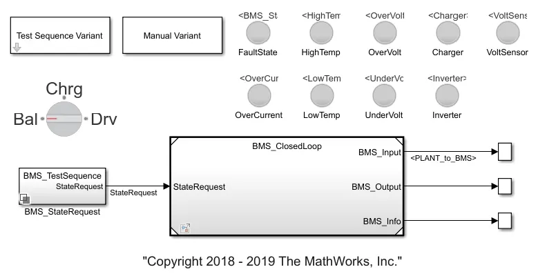
It consists of some lamps as indicator to actually tells the status of the system like :-
- Fault state
- High temperature,Low temperature
- over voltage ,under voltage.
- Over current.
- Charger connected ,Inverter connected.
There are 3 test cases in which each test cases has some mode like driving,charging,standby.
So, this test cases are selected with help of test sequence variant block then in BMS state request that state request corresponds to selected test cases is activated and given to BMS system.
Test case 1 :-
It includes state like driving-balancing-charging-post balancing .
First test sequence are selected here in this case it is selected as 1.
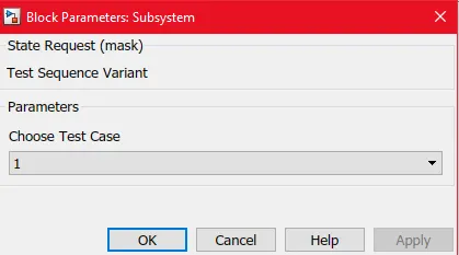
After that BMS state status selected as 1.
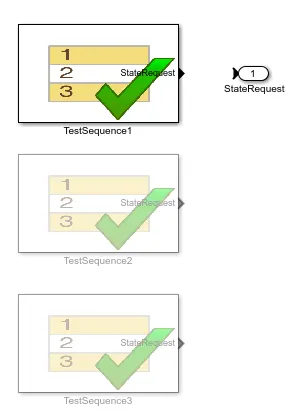
After that what is the state followed in this test case are shown:-
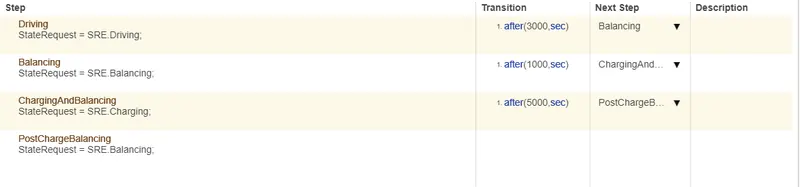
In this it is shown that first driving is done after 3000 seconds balancing then after 1000 seconds charging and at last after 5000 seconds post balancing is done.
So, depending on this state how is the cell voltage,temperature ,SOC graph,etc are monitoured which is shown below :-
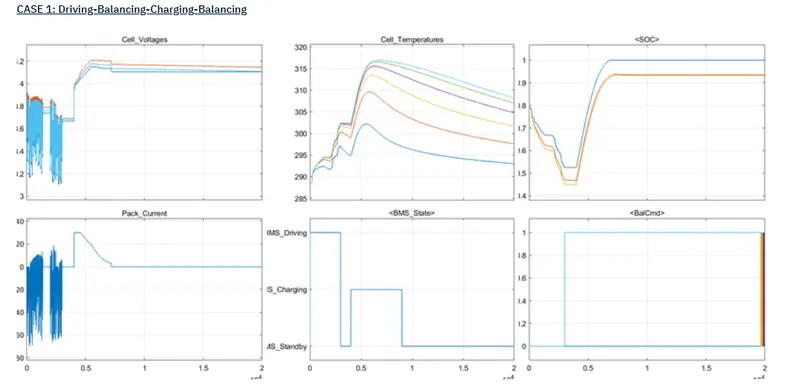
Here BMS state depends on time mentioned above is executed.
During driving mode , cell voltage decreasing and slightly increase in case of regenerative braking,pack current are fluctuating ,cell temperature continiously increasing,SOC decreasing and balance command is at zero.
After that standby mode in which cell balancing is done voltage across each cell become equal,pack current is at 0,balance command apply and SOC graph is at some constant value.
After that charging is done in which cell voltage increase,soc increases
After that ,post balancing is done again SOC is stable ,voltage equilize,pack current 0 and as battery pack is not in operation so cell temeprature reduces.
Test case 2:-
It includes state like driving-charging,high temperature fault.
First test sequence are selected here in this case it is selected as 2.
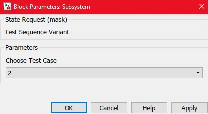
After that BMS state status selected as 2.
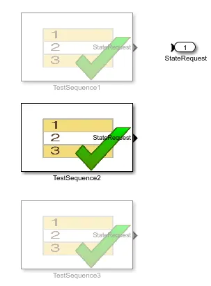
After that what is the state followed in this test case are shown:-
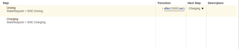
Here first driving then after 10000 seconds charging is done.
So, depending on this state how is the cell voltage,temperature ,SOC graph,etc are monitoured which is shown below :-
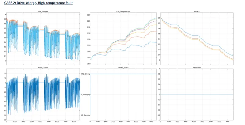
During driving mode , cell voltage decreasing and slightly increase in case of regenerative braking,pack current are fluctuating ,cell temperature continiously increasing,SOC decreasing and balance command is at zero.
Test case 3 :-
It includes state like charging.
First test sequence are selected here in this case it is selected as 3.

After that BMS state status selected as 3.
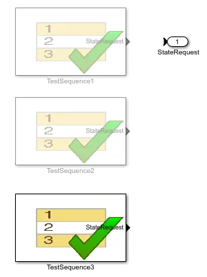
After that what is the state followed in this test case are shown:-

Here only charging is done.
So, depending on this state how is the cell voltage,temperature ,SOC graph,etc are monitoured which is shown below :-
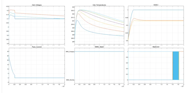
Here bms is in charging state ,first cell voltage increases ,temperature also increases,SOC graph increases to 1 and saturate.
2. Question(2):-
a. What is coulomb counting?
There are different methods for estimation of state of charge (SOC),out of them coulomb counting is one method.
It is very accurate but dependent on accurate SOH and precision of current measurement.
Coulomb counting requires correct starting point (intial SOC),the only time that the correct SOC is known is when the battery is fully charged or discharged.
Coulomb count between two instant will indeed be a good measure of energy added or removed from a battery but will represent SOC only to thr extent that intial SOC was good.
Change in SOC (delta SOC)= Charge pumped in or out of battery/(Intial capacity *State of health(SOH)).
Where charge pumped in and out is coulomb count*electron charge or integration of current over time . If computed charge is "In" the delta SOC is positive ,else it is negative .
SOC(new)=SOC(old)+delta SOC.
Some disadvantages of coulomb counting method :-
- Estimation of intial SOC is very critical, if some error included in this calculation then whole calculation will contains an error .
- In operation of the vehicle,battery is fully charged or discharged never happens.
- Also, such methods require that the current measurement is perfect, but no current sensor is immune from noise, component-to-component variations and other effects. Therefore small errors always exist in every measurement and these errors may cause the estimates to wander away from the true value.
- Thus, Coulomb counting is not a preferred method for SoC estimation when a battery must be operated for long time without full charge or discharge.
- If the initial condition is known and the battery is operated for a relatively short period of time, then this method does provide a reliable measurement.
b. Refer to the above model and explain how BMS implements coulomb counting for SOC estimation ?
MATLAB model of battery pack along with battery management system (BMS) is as follows:-
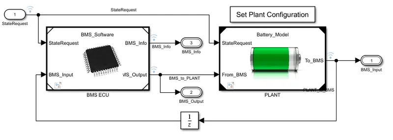
There is a "plant" system in which battery modules are present along with precharge circuit and charger and inverter.
Charger are used to charge the battery module and Inverter are used to convert DC into AC which is given to load.
There is a unit called BMS which monitor the cell voltage,current,temperature ,calculation of SOC ,etc.
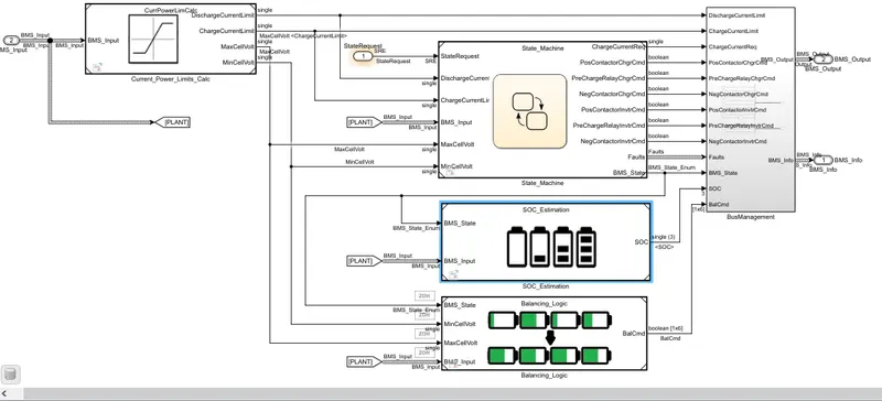
Inside BMS there are three subsystem :-
- State Machine.
- SOC estimation.
- Battery balancing.
Inputs to SOC estimation block are BMS state input and plant input.
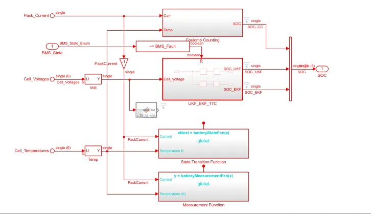
These are types of methods for SOC estimation such as coulomb counting,UKF .
In Coulomb counting method as discussed above ,two inputs are given one is total pack current and other one is temperature.
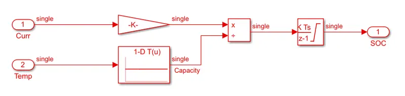
This is the model taht is implimented to calculate the soc using coulomb counting.
It includes some block such as :-
- Gain
- Look up table(Temperature v/s capacity)
- Division
- Discrete integrator
Steps for state of charge estimation using coulomb counting:-
1. The total pack current from the battery module which is taken from BMS is given to gain block.
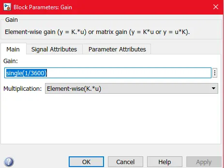
"single" is set as variable for pack current. single*(1/3600) is the gain.
2. The sensed temperature from BMS is given to look up table which helps that at what temperature what is the capacity of battery.
So battery capacity are calculated at respective temperature.
3. Then current and capacity are given to divisor blockand we get:-
pack current/(3600*capacity).
4. Then using integrator with help of coulomb counting ,integrating previous values of current over period of time gives total charge estimation.
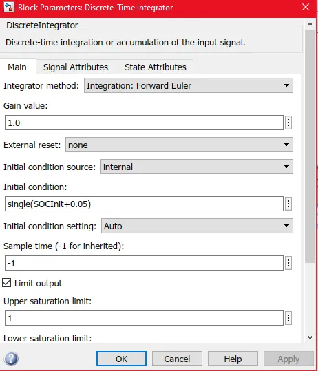
Forward euler's are used as an method for integration and as it is discrete integrator sample time of -1 is used.
5. So in this way the final SOC are estimated using coulomb counting.