Week - 4
A.
1. Title :-
Implement control logic of a “washing machine” using Stateflow.
2. Introduction :-
Using stateflow ,control logic of washing machine with some condition's are as follows :-
- If the power supply is available, the system gets activated
- If the Water supply is not available, stop the process & indicate through LED
- Soaking time should be 200s followed by Washing time of 100s.
- Then rinsing happens for next 20s & dryer runs for 50s.
The block's used in this simulation model are:-
1. Chart .
2. Constant.
3. Display.
4. Lamp.
3. Workdone :-
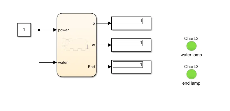
Stateflow model of above problem statement are as follow's :-
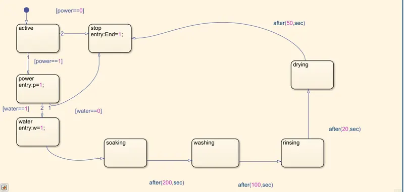
- In this model input are power supply , water supply and output are p,w and end.
- In stateflow model inputs are always defined on arrow and output are defined in state block.
- If,we see the stateflow model if power and water are 1 then the process continues that is soaking ,washing,rinsing,drying and end.
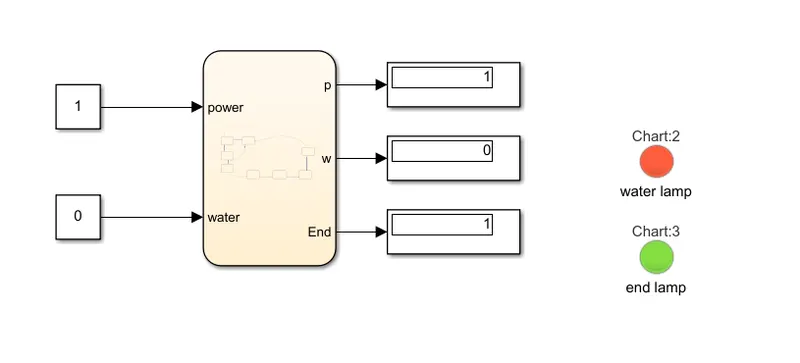
- If, power =1 and water=0 then process directly comes to an end.
- And if power=0 then obviously process comes to an end , without power supply how can washing machine be run.
- Input's as power and water supply are represented as constant block.
- Outputs are displayed in two way's that is with help display and lamp.
- Two lamp's are used one to detect water supply and one to detect either to detect the process is finished or not.
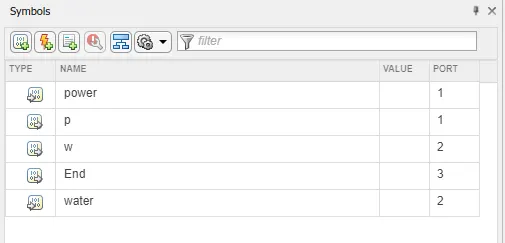
- whatever the input and output are defined in stateflow model ,it has to be first defined in symbol pane and select it accordingly as input and output port.
4. Result :-
a) If power supply=1 and water supply=1:
b)If power supply=1 and water supply=0:
 5. Conclusion :-
Comprehensive simulation is carried out in MATLAB/SIMULINK and result are analyse thoroughly.
B.
1. Title :-
Implement Simulink chart for the “Gear shift” logic.
2. Introduction :-
Simulink chart for the “Gear shift” logic with some conditions are as follow's :-
Speed Range(kmph) Gear
0 to 15 1
16 to 25 2
26 to 40 3
41 to 60 4
Above 61 5
The block's used in this simulation model are:-
1. Chart .
2. Constant.
3. Display.
3. Workdone :-
Stateflow model of above problem statement are as follow's:-
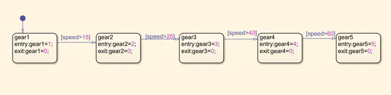
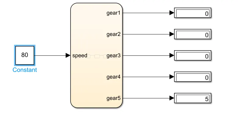
- In this stateflow model input is speed and output are gear's
- Depending on speed respective gear is alloted.
- All input and output are defined in symbol pane and it is shown as under :-
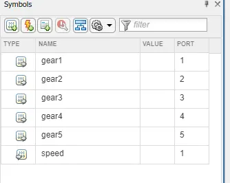
- Input is represented by constant block and output is displayed with the help of display block.
4. Result :-
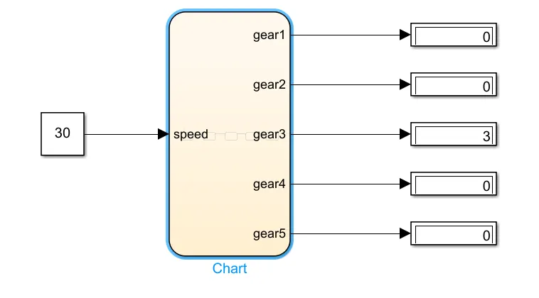
a) For speed of 30 kmph ,respective gear number is 3.
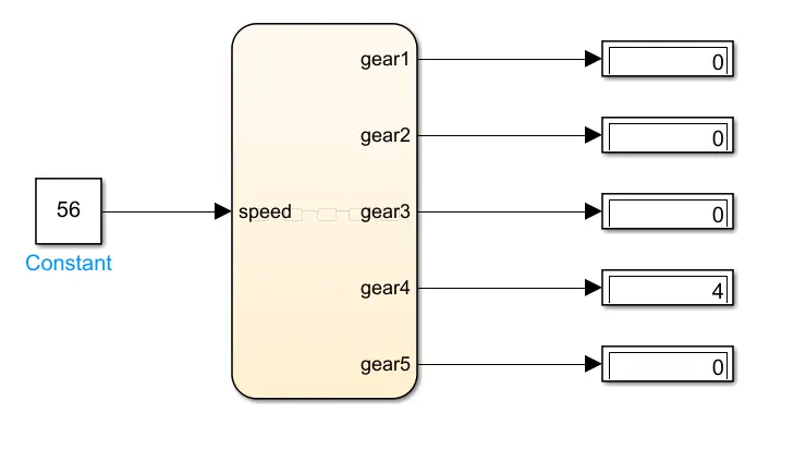
b) For speed of 56 kmph ,respective gear number is 4.
c)For speed of 80 kmph ,respective gear number is 5.
5. Result :-
Comprehensive simulation is carried out in MATLAB/SIMULINK and result are analyse thoroughly.