Week-6 Challenge: EV Drivetrain
1. Which types of power converter circuits are employed in electric and hybrid electric vehicle?
Hybrid electric vehicle (HEV) :-
- In HEV it contains more than one source.
- But at least one of the source can supply electrical power for propulsion.
- Based on the combination of sources there are different types of HEV,but most commonly used is internal combustion engine (ICE) along with electrical motor.
Electric vehicle (EV) :-
- In this vehicle is run through pure electrically.
- Its only contain electric motor for propulsion that is single source.
Power converter circuits used in EV and HEV are follows :-
a. Rectifier(charger) :-
- It convert AC supply to DC supply required for the battery to charge.
- Battery output voltage can vary from 400v to 800v .
- Battery may be charged by the on board charger (AC/DC) using a regular outlet or larger fast charger, external to the vehicle.
b. Inverter :-
- Inverter circuit is used to convert the DC supply to AC supply which is required by AC motor to run.
- The inverter is a bi-directional converter that accepts the high voltage from the battery and converts it into AC supply voltage suitable for the traction.
- During the deceleration that is regenerative breaking period the motor absorbs the torque and provide the AC voltage to the inverter.
- The inverter controls the amount of the energy generated by the motor and consequently the intensity of the braking. The harvested energy is
applied back to the battery as a charge.
c. Chopper :-
- Chopper is the circuit which convert DC supply at one voltage level to DC supply at other voltage level
- It is also called as DC to DC converter.
- The chopper circuit are of three type :-
- Boost chopper(step up )
- Buck chopper (step down)
- Buck-Boost chopper.
- Mainly in vehicle the step down chopper is used as it is used by vehicle auxillaries which can operate on low voltage DC supply.
- The auxillaries are headlight,power (streering,brake and window),air conditioning,music system ,etc.
2. An Electric Vehicle's powertrain with 72V battery pack in shown below:-
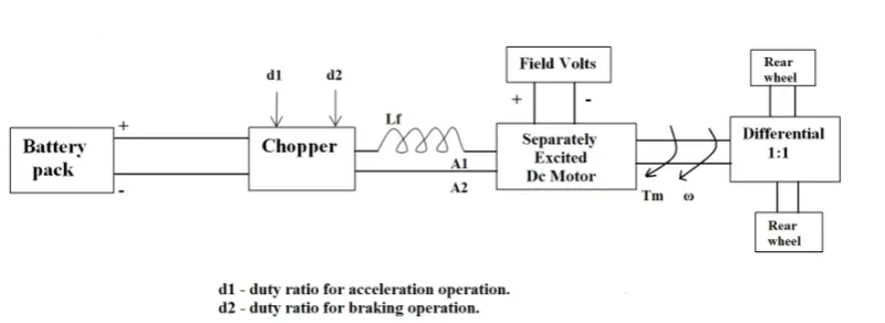
- Rated armature voltage = 72v
- Rated armature current (Ia) = 400A
- ra = 0.5 ohms
- kϕ = 0.7 volt-second
The vehicle speed torque characteristic of is :-
T = 24.7+(0.0051)*ω^2.....equation 1
The DC motor speed -torque characteristics is given by:-
(kϕ)*V/ra - (〖(kϕ)〗^2*ω)/ra....equation 2
As steady state speed is calculated at duty cycle of 70%
Therefore average voltage applied to dc motor supply terminal is V=0.7*72 = 50.4volt
Putting all the values in equation 2 we get:-
(0.7)*50.4/0.5-〖(0.7)〗^2*ω/0.5
T=70.56-0.98*ω.....equation 3
plotting equation 1 and3 we get :-
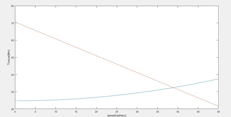
- In this plot torque in Nm and speed in rad/sec.
- The plot is in red colour is of DC motor characteristics and plot is in blue is of vehicle characteristics.
- The intersection of both the plot is the steady state speed point and that has to be calculated.
- The matlab script for plotting above plot are as follows :-
clc speed =linspace(0,50,10); torque = 24.7+((0.0051)*speed.*speed); %torque-speed characteristic of vehicle speed1=linspace(0,50,10); torque1=70.56-(0.98*speed1); %torque -speed characteristic of DC motor plot(speed,torque); hold on plot(speed1,torque1); xlabel('speed(rad/sec)'); ylabel('Torque(Nm)'); - In this code using linspace function speed in rad/sec is defined with 10 evenly spaced point.
- Vehicle and DC motor torque-speed characteistic is deifined.
- With the help of plot function graph is plotted.
- To merge both the graph ued hold on function.
To calculate the steady state speed equate both eqaution1 and 3 :-
24.7+(0.0051)*ω^2 = 70.56-0.98*ω
ω^2 + 192.15*ω - 8992.16=0
By solving the above quadratic equation we get two value of speed :-
ω=-231.98 , 38.915 rad/sec
Taking positive value ,therefore steady state speed for EV = 38.915 rad/sec = 743.22 RPM.
3. Develop a mathematical model of a DC Motor for the below equation using Simulink.
ω">ω= V/Kϕ">ϕ -Ra/Kϕ">ϕ^2 *T
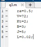
Before modelling some parameter has to be assumed which are as follows :-
- V=72 volt
- ra=0.5 ohms
- kϕ = 0.7 volt-second
- Kt=2
- B (damping constant)=3
- J (inertia constant) =5
- L(Inductance of motor)=0.02H
di/dt=(V-(Ia*ra)-k*dϴ/dt)*1/L
〖(dϴ)/dt〗^2 =(Kt*Ia-B*dϴ/dt)/J
ω">ω= V/Kϕ">ϕ -Ra/Kϕ">ϕ^2 *T
All the above equation are implemented in simulink model :-
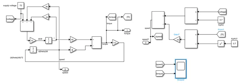
- The above model contains sone blocks as follows :-
- Add
- divide
- square
- gain
- intergrator
- goto and from
- scope
- constant
- outport
Torque and speed plot of the equation ω">ω= V/Kϕ">ϕ -Ra/Kϕ">ϕ^2 *T are shown below :-
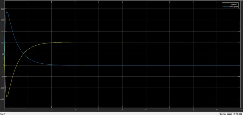
- In the above plot torque in Nm and speed in rad/sec are plotted.
- The plot in blue colour is of torque and plot is in yellow is of yellow.
- It is shown from the graph as speed increases the torque reduces as decaying exponential .
4. Refer to the blog on below topic:
Induction Versus DC brushless motors by Wally Rippel, Tesla
Explain in brief about author’s perspective.
Brushless DC motor (BLDC) :-
- Construction wise BLDC motor is different from Brushed DC motor.
- In BLDC motor permanent magnet is placed on rotor and coils are placed on stator.
- The movement of rotor is with the help of attraction and repulsion principle .
- On the stator three coils are placed and they are switched on and off according to rotor rotational position which is determine by position sensor with the help of Hall effect.
- For switching the stator supply current and electronic control is required that is inverter.
- BLDC motor are also known as self synchronous AC motor , variable frequency synchronous motor, permanent magnet synchronous motor(PMSM) and electronically commutated motor(ECM).
Three phase Induction motor (IM):-
- Construction wise IM has stator and rotor ,stator of IM are supplied from three phase ac source and rotor is squirrel cage or slip ring.
- As three phase supply is given to stator it producess alternating magnetic field and it cutts rotor conductor to induced emf in rotor .
- Due to which rotor generates its own magnetic field and the interaction of two magnetic field results in torque in IM.
Comparision between two motors :-
- Both motors that is BLDC and Induction motor are widely used in electric vehicle .
- Less heat is generated ,easy cooling and peak point efficiency is much higher in case of BLDC than induction motor.
- Starting torque of BLDC is relatively more as compared to IM.
- BLDC power factor is good than IM.
- Eddy and hysterisis loss can be minimised by reducing magnetic flux density "B" .But the control of B cannot been easy in case of BLDC .
- Control of B can be easily done in case of induction motor as B is proportional to V/f.
- As machine size of BLDC increases magnetic losses are increase proportionally but this is not the case in induction machine.
- Without the inverter BLDC is useless and in IM also inverter is used for the conversioN of DC to AC .
Finally as per the author perpective :-
- Both the motor has it own advantage and disadvantage and they have there dominance in there respective position where it have been used.
- As BLDC has good peak point efficiency so it has its dominance in hybrid and plug in hybrid vehicle market.
- While if we see overall performance of induction motor is good so it has dominance in pure electric vehicle market.
- So, as there hardware is nearly similar they can work side by side in EV and HEV.