Week 7 State of charge estimation
1.Simulate the 3 test cases from harness dashboard and write a detailed report on the results.
Solution:
Open the BMS model available in file exchange.
Click on the System and open BMS_Closesloop_Harness-Dashboard file.
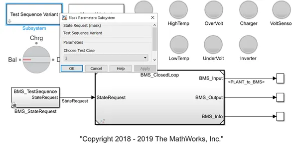
Test state transition:
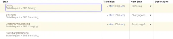
In Test Case 1 the transition is stated as
The cell balancing is for 3000 seconds,
balancing for 1000 seconds, and then Cell charging and balancing for 5000 seconds.
So totally the simulation for 9000 seconds is under the logic and after 9000 seconds the cell goes into the state of balancing mode.
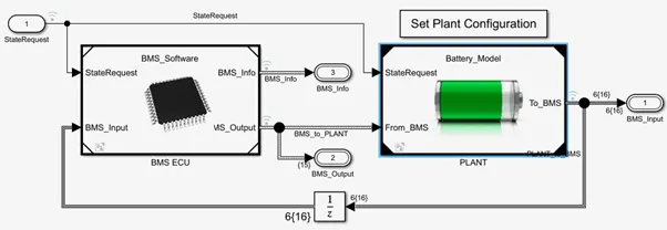
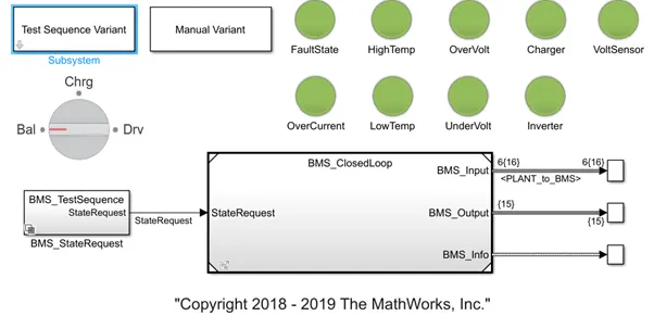
This is the BMS_closed loop block which is consisting of BMS_Control unit and Plant.
Plots of cell voltages, Battery_Current, BMS_state, Cell_Balancing, Cell_temperatures and SOC
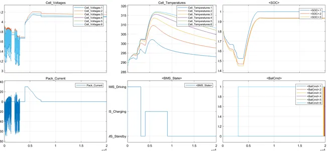
The above plot shows the results in Test case-1.
The test harness is running for 20000 seconds. In which time 0.3X10⁴ says that it is completing 3000 seconds. In plot BMS_state, 3000sec is indicating with Driving mode. In driving mode, Pack_current is fluctuating between +20A and -70 A. Cell voltages are fluctuating between 3.15V to 3.9v. The temperature of the cell is gradually increasing from 290Kelvins to 303kelvins. Soc of the battery is decreasing from 0.8 to 0.45. Cell balancing is maintained constant in this Driving period. From 3000sec to 4000 seconds, the mode is in Standby mode which shows the rise in temperature, Constant raise in Current, raise in voltage, raise in Cell temperatures, and Balancing. Bus SOC maintained constant in 3000 seconds to 4000 seconds says that the vehicle mode is standstill.
From 4000 seconds to 9000 seconds, the battery reached charging mode. In this mode, the vehicle is not driving. But it is charging. In this mode, pack_current decreased gradually and reached 0. Cell voltage reached 4.2 V. Cell temperatures gradually decreased and SOC of the battery reached 80%. Cell balancing was also maintained constant.
The simulation entered into standby mode in the next time period. Which controlled all other parameters to the constant values.
Test case:2
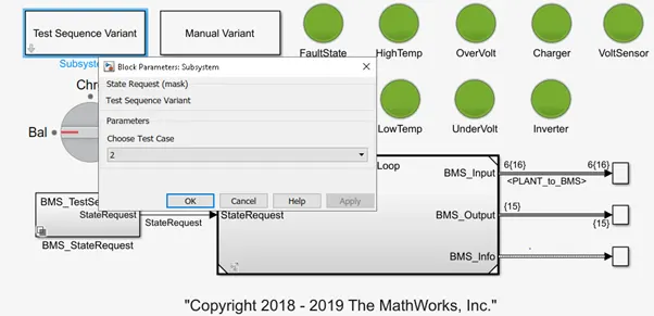
Test Logic:
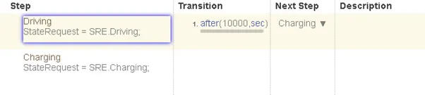
In Case 2 the model condition is the driving for 10000 seconds.
As the driving condition is continuous, the system result varies accordingly compare to test case 1 as Test case 1 includes driving, standby, and charging modes.
Test case 2 indicates only driving.
For the battery pack modeled, the results are as shown below
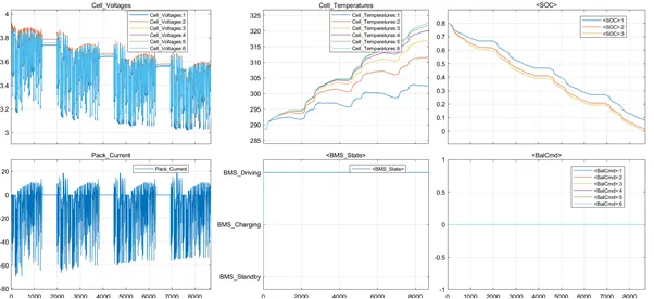
It shows in BMS_State is constantly in Driving mode. The Balance command is constantly 0 says that the Cell balancing is neutral. Pack current varies from +18 A to -60 A as the cells are discharging in driving mode. Cell voltage is varying from +3.9v to +3.1 v. Cell temperatures are increasing in temperature. SOC is ranging from 80 % to 0% as time reaching 8000 sec.
The model is simulated for 10000sec but the model is running up to 8000 seconds as the SoC is reaching 0% the plot shows in the above-said range.
Test Case:3
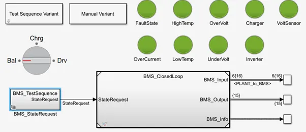
State Logic:
In this test case, the system is Charging.

Test Case 3 says only charging mode.
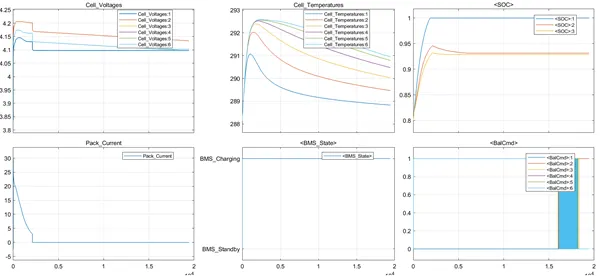
In this mode, BMS_state is continuously charging and Balancing is made as 1.
The state of charge of the battery reached 100 % and 94% for SOC_2 and SOC_3. Cell voltages are maintained constant as there is no discharge. Cell temperatures are maintained from 293k to 289 k where there is no huge temperature change. Pack_Current is maintained to 0A as there is no driving mode in this test case.
It is observed that when the battery pack is charging, the cell voltages, temperature, current changes are not huge. Balancing and state of BMS are maintained constant and SOC is also reached to 100 percent and maintained constant charging.
2.What is coulomb counting? Refer to the above model and explain how BMS implements coulomb counting for SOC estimation?
Solution:
The Coulomb counting method measures the discharging current of a battery and integrates the discharging current over time to estimate SOC. Coulomb counting method is done to estimate the SOC(t), which is estimated from the discharging current, I(t), and previously estimated SOC values, SOC(t-1).
SOC is calculated by the following equation:

Several factors affect the accuracy of the coulomb counting method, including temperature, battery history, discharge current, and cycle life.
Reference: https://www.hindawi.com/journals/isrn/2013/953792/
BMS is implemented in the plant sub-system.
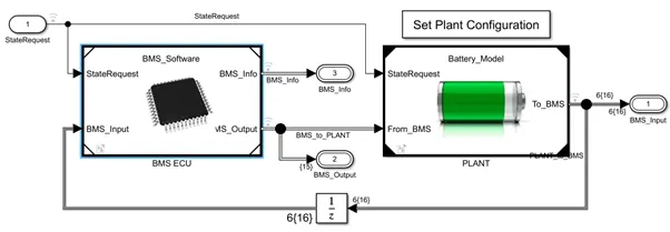
Battery estimation is given in coulomb counting logic.
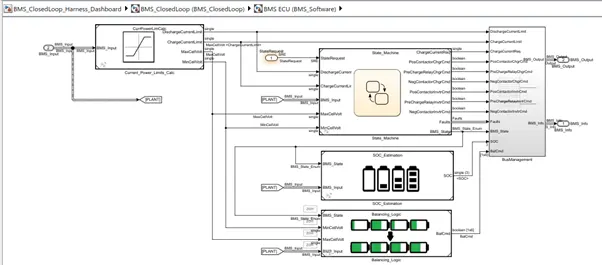
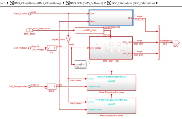
Coulomb counting logic circuit is as shown below.
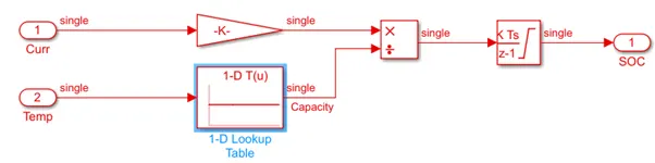
In the above model coulomb counting is the logic used in comparing with the previous value and summating the current and temperature.
Coulomb counting is simple and low computational cost.
Temperature and current from the battery are given as inputs.
The current signal is given to the gain block which is multiplied with 1/3600.
Temperature is given with lookup table
These inputs are integrated with respect to time which estimates the SOC of the battery.