Week 7: Shock tube simulation project
- Shock tube simulation project.
- Objective -The main goal of this project was to set up a transient simulation of a shock absorber tube using Converge CFD. A shock tube with a membrane in between, with one side of the tube filled with high-pressure nitrogen and the other side filled with low-pressure oxygen.
- Introduction
- A shock tube typically consists of a cylindrical tube of constant cross-section, divided into two chambers by a frangible membrane stretched across the tube.
- The two chambers initially have different gas pressures, creating a pressure differential across the membrane.
- A shock tube is a device used to reproduce and direct pressure waves onto a sensor or model, usually simulating a real explosion and its effects on a small scale.
- Shock tubes (and associated impact facilities such as impact tunnels, expansion tubes, and expansion tunnels) can also be used to study aerodynamic flow over a wide range of temperatures and pressures that are difficult to achieve in other types of test facilities.
- Shock tubes are also used to study compressible flow phenomena and combustion reactions in the gas phase. More recently, shock tubes have been used in biomedical research to study how biological samples are affected by pressure waves.This report details a shock tube simulation problem using Converg CFD software, solved with CYGWIN, and post-processes the results with ParaView. This case study contains a rectangular duct with two sections and a membrane between them.
- A high pressure reservoir is connected to the low pressure section.
- The Shock Tube is a device for studying shock waves. A membrane inside the tube blocks all flow before starting the experiment. You can increase the pressure on one side. B. At the compressor, then tear the membrane to start the flow.
- Gas expands in the other half of the tube.
- Procedure
- Geometry
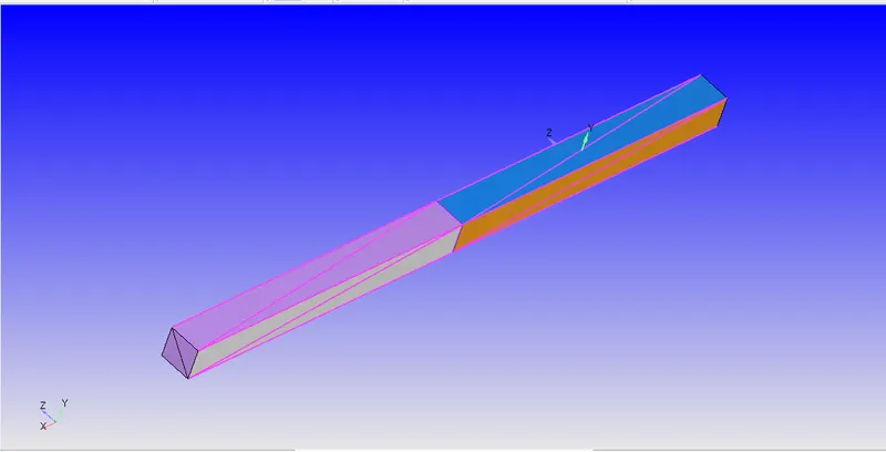
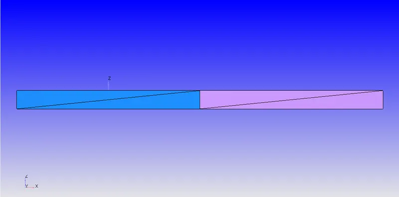
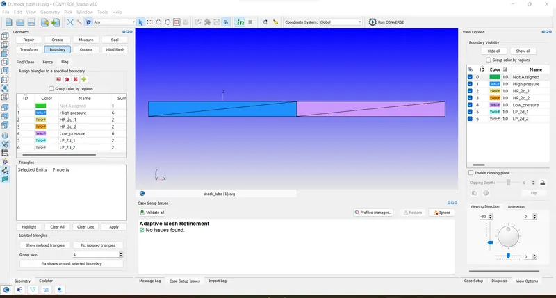
- Applying boundaries and Boundary conditions
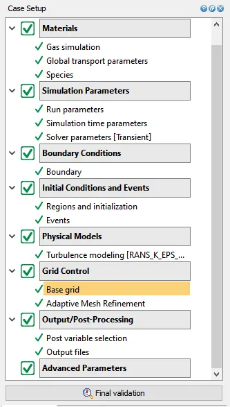
- Case Setup Dock.
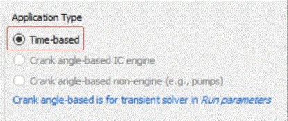
Application Type:
In order to run a steady-state simulation, firstly, under the Application type in the setup tree, a "Time-based" simulation must be selected.
Materials:
Under the material tab "Gas simulation" was selected and "Air" as a predefined mixture.
Gas: Air
Global Transport Parameters: Fixed value
by default, the following value is considered.
Prandtl Number : 0.9
Schmidt Number : 0.78
Species: Oxygen-O2 & Nitrogen-N2
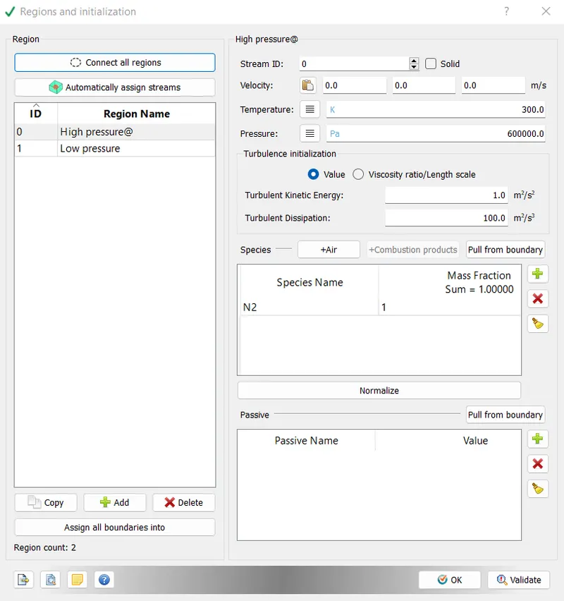
- The concept of events in Converge Studio:
Events should be used when two areas meet without boundaries. Event flags create triangles at points between two regions called connecting triangles.
Event flags can be enabled prior to case setup by going to the Initial Conditions window and checking the Events option.
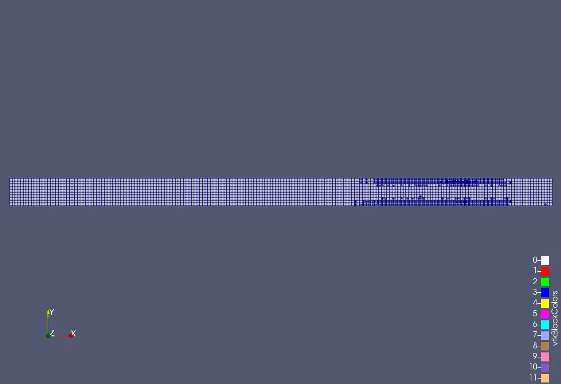
- Mesh
- Velocity contour
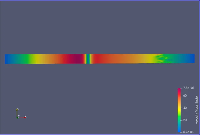
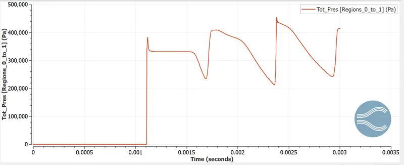
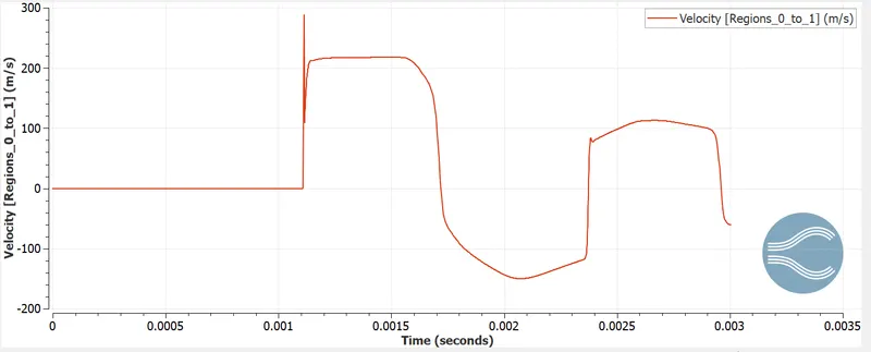
- The nitrogen velocity changes in the high pressure region and the oxygen velocity is zero in the low pressure region until the membrane ruptures. Here, after membrane rupture, a sudden increase in velocity, temperature, and pressure due to a pressure difference of 498975 Pa between the two regions forms mini-shock waves that move back and forth periodically throughout the rest of the simulated behavior.
- Pressure contour
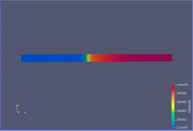
- From the pressure contour, we can conclude that both species share a common pressure, since after some time the pressure increases for one and decreases for the other.
- Temperature contour
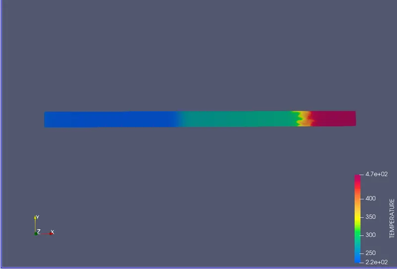
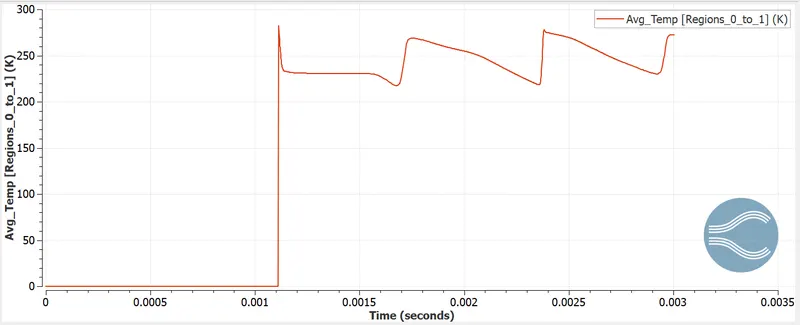
- The temperatures first fluctuate then will attend the equilibrium position after some time.Due to the increased static pressure in the low pressure zone, the temperature also increases. It should be noted that these two fluid properties are interdependent according to thermodynamics.
- Total cells count plot
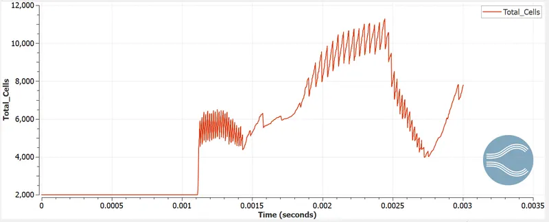
- From the cell count plot, we can see that the cell count is stable down to 0.001 seconds at 2000 cells. We find that upon membrane rupture, adaptive mesh subdivision occurs, resulting in fluctuating cell numbers and subsequent increases in cell numbers. This process continues until the end time when the cell count reaches 12000 cells.
- Pressure Plot
- Velocity plot
- Temperature plot
- Animation Link
- https://drive.google.com/drive/folders/1aTG-k5imlBaAZQUmJ11U6dD8jxt1ysgN?usp=share_link
- Stepwise Explaination
- Assuming you have 3D geometry placed in the Converge workspace.
- Borders are appropriately named.
- Normal direction checks consistency between geometry and flow.
- Diagnostics are running to check for geometry anomalies.
- Next, species suitable for the region are selected.
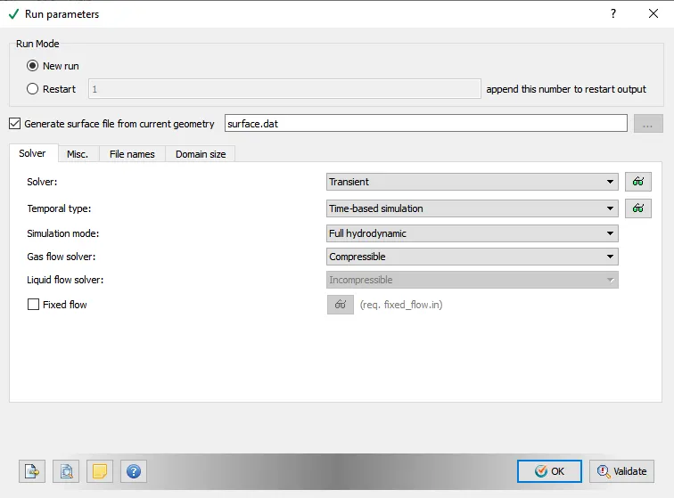
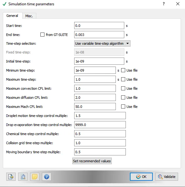
- Simulation parameters and corresponding time steps are set.
- Boundary conditions are set to the correct area and correct values.
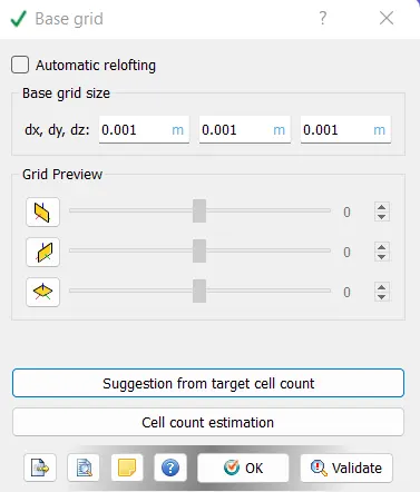
- A ground grid of considered pitches is inserted with each orientation and his AMR of three embedding layers with seed SGS of 0.001 is used.
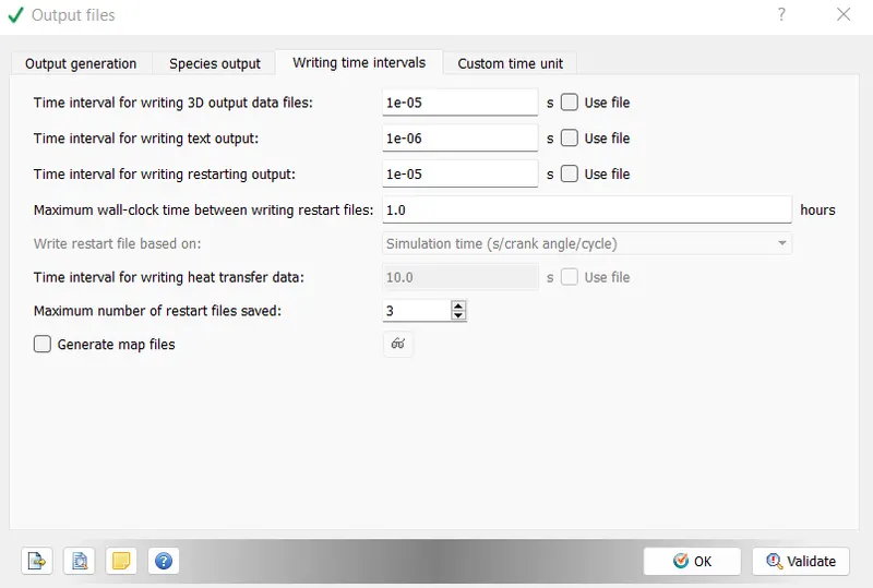
- Sets and selects post-processing variables and time intervals for writing output and resume files.
- All input files are saved in the desired location.
- All saved input files are executed using the command editor. The Converge Solver runs these input files in the background.
- The executed file then generates an output folder where data files are saved after each selected cycle interval. This folder will be post-processed for graphical results.
- Contours of flow parameters are plotted in paraview.
- Conclusion
- From this problem, we can understand the compressibility of gases and study their flow.
- With adaptive mesh refinement, cell counts are constantly changing as expansion and contraction occur within the shock absorber tube.
- The high pressure N2 gas compresses the low pressure O2 and after some compression recirculation takes place and the low pressure gas passes through his N2.
- A shock wave is reflected when the gas in the low pressure region is compressed and the pressure in the low pressure region is higher than the shock front.
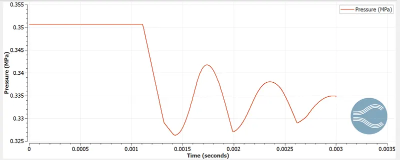
- This sinusoidal damping behavior is observed until the pressure difference becomes zero. In addition, shocks raise the temperature and expansion waves lower it.
- When the membrane suddenly ruptures, the high-pressure gas flows through the low-pressure gas area, creating a shock wave and increasing the pressure and temperature.
- The event option was enabled only as an alternative to membranes. This is either because the simulation cannot blast, or such conditions do not exist in Converge CFD.