Week 7 - Minor Project
- Aim: To perform flow analysis over a NACA0012 airfoil for subsonic and supersonic flow regimes, and also perform the simulations for 3 angle of attacks 5, 10 and 15. Calculate the drag and lift co-efficients and post-process the flow physics behaving on the aerofoil.
- Theory:
1. Angle of attack:
angle of attack (AOA, α, or  ) is the angle between a reference line on a body (often the chord line of an airfoil) and the vector representing the relative motion between the body and the fluid through which it is moving. Angle of attack is the angle between the body's reference line and the oncoming flow. This article focuses on the most common application, the angle of attack of a wing or airfoil moving through air.
In aerodynamics, angle of attack specifies the angle between the chord line of the wing of a fixed-wing aircraft and the vector representing the relative motion between the aircraft and the atmosphere. Since a wing can have twist, a chord line of the whole wing may not be definable, so an alternate reference line is simply defined. Often, the chord line of the root of the wing is chosen as the reference line.
2. Subsonic regime:
The subsonic speed range is that range of speeds within which, all of the airflow over an aircraft is less than Mach 1. The critical Mach number (Mcrit) is lowest free stream Mach number at which airflow over any part of the aircraft first reaches Mach 1. So the subsonic speed range includes all speeds that are less than Mcrit.
3. Supersonic regime:
The supersonic speed range is that range of speeds within which all of the airflow over an aircraft is supersonic (more than Mach 1). But airflow meeting the leading edges is initially decelerated, so the free stream speed must be slightly greater than Mach 1 to ensure that all of the flow over the aircraft is supersonic. It is commonly accepted that the supersonic speed range starts at a free stream speed greater than Mach 1.3.
4. Drag co-efficient:
The drag coefficient (commonly denoted as:  ,
,  or
or  ) is a dimensionless quantity that is used to quantify the drag or resistance of an object in a fluid environment, such as air or water. It is used in the drag equation in which a lower drag coefficient indicates the object will have less aerodynamic or hydrodynamic drag. The drag coefficient is always associated with a particular surface area.
5. Lift co-efficient:
The lift coefficient (CL) is a dimensionless coefficient that relates the lift generated by a lifting body to the fluid density around the body, the fluid velocity and an associated reference area. A lifting body is a foil or a complete foil-bearing body such as a fixed-wing aircraft. CL is a function of the angle of the body to the flow, its Reynolds number and its Mach number. The section lift coefficient cl refers to the dynamic lift characteristics of a two-dimensional foil section, with the reference area replaced by the foil chord
6. Compressible and incompressible flows:
Incompressible flow means flow with variation of density due to pressure changes is negligible or infinitesimal. All the liquids at constant temperature are incompressible. Compressible flow means a flow that undergoes a notable variation in density with trending pressure.
The property of volume change is called compressibility and a fluid whose volume changes is called compressible fluid. On the other hand, an incompressible fluid is a fluid which is not compressed or expanded, and its volume is always constant. In reality, a rigorous incompressible fluid does not exist.
- Case setup:
1. Geometry:
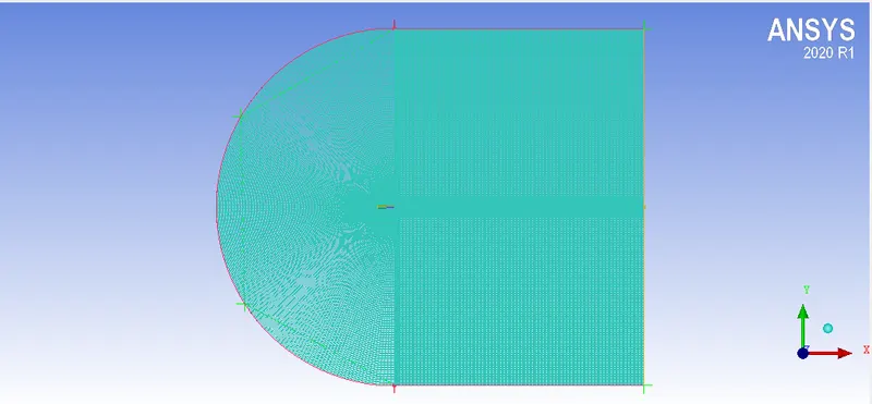
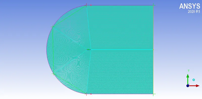
- Import the mesh file from ICEM CFD onto mesh, having given the name selection and defining the fluid volume in the meshing process in ICEM CFD, we can directly jump onto fluent.
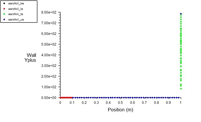
- Compressible:
Y-plus:
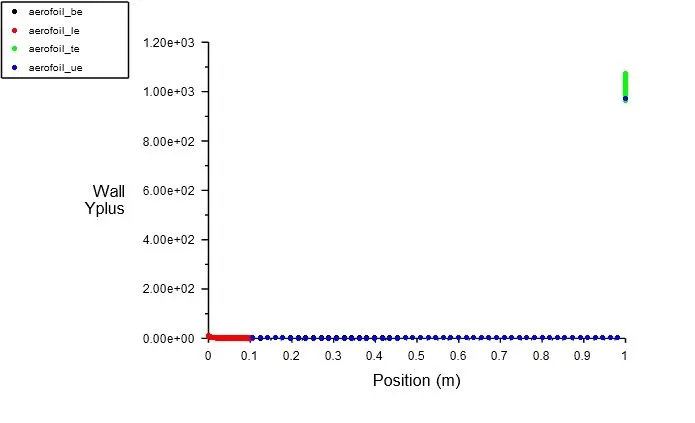
- Incompressible:
Y-plus:
2. Fluent Setup:
- General:
Steady state, absolute velocity, Pressure based, Plannar
- Boundaries:
Inlet- Velocity specifications method: Components
Outlet- 0 gauge pressure
- Turbulence models:
k-omega SST model
- Post-processing:
Velocity contour
Pressure Conotur
Coefficient of drag and lift
- Calculation:
End time step: 400
time step size: 1
3. Results:
AOA 5:
a. Incompressible:
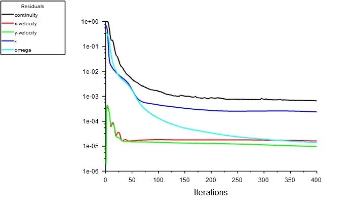
- Residuals:
- Velocity contour:
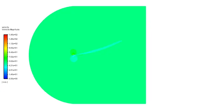
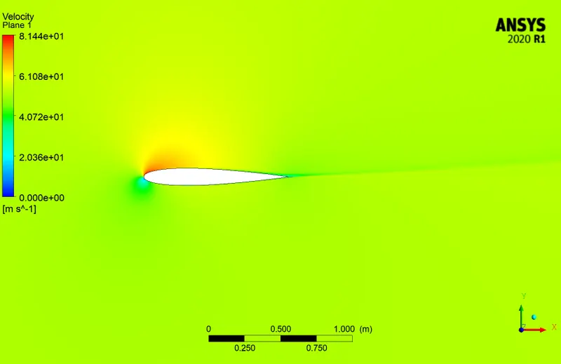
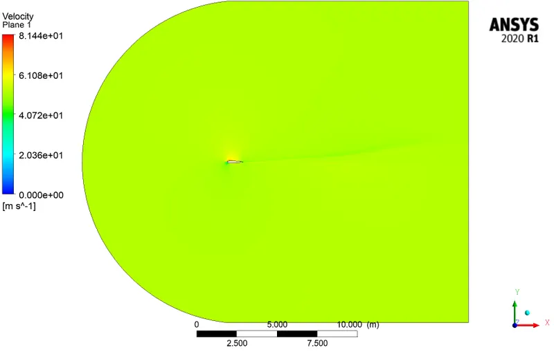
- Pressure contour:
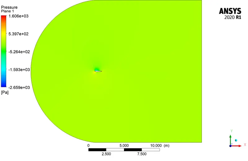
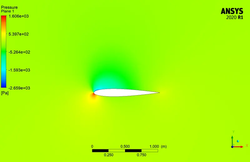
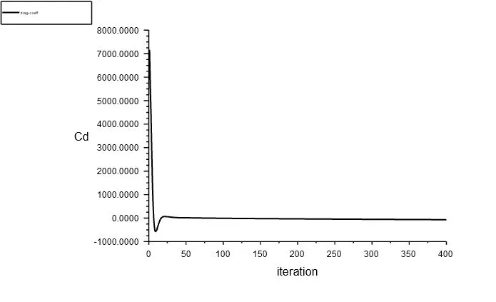
- Drag co-efficient:
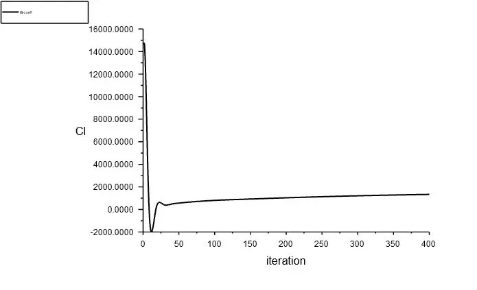
- Lift co-efficient:
b. Compressible:
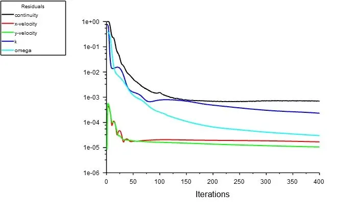
- Residuals:
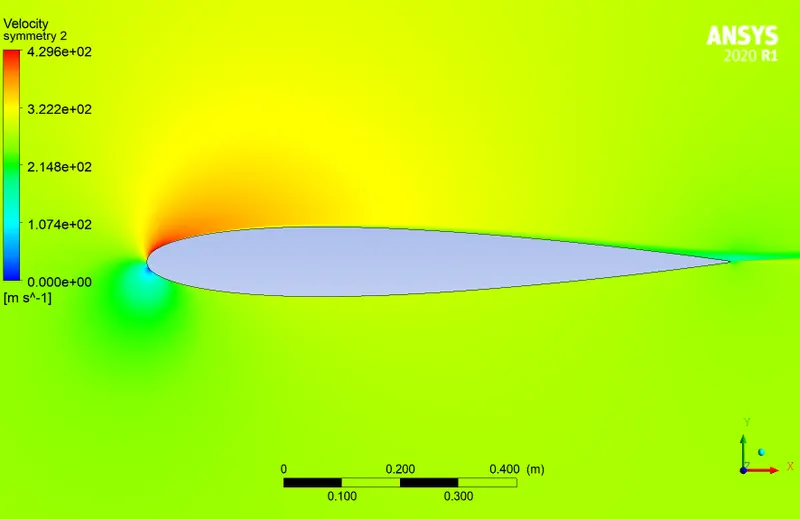
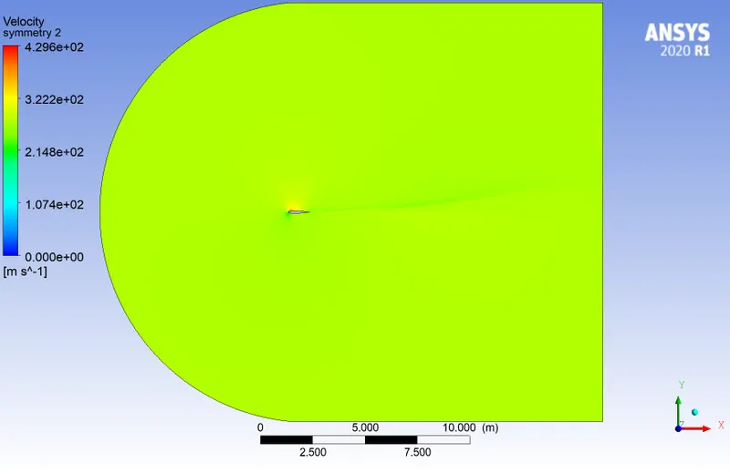
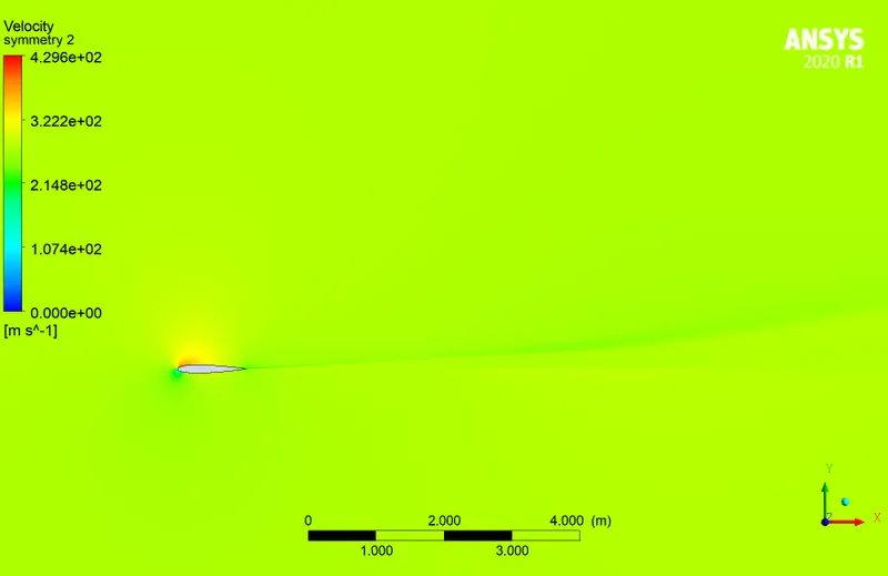
- Velocity contour:
- Pressure contour:
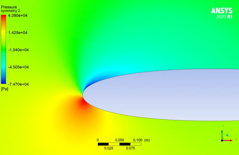
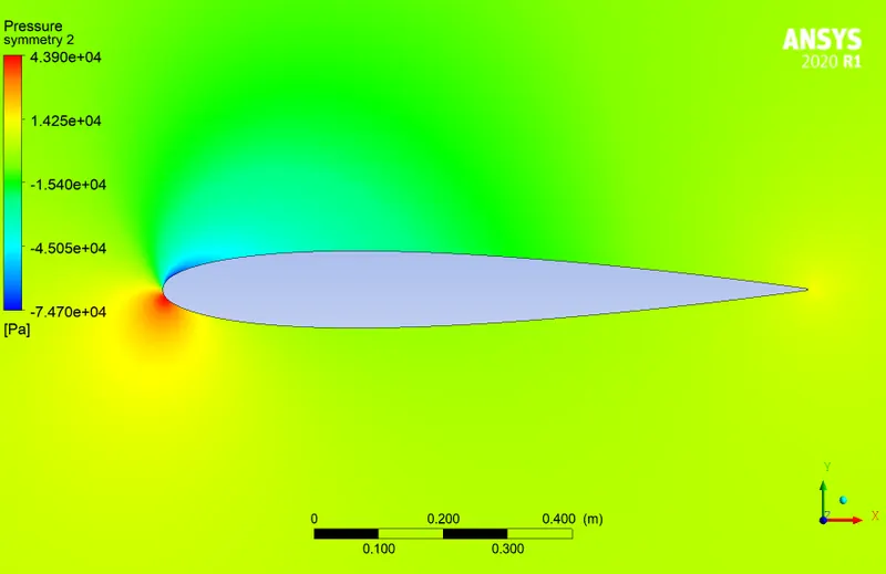
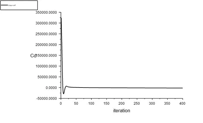
- Drag co-efficient:
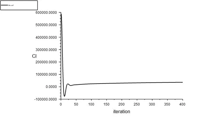
- Lift co-efficient:
AOA 10:
a. Incompressible:
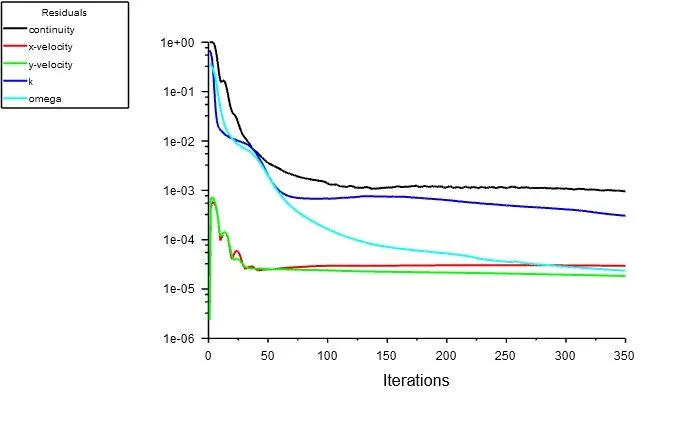
- Residuals:
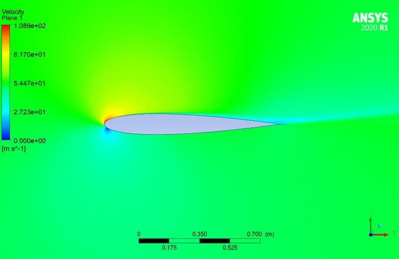
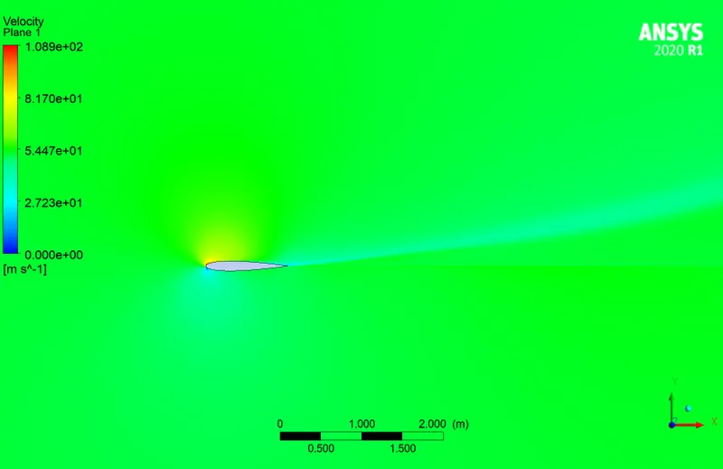
- Velocity contour:
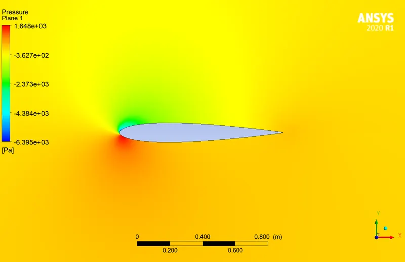
- Pressure contour:
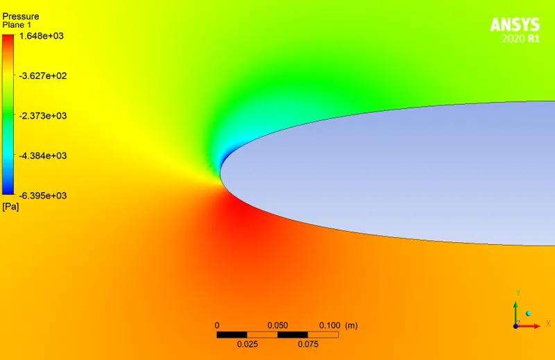
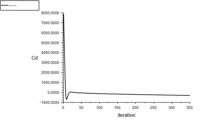
- Drag co-efficient:
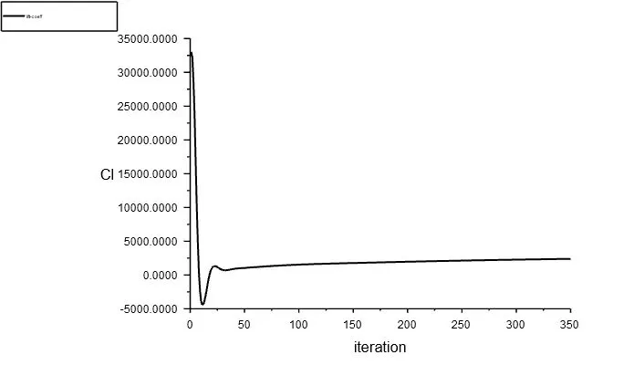
- Lift co-efficient:
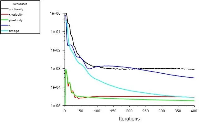
b. Compressible:
- Residuals:
- Velocity contour:
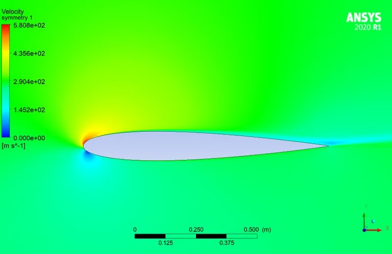
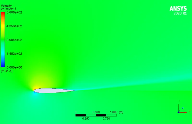
- Pressure contour:
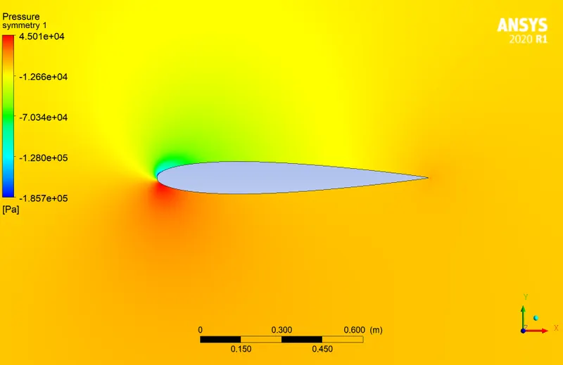
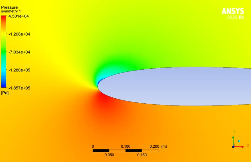
- Drag co-efficient:
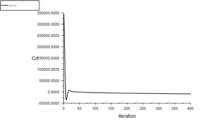
- Lift co-efficient:
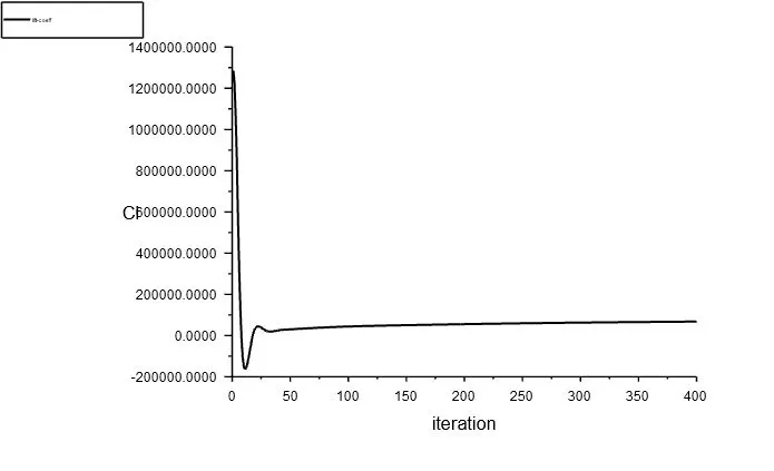
AOA 15:
a. Incompressible:
- Residuals:
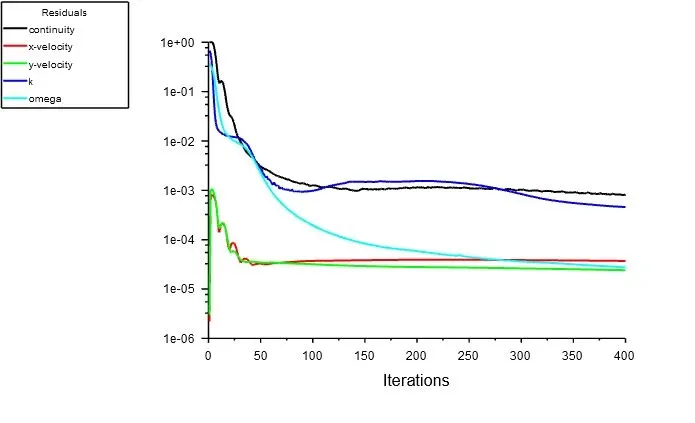
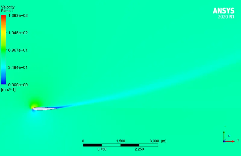
- Velocity contour:
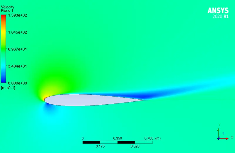
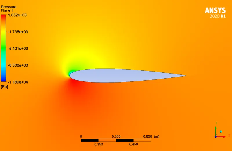
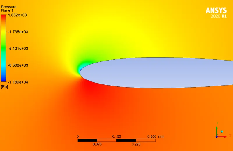
- Pressure contour:
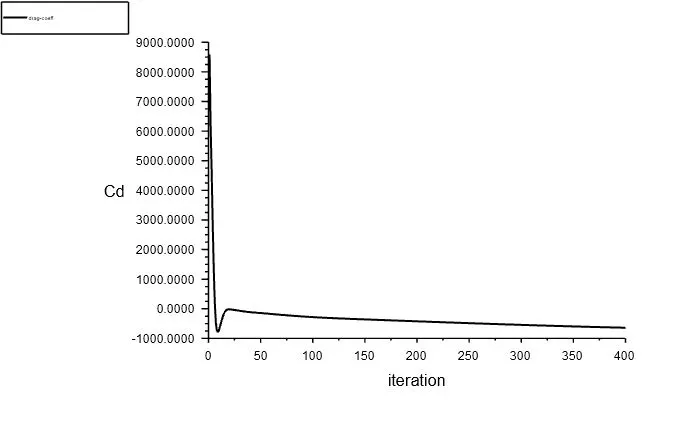
- Drag co-efficient:
- Lift co-efficient:
b. Compressible:
- Residuals:
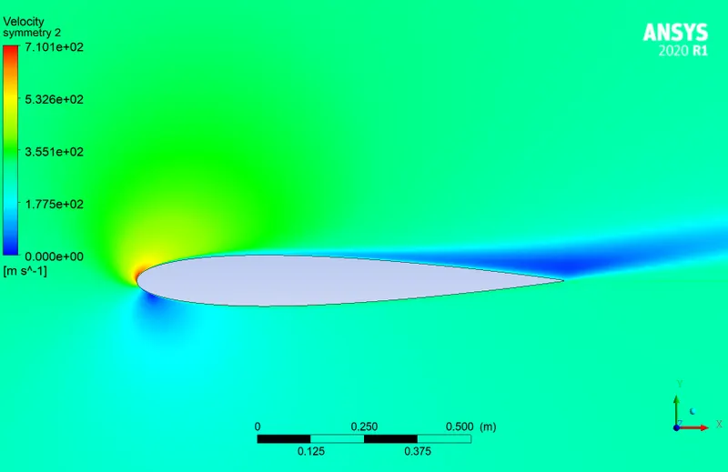
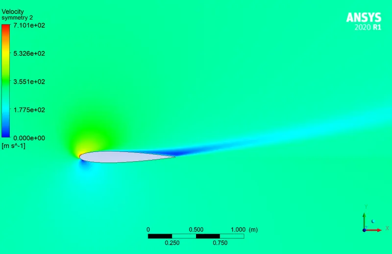
- Velocity contour:
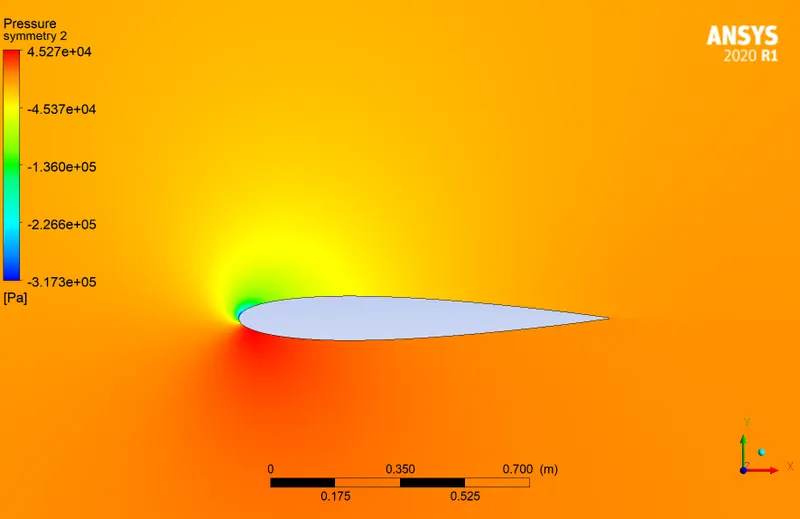
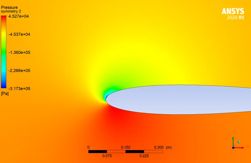
- Pressure contour:
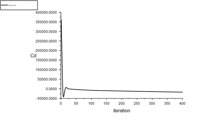
- Drag co-efficient:
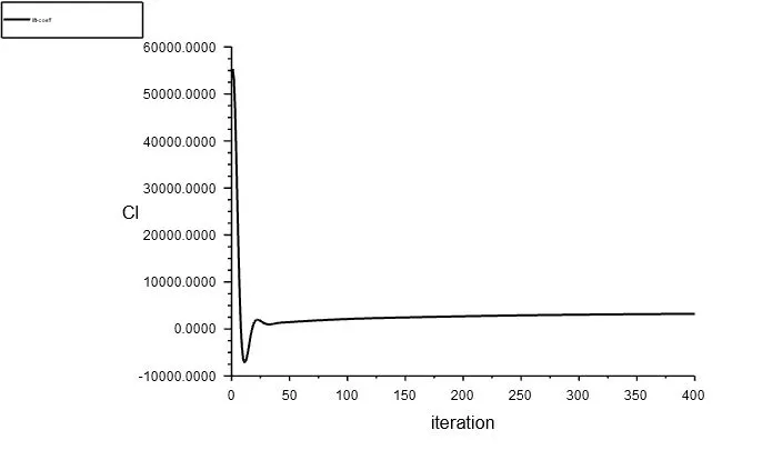
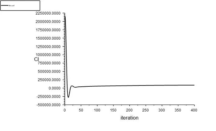
- Lift co-efficient:
4. Conclusion:
| Incompressible | Compressible | |||||
| AOA (degree) | 5 | 10 | 15 | 5 | 10 | 15 |
| Cd | -67.33 | -300.64 | -640.05 | -1882.72 | -8833.2 | -17274.2 |
| Cl | 1333.84 | 2393.29 | 3234.21 | 36531.3 | 68005.8 | 89927.82 |
| Vmax (m/s) | 81.44 | 108.9 | 139.3 | 429.6 | 580.8 | 710.1 |
| Pmax (Bar) | 0.0160 | 0.0164 | 0.01652 | 0.439 | 0.45 | 0.4529 |
- It is observed from the above table that at higher speeds and max AOA of 15degree, maximum lift is produced.
- Maximum velocity is achieved at the slat region of the airfoil where flow separation occurs and fluids velocity increases drastically over the airfoil.
- Good quality mesh structured mesh was achievd using ICEM CFD and imported onto fluent case setup
- Convergence was achieved after 500 iterations running at steady state uisng k-omega SST turbulence model.