Week 7 - Minor Project
AIM:
To simulate flow over an airfoil for three different Angle of Attack to find out the Lift and Drag coefficient values.
PROCEDURE TO SET UP THA CASE FOR SIMULATION:
GEOMETRY:
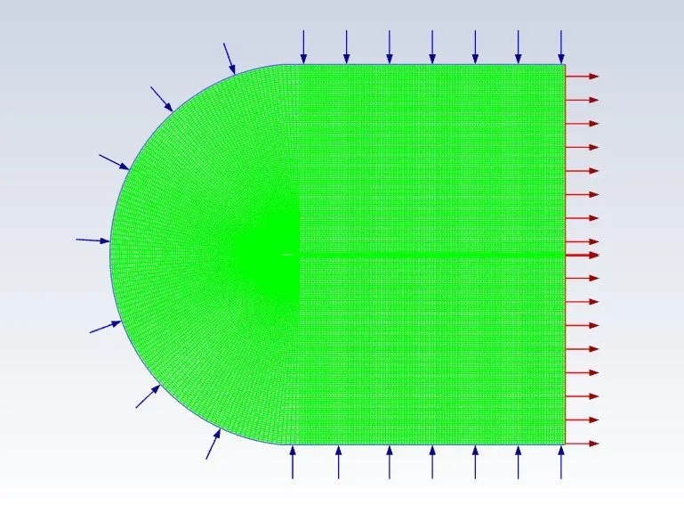
- Import the mesh file to fluent.
- Display all parts and check the mesh report.
TURBULENCE MODEL & MATERIALS:
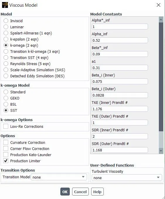
- Here SST k-omega is used.
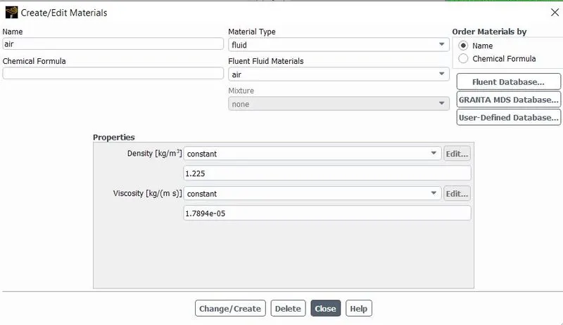
- Air is used as fluid material with constant parameters.
BOUNDARY CONDITIONS:
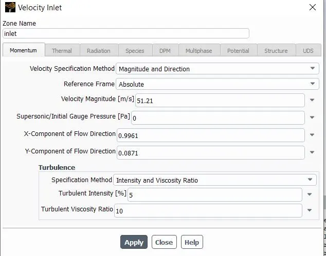
- Inlet as Velocity inlet with 51.21m/s.
- The outlet is considered a pressure outlet.
- For AOA 5 degree X-component flow direction is calculated as `cos(5)`.
- For AOA 5 degree Y-component flow direction is calculated as `sin(5)`.
- These steps are similar for different AOA.
SOLUTION METHOD AND REPORT DEFINITIONS:
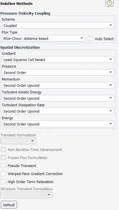
- Coupled scheme and second-order spatial discretization method are used.
- The Courant number is reduced to 10.
- The coefficient of drag and Coefficient of lift report definition is created.
INITIALIZATION AND RUN CALCULATION:
- Standard initialization is computed from the inlet.
- For calculation 1000 iterations are set.
RESULT:
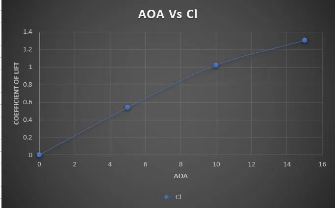
Graph of AOA Vs Cl:
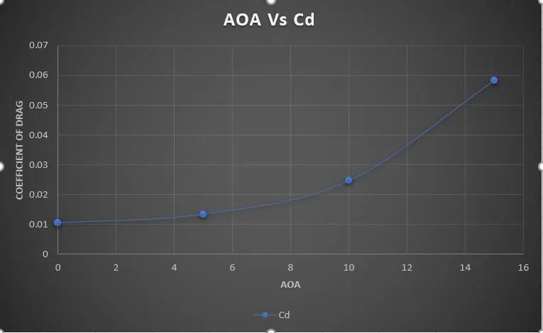
Graph of AOA Vs Cd:
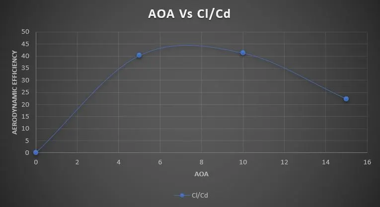
Graph for Aerodynamic Efficiency:
CONCLUSION:
From this simulation, we came to know how to simulate flow over an airfoil with different AOA and to calculate Cl, Cd and aerodynamic efficiency.