Week 7 - Minor Project
Aim:
To setup a simulation of flow over NACA 0012 Airfoil at subsonic and supersonic Regimes for three different Angle Of Attacks (AOA).
Introduction:
An airfoil (American English) or aerofoil (British English) is a streamlined body that is capable of generating significantly more lift than drag. Wings, sails and propeller blades are examples of airfoils. Foils of similar function designed with water as the working fluid are called hydrofoils.When oriented at a suitable angle, a solid body moving through a fluid deflects the oncoming fluid (for fixed-wing aircraft, a downward force), resulting in a force on the airfoil in the direction opposite to the deflection.This force is known as aerodynamic force and can be resolved into two components: lift (perpendicular to the remote freestream velocity) and drag (parallel to the freestream velocity).The lift on an airfoil is primarily the result of its angle of attack. Most foil shapes require a positive angle of attack to generate lift, but cambered airfoils can generate lift at zero angle of attack. Airfoils can be designed for use at different speeds by modifying their geometry: those for subsonic flight generally have a rounded leading edge, while those designed for supersonic flight tend to be slimmer with a sharp leading edge. All have a sharp trailing edge.The air deflected by an airfoil causes it to generate a lower-pressure "shadow" above and behind itself. This pressure difference is accompanied by a velocity difference, via Bernoulli's principle, so the resulting flowfield about the airfoil has a higher average velocity on the upper surface than on the lower surface. In some situations (e.g. inviscid potential flow) the lift force can be related directly to the average top/bottom velocity difference without computing the pressure by using the concept of circulation and the Kutta–Joukowski theorem.
The wings and stabilizers of fixed-wing aircraft, as well as helicopter rotor blades, are built with airfoil-shaped cross sections. Airfoils are also found in propellers, fans, compressors and turbines. Sails are also airfoils, and the underwater surfaces of sailboats, such as the centerboard, rudder, and keel, are similar in cross-section and operate on the same principles as airfoils. Swimming and flying creatures and even many plants and sessile organisms employ airfoils/hydrofoils: common examples being bird wings, the bodies of fish, and the shape of sand dollars. An airfoil-shaped wing can create downforce on an automobile or other motor vehicle, improving traction.When the wind is obstructed by an object such as a flat plate, a building, or the deck of a bridge, the object will experience drag and also an aerodynamic force perpendicular to the wind.
With increased angle of attack, lift increases in a roughly linear relation, called the slope of the lift curve. At about 18 degrees this airfoil stalls, and lift falls off quickly beyond that. The drop in lift can be explained by the action of the upper-surface boundary layer, which separates and greatly thickens over the upper surface at and past the stall angle. The thickened boundary layer's displacement thickness changes the airfoil's effective shape, in particular it reduces its effective camber, which modifies the overall flow field so as to reduce the circulation and the lift. The thicker boundary layer also causes a large increase in pressure drag, so that the overall drag increases sharply near and past the stall point.
Asymmetric airfoils can generate lift at zero angle of attack, while a symmetric airfoil may better suit frequent inverted flight as in an aerobatic airplane. In the region of the ailerons and near a wingtip a symmetric airfoil can be used to increase the range of angles of attack to avoid spin–stall.
A laminar flow wing has a maximum thickness in the middle camber line. Analyzing the Navier–Stokes equations in the linear regime shows that a negative pressure gradient along the flow has the same effect as reducing the speed. So with the maximum camber in the middle, maintaining a laminar flow over a larger percentage of the wing at a higher cruising speed is possible. However, some surface contamination will disrupt the laminar flow, making it turbulent. For example, with rain on the wing, the flow will be turbulent. Under certain conditions, insect debris on the wing will cause the loss of small regions of laminar flow as well. Before NASA's research in the 1970s and 1980s the aircraft design community understood from application attempts in the WW II era that laminar flow wing designs were not practical using common manufacturing tolerances and surface imperfections. That belief changed after new manufacturing methods were developed with composite materials (e.g. laminar-flow airfoils developed by Professor Franz Wortmann for use with wings made of fibre-reinforced plastic). Machined metal methods were also introduced. NASA's research in the 1980s revealed the practicality and usefulness of laminar flow wing designs and opened the way for laminar-flow applications on modern practical aircraft surfaces, from subsonic general aviation aircraft to transonic large transport aircraft, to supersonic designs
The geometry of the airfoil is described with a variety of terms :
1.The leading edge is the point at the front of the airfoil that has maximum curvature (minimum radius)
2.The trailing edge is defined similarly as the point of maximum curvature at the rear of the airfoil.
3.The chord line is the straight line connecting leading and trailing edges. The chord length, or simply chord is the length of the chord line. That is the reference dimension of the airfoil section
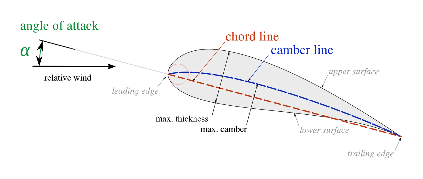
4.The mean camber line or mean line is the locus of points midway between the upper and lower surfaces. Its shape depends on the thickness distribution along the chord
5.Angle of Attack (AOA) is the angle between the line of the chord of an aerofoil and the relative airflow.
Theory:
A fluid flow is classified as being internal or external, depending on whether the fluid flows in a confined space or over a surface. The flow of an unbounded fluid over a surface such as a plate, a wire, or a pipe is external flow.
Differentiate the body into two types based on their geometry.They are
(i)A bluff body can be defined as a body that, as a result of its shape, has separated flow over a substantial part of its surface. Any body which when kept in fluid flow, the fluid does not touch the whole boundary of the object. An important feature of a bluff body flow is that there is a very strong interaction between the viscous and inviscid regions.When the flow separates from the surface and the wake is formed,the pressure recovery is not complete. The larger the wake, the smaller is the pressure recovery and the greater the pressure drag. Examples of bluff bodies include cylinders, spheres, and brick-like shapes.Bluff bodies experience pressure drag as the dominant component of drag.Pressure drag arises because of the large low-pressure zone produced in the wake at the rear of the body.
(ii)Slender bodies are characterized by their gradual tapering shape, which smoothly narrows towards a sharp point or edge.Examples of slender bodies include airfoils (such as wings) and streamlined shapes like fish.Slender bodies operate at small angles of attack relative to the freestream flow direction.In terms of drag, slender bodies experience viscous drag (skin friction drag) as the dominant source of air resistance.Viscous drag occurs due to the friction between the body’s surface and the surrounding air.The art of streamlining a body lies, therefore,in shaping its contour so that separation, and hence the wake, is eliminated, or atleast in confining the separation to a small rear part of the body and, thus, keeping the wake as small as possible. Such bodies are known as streamlined bodies
In this,Going to simulate Flow over NACA 0012 Airfoil.NACA 0012 Airfoil is a streamline body.The NACA 0012 airfoil is a symmetric airfoil with zero camber, meaning it has no curvature along its chord line and it's thickness has 12% of the chord length and maximum thickness occurs at 30% of the chord length.Cordinates can be calculated by using this formula
`y=underset(-)(+)0.594689181*[0.298222773*sqrt(x)-0.127125232*x-0.357907906*x^2+0.29198497*x^3-0.105174606*x^4]`
x-coordinates on the chord length.
Prediction of flow is laminar or turbulent is based on one dimensionless number i.e.., Reynolds Number
`Re=frac{rho*V*L}{mu}`
if Re>`5xx10^5` flow will be turbulent and vice versa
A flow is classified as being compressible or incompressible, depending on the level of variation of density during flow. Incompressibility is an approximation, in which the flow is said to be incompressible if the density remains nearly constant throughout.The densities of liquids are essentially constant, and thus the flow of liquids is typically incompressible. Therefore, liquids are usually referred to as incompressible substances. A pressure of 210 atm, for example, causes the density of liquid water at 1 atm to change by just 1 percent. Gases, on the other hand, are highly compressible. A pressure change of just 0.01 atm, for example, causes a change of 1 percent in the density of atmospheric air. When analyzing rockets, spacecraft, and other systems that involve high speed gas flows, the flow speed is often expressed in terms of the dimensionless Mach number defined as
`Ma=V/c`
Ma-Mach Number
V-Flow speed
c-speed of sound in medium
Speed of sound derived using mass flow rate,energy balance and thermodynamic relations `Tds=dh-frac{dP}{rho}`,then
`c=sqrt(gammaxxRxxT)`
`gamma-`Specific heat index
R-Universal Gas constant
T-Absolute Temperature in Kelvin
Stagnation pressure for incompressible flow is calculated by using formula,
`underset(0)(P)=P+frac{1}{2}*rho *V^2`
Stagnation pressure for compressible flow is calculated by using formula,
`frac{underset(0)(P)}{P}=(1+frac{(gamma-1)}{2}*Ma^2)^frac{gamma}{gamma-1}`
`T=underset(0)(T)*(frac{P}{underset(0)(P)})^frac{gamma-1}{gamma}`
Liquid flows are incompressible to a high level of accuracy, but the level of variation of density in gas flows and the consequent level of approximation made when modeling gas flows as incompressible depends on the Mach number. Gas flows can often be approximated as incompressible if the density changes are under about 5 percent, which is usually the case when Ma < 0.3. Therefore, the compressibility effects of air at room temperature can be neglected at speeds under about 100 m/s. Note that for low-speed flows, the stagnation and static (or ordinary) temperatures are practically the same. But for high-speed flows, the temperature measured by a stationary probe placed in the fluid (the stagnation temperature) may be significantly higher than the static temperature of the fluidCompressibility effects should never be neglected for supersonic flows, however, since compressible flow phenomena like shock waves occur.
A shock wave, like any wave, is a disturbance moving through a medium. They are thin wavefronts that cause sudden changes in the pressure, temperature, and density of the medium.Shock waves are caused in supersonic flows. This is when something is traveling at a speed faster than the speed of sound in the medium.
When an object moves through a medium at a low speed, the mach number is less than one. In this case, the waves in the medium moving outward from it will be symmetrical or almost symmetrical in all directions.When it picks up speed, the waves in front of it will get compressed. They will have more frequency and the waves behind it will have less frequency. The waves in front tighten up the faster the object moves, until we reach the speed of sound.At the speed of sound, the mach number is equal to one, at which point waves will be tightening and overlapping at the front of the object.So what happens once the moving object exceeds the speed of sound? The waves are unable to adjust or catch up and are left behind, so to speak. The trailing waves create the shape of an expanding cone.That's How shock waves will get formed.
Different types of shockwaves.They are
(i)we consider shock waves that occur in a plane normal to the direction of flow, called normal shock waves. The flow process through the shock wave is highly irreversible and cannot be approximated as being isentropic.The flow is supersonic before the shock and subsonic afterward. Therefore the flow must change from supersonic to subsonic if a shock is to occur.Properties will change after flow across the shock as pressure increases,stagnation pressure decreases,Velocity decreases,Temperature increases ,stagnation temperature remains constant,Density increases and entropy increases.Normal shocks occur, for example, in supersonic internal and jet flows.
(ii) when the space shuttle travels at supersonic speeds through the atmosphere, it produces a complicated shock pattern consisting of inclined shock waves called Oblique Shock.we consider straight oblique shocks, like that produced when a uniform supersonic flow (Ma1 > 1) impinges on a slender.oblique shocks are possible only if the upstream flow is supersonic.Downstream of an oblique shock can be subsonic,sonic, or supersonic.shock angle between shock line and center line of the body,wedge angle is angle between centerline and the outerside of the body.deflection angle is the angle between deflected flowing fluid and shock line.Shock angle is smaller then weak oblique shock will be seen,if shock angle is larger then strong oblique shock will be seen. Thus, the flow downstream of a strong oblique shock is always subsonic . The flow downstream of a weak oblique shock remains supersonic.Maximum deflection angle such as 45.6 degree will appear for shock angle 67.8 degrees.there are two shock angles where there is no turning of the flow (deflection angle=0): the strong case, shock angle = 90 degrees, corresponds to a normal shock, and the weak case, shock angle = minimum shock angle , represents the weakest possible oblique shock at that Mach number, which is called a Mach wave.Across a shock wave, the static pressure, temperature, and gas density increases,the entropy of the entire system increases ,flow properties are irreversible,the total enthalpy and the total temperature are constant,total pressure decreases
(iii)If the wedge half-angle is greater than maximum defection angle, the shock becomes curved and detaches from the nose of the wedge, forming what is called a detached oblique shock or a bow wave.
(iv)The weakest possible oblique shock at that Mach number, which is called a Mach wave.Mach waves are caused, for example, by very small non-uniformities on the walls of a supersonic wind tunnel. Mach waves have no effect on the flow, since the shock is vanishingly weak. In fact, in the limit, Mach waves are isentropic.
(v) A continuous expanding region called an expansion fan appears, composed of an infinite number of Mach waves called Prandtl–Meyer expansion waves.In other words, the flow does not turn suddenly, as through a shock, but gradually—each successive Mach wave turns the flow by an infinitesimal amount.The Mach number downstream of the expansion increases , while pressure, density, and temperature decrease.Prandtl–Meyer expansion fans also occur in axisymmetric supersonic flows, as in the corners and trailing edges of a cone-cylinder .
Incompressible flow does not imply that the fluid itself is incompressible
In this,Going to simulate both types of flow such as compressible and incompressible flow.
In this simulation estimating a two significant parameters of external flow such as Lift and Drag.
The force a flowing fluid exerts on a body in the flow direction is called drag. Thus the drag force is due to the combined effects of pressure and wall shear forces in the flow direction The drag force can be measured directly by simply attaching the body subjected to fluid flow to a calibrated spring and measuring the displacement in the flow direction.The part of drag that is due directly to wall shear stress is called the skin friction drag since it is caused by frictional effects, and the part that is due directly to pressure is called the pressure drag.Friction Drag is a strong function of viscosity and increases with increasing viscosity.The friction drag coefficient is independent of surface roughness in laminar flow, but is a strong function of surface roughness in turbulent flow due to surface roughness elements protruding further into the boundary layer. The pressure drag is proportional to the frontal area and to the difference between the pressures acting on the front and back of the immersed body. when the velocity of the fluid is too high for the fluid to be able to follow the curvature of the body, and thus the fluid separates from the body at some point and creates a very low pressure region in the back. The pressure drag in this case is due to the large pressure difference between the front and back sides of the body.To reduce drag is to streamline a body in order to reduce flow separation and thus to reduce pressure drag. But streamlining has opposite effects on pressure and friction drag forces.In this ,going to simulate one of the streamlined body such as NACA 0012 airfoil
The components of the pressure and wall shear forces in the direction normal to the flow tend to move the body in that direction, and their sum is called lift.The pressure difference between the top and bottom surfaces of the wing generates an upward force that tends to lift the wing . For devices that are intended to generate lift such as airfoils, the contribution of viscous effects to lift is usually negligible since the bodies are streamlined, and wall shear is parallel to the surfaces of such devices and thus nearly normal to the direction of lift . Therefore, lift in practice can be approximated as due entirely to the pressure distribution on the surfaces of the body, and thus the shape of the body has the primary influence on lift.Also, at moderate angles of attack, lift is practically independent of the surface roughness since roughness affects the wall shear, not the pressure. The contribution of shear to lift is significant only for very small bodies that fly at low velocities .You have probably experienced giving a spin to a tennis ball or making a drop shot on a tennis or ping-pong ball by giving a fore spin in order to alter the lift characteristics and cause the ball to produce a more desirable trajectory and bounce of the shot. The phenomenon of producing lift by the rotation of a solid body is called the Magnus effect.
The drag and lift forces depend on the density of the fluid,the upstream velocity and the size, shape, and orientation of the body, among other things.
`underset(D)(F)=underset(A)(int)(-P*cos theta+underset(w)(tau)*sin theta)dA`
`underset(D)(F)-`Drag Force
`P-pressure`
`underset(w)(tau)-`Wall shear stress
`dA-`Change in area
`underset(L)(F)=underset(A)(int)(-P*sin theta+underset(w)(tau)*cos theta)dA`
`underset(L)(F)-`Lift Force
Dimensionless numbers that represent the drag and lift characteristics of the body .They are Drag and Lift coefficient
`underset(D)(C)=frac{underset(D)(F)}{frac{1}{2}*rho*V^2*A}`
`underset(L)(C)=frac{underset(L)(F)}{frac{1}{2}*rho*V^2*A}`
`underset(D)(C)-`Drag coefficient
`underset(L)(C)-`Lift coefficient
`rho-`Density of fluid
`V`-flow velocity
A-Area
The drag and lift coefficients are primarily functions of the shape of the body, but in some cases they also depend on the Reynolds number and the surface roughness.The local drag and lift coefficients vary along the surface as a result of the changes in the velocity boundary layer in the flow direction.As the velocity of the body increases, so does the drag force.
Simulation Procedure:
1.To start a simulation 2D NACA 0012 airfoil Geometry and mesh has been imported into the Fluent Solver
2.File->Read option is used and navigated the file to open the geometry and mesh part in the solver.
3.Initially considering temperature as 300K.Based on this speed of sound is calculated
c=`sqrt(gamma*R*T)`
`gamma`-adiabatic index ,For air=1.4
`R`-Specific gas constant-287.052874 `J.kg^-1.K^-1`
T-Absolute Temperature in K
`c=sqrt(1.4*287.052*300)`
c=347.22 `m/s`
Flow regimes are classified Based on Mach Number(Ma) as
i.Subsonic Flow (Ma < 0.8),
ii.Transonic Flow (0.8 < Ma < 1 & 1 < Ma < 1.2),
iii.Sonic Flow (Ma = 1),
iv.Supersonic Flow (Ma > 1.2),
v.Hypersonic Flow (Ma > 5)
*Ma represents the Free Stream Mach Number
Changes in Density greater than 5% and Mach No is greater than 0.3, then flow is said to compressible Flow.
if Mach No is less than 0.3 and changes in density is less than 5%,then flow is said to be incompressible Flow.
Our Simulation Based on subsonic and supersonic regimes , Selected a Ma = 0.15 on Subsonic Regime and Ma = 2.0 on Supersonic Regime to carry out the simulation
`Ma=V/c`
V-Flow Velocity,
c-Speed of sound in medium.
(i)For Subsonic Case,
`V=Maxxc`
`V=0.15xx347.22`=52.083 `m/s`
(ii)For Supersonic case,
`V=Maxxc`
`V=2xx347.22`=694.44 `m/s`
4.Domain->Mesh->Check->Perform Mesh check is selected to know that the mesh is valid.
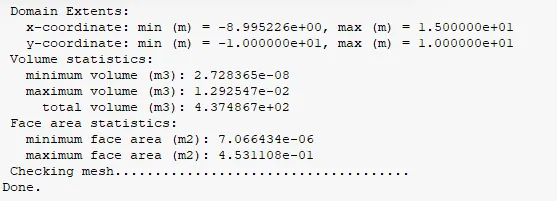
5.Domain->mesh->Quality->Evaluate Mesh Quality is selected to know the Critical mesh parameters

6.Physics->General->Pressure-Based solver(Subsonic case) ,Density-Based solver(Supersonic case) is selected ,remaining default option is used.
Energy checkbox turned on for supersonic regime.
Energy checkbox turned of for subsonic regime.
In supersonic regime,Physics->solver->Operating conditions,Operating pressure 0.
In sunsonic regime,Physics->solver->operating conditions,Operating pressure 101325 pa
7.Models->viscous->`K-omega`SST model is Selected, then the turbulence production term to sensitize the standard eddy-viscosity models to the effects of streamline curvature the curvature correction is selected then Ok.
8.Default air properties is used.Materials->air is selected.
In subsonic regime,density and viscosity constants has utilised.
In supersonic regime,Ideal gas law for density and sutherland law for viscosity has utilised.
9.Zones->CellZones->fluid then air material name is selected.
10.Zones->Boundaries is selected,
i.Aerofoil shape will have Wall Boundary condition
ii.For subsonic case,C-shape will have velocity-inlet Boundary condition
under the velocity specification method,components are selected.
`u=Vxx cos(alpha)`
`alpha-`Angle of Attack in degrees
`v=Vxxsin(alpha)`
u=X-direction velocity
v=Y-direction velocity
| S.No | Angle Of Attack (Degrees) | u-component Velocity in `m/s` | v-component Velocity in `m/s` |
| 1 | 5 | 51.884 | 4.539 |
| 2 | 10 | 51.291 | 9.044 |
| 3 | 15 | 50.308 | 13.480 |
iii.vertical Line that is connecting to C-shape ,Pressure-Outlet Boundary condition has assumed.
iv.In Supersonic Regime,Pressure Farfield Boundary condition has used for inlet,static temperature and pressure and Components of flow diretion(drag Froce vector x and y components present in the below table) displayed below has entered.
11.Physics->Solver->Reference Values is selected.Compute from Inlet and temperature has changed to 300K.
12.Solution->Methods->Pseudo time method->Off is selected.
13.Solution->Reports->Residuals->Check convergence checkbox is turned off for all parameters.
14.Solution->Reports->definitions->New->Force Report ->Drag ->Drag coefficient is selected and Force vector cordinates has entered and print to console is selected.
Force Vector X-component=`cos (alpha)`,Force Vector Y-component=`sin(alpha)`
| S.No | Angle of Attack (Degrees) | Force Vector X-Component | Force Vector Y-Component |
| 1 | 5 | 0.9961 | 0.0871 |
| 2 | 10 | 0.9848 | 0.1736 |
| 3 | 15 | 0.9659 | 0.2588 |
15.Solution->Reports->definitions->New->Force Report ->Lift ->Lift coefficient is selected and Force vector cordinates has entered and print to console is selected.
Force Vector X-component=`-Sin (alpha)`,Force Vector Y-component=`cos(alpha)`
| S.No | Angle of Attack (Degrees) | Force Vector X-Component | Force Vector Y-Component |
| 1 | 5 | -0.0871 | 0.9961 |
| 2 | 10 | -0.1736 | 0.9848 |
| 3 | 15 | -0.2588 | 0.9659 |
16.Additional convergence conditions has given by selecting solution->Reports->convergence
Changes in drag and lift on compared with previous iteration with critera 1e-7.if changes gone below the criteria iteration will stop.
All conditions should met.
17.Solution->initialisation->standard->options->Compute from inlet->Initialise is selected.
18.Results->Graphics->contour is selected ,for velocity and pressure
19.Solution->Activities->create->solution animations for creating an animation for pressure and velocity
20.FMG Initilisation is done
21.Solution->Run calculation->No.of.iterations-2000->Calculate is selected.
Plots/contours:
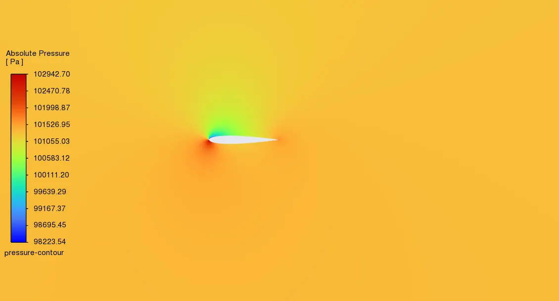
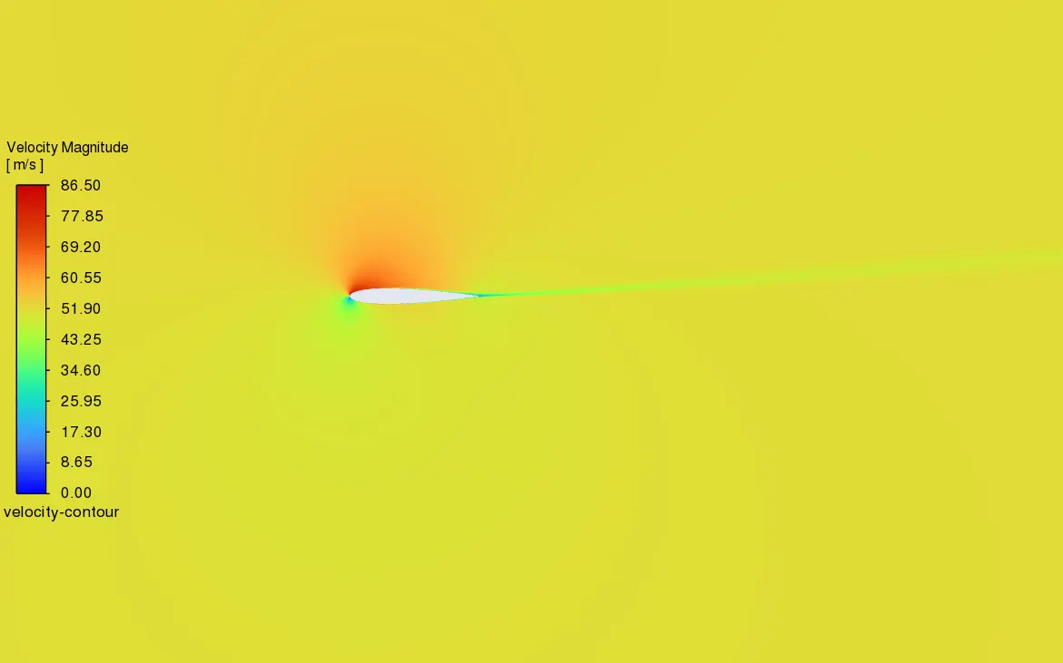
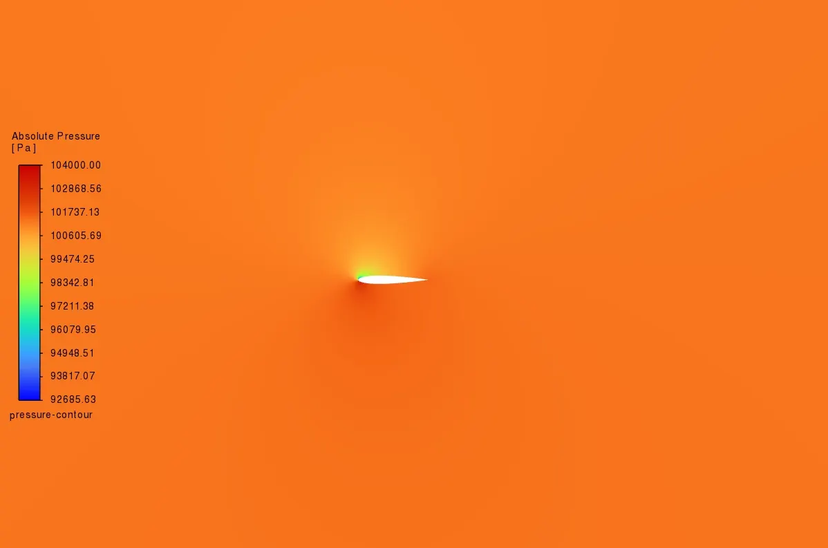
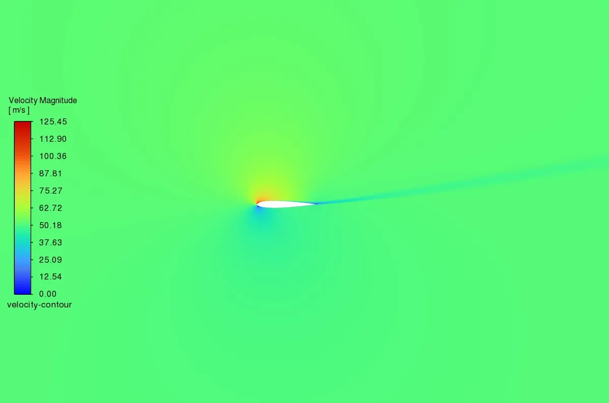
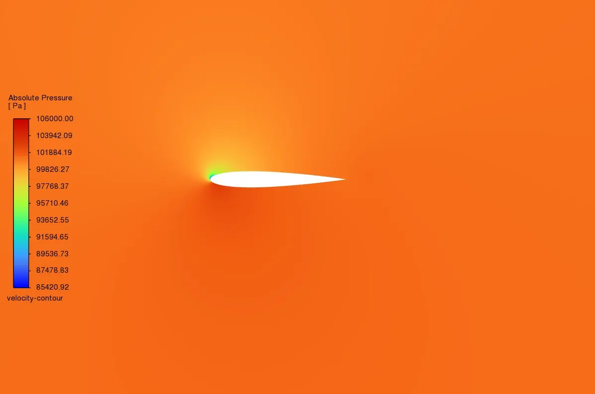
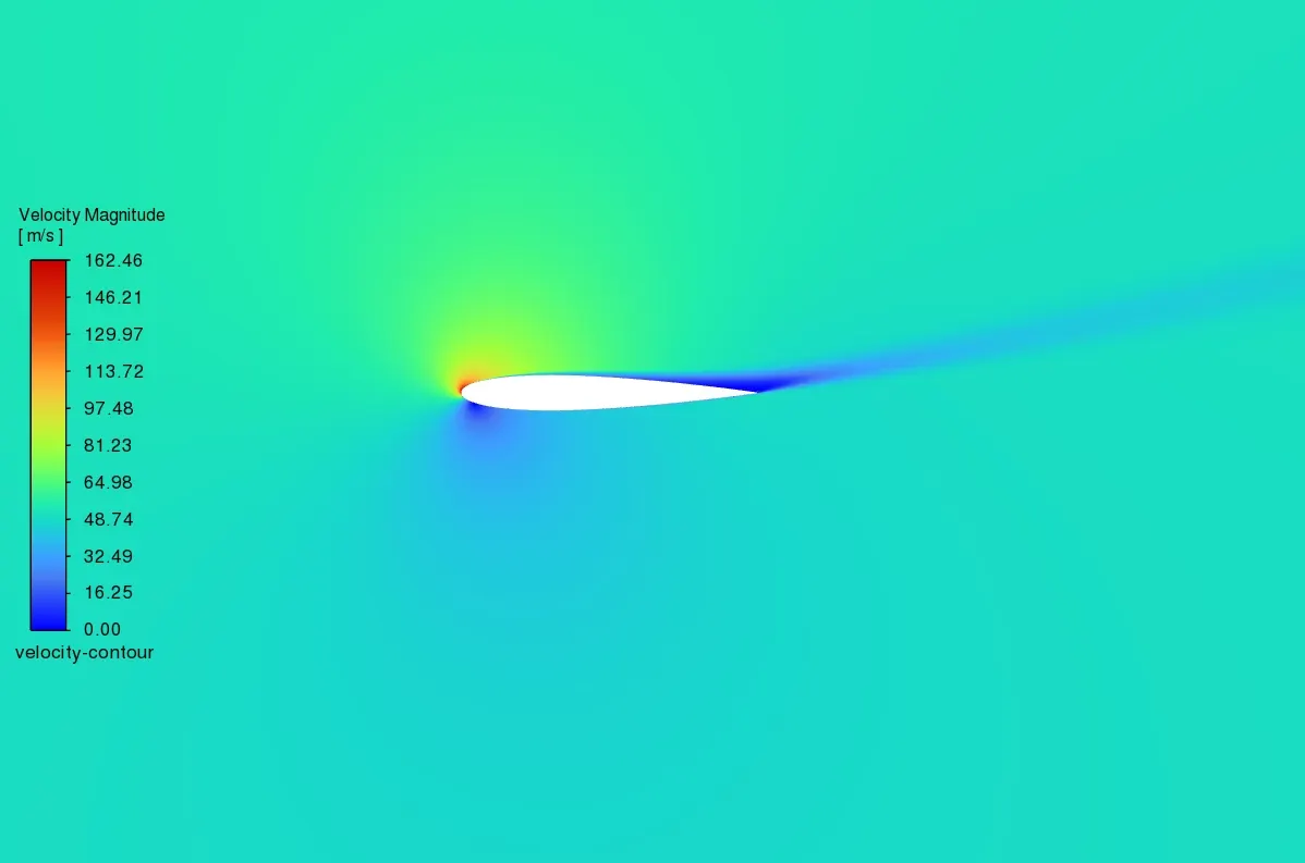
(i)incompressible,Ma-0.15
AOA-5 Degrees
AOA-10
AOA-15
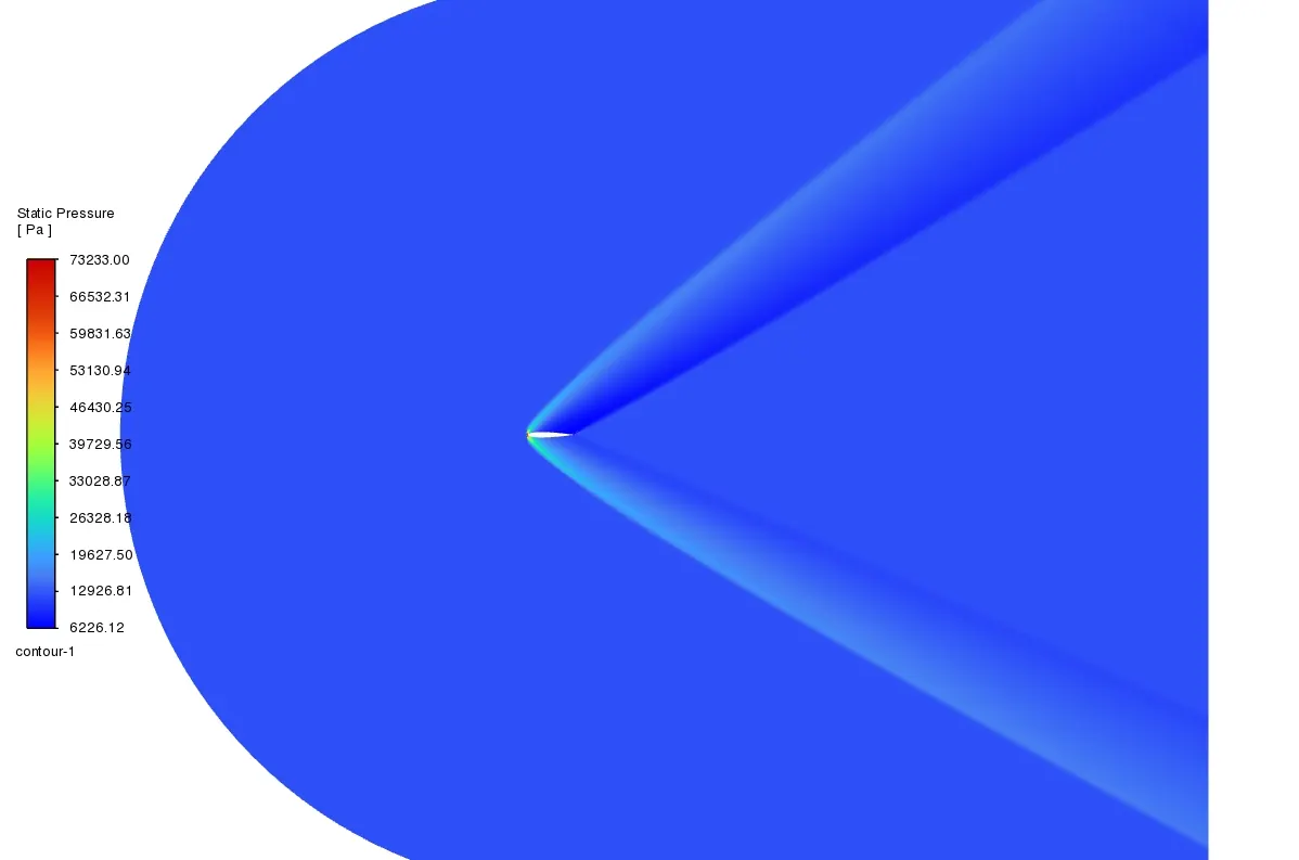
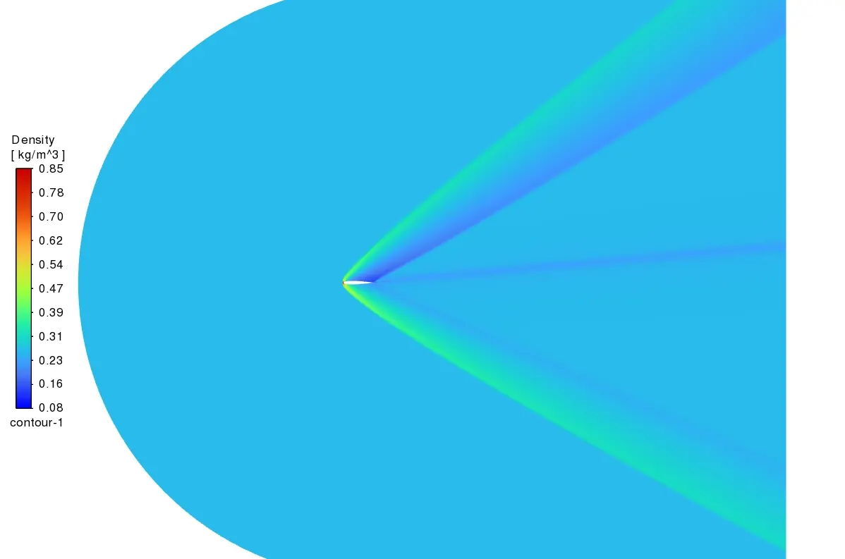
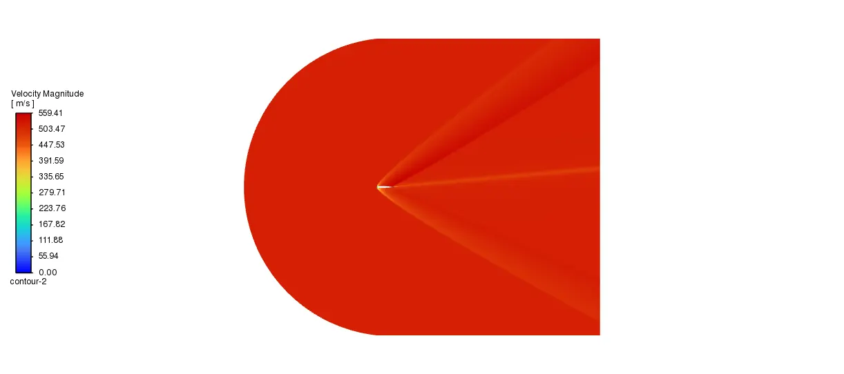
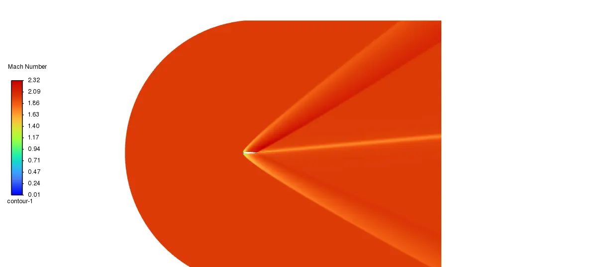
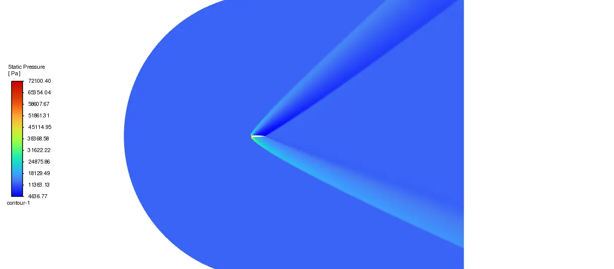
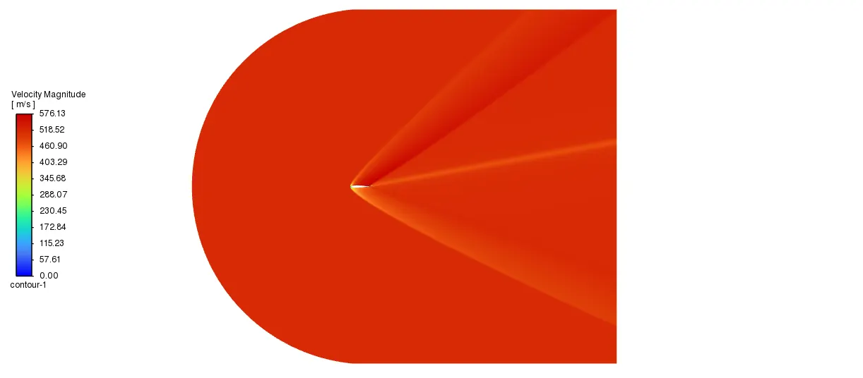
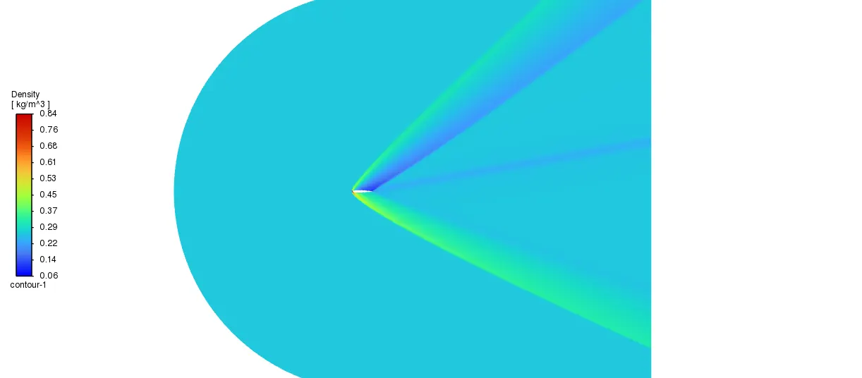
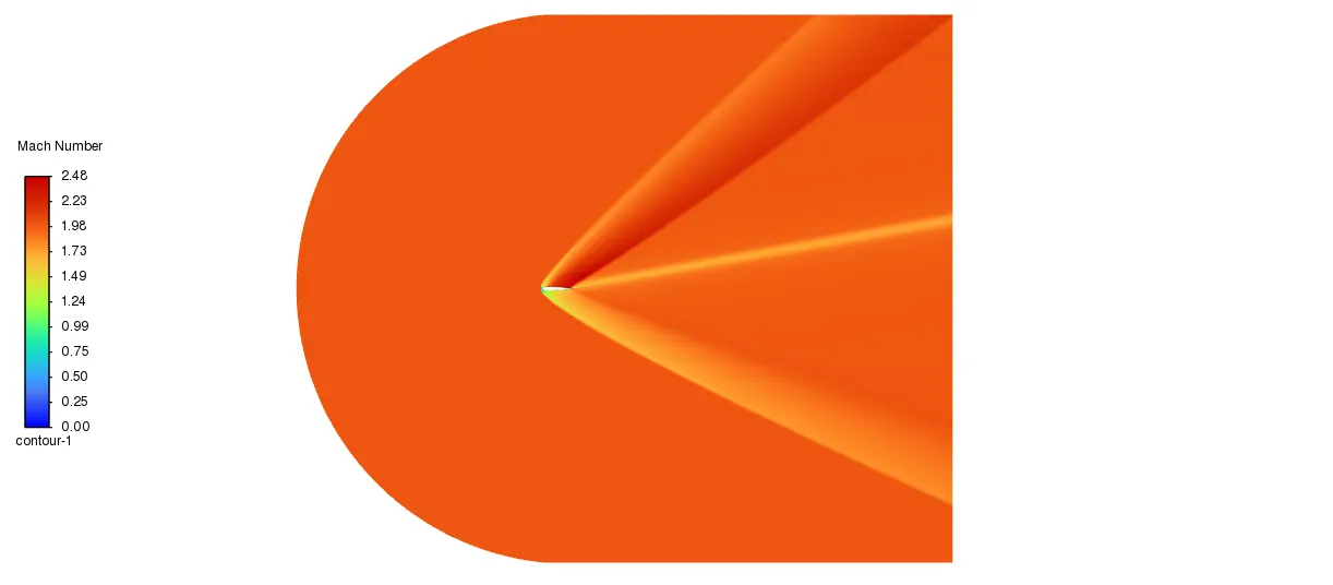
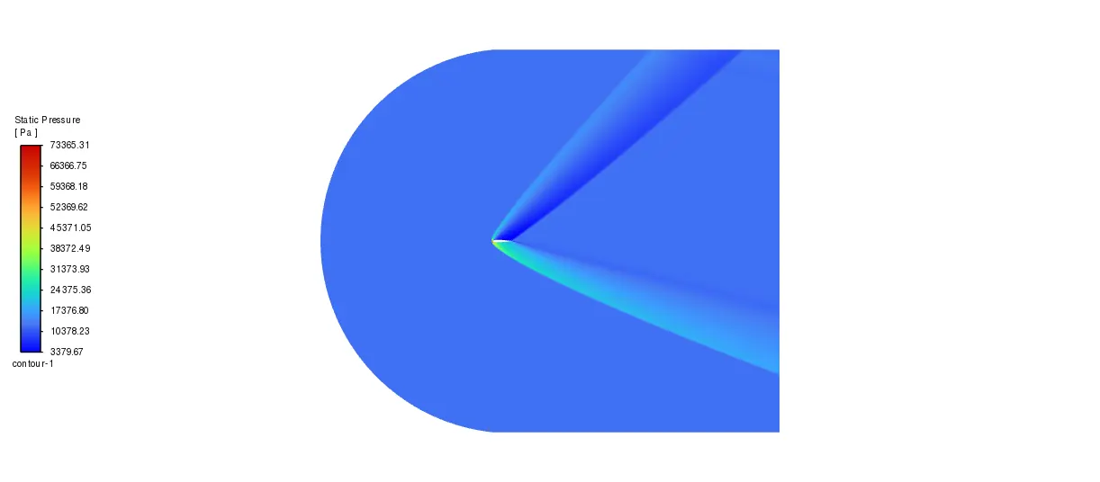
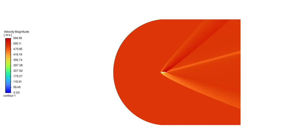
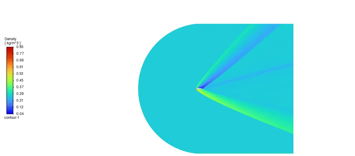
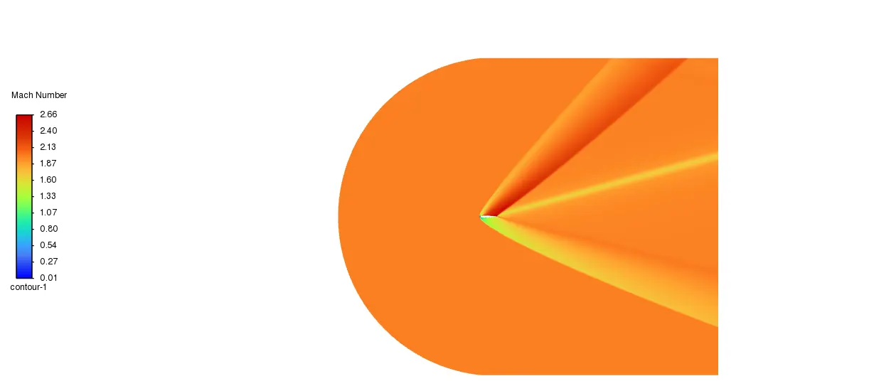
(ii)Compressible,Ma-2
AOA-5
AOA-10
AOA-15
Results:
| S.No | Mach Number (Ma) | Angle of Attack(AOA) in Degrees | Lift Coefficient | Drag Coefficient |
| 1 | 0.15 | 5 | 0.542 | 0.0103 |
| 2 | 0.15 | 10 | 1.042 | 0.0164 |
| 3 | 0.15 | 15 | 1.396 | 0.0337 |
| 4 | 2 | 5 | 0.181 | 0.1108 |
| 5 | 2 | 10 | 0.360 | 0.156 |
| 6 | 2 | 15 | 0.541 | 0.234 |
1.Drag and lift forces are directly proportional to their coefficients.As the simulation results are presented on the table
on Mach Number 0.15,Subsonic flow as the Angle Of Attack increases lift and drag coefficient increases
Similarly on supersonic flow,Mach Number 2 as the Angle of attack increases lift and drag coefficient increases
2.On subsonic flow,Minimum drag coefficient is 0.0103 on Angle of attack 5 Degrees and Maximum Lift coefficient is 1.396 for the 15 degree Angle of attack.similarly on supersonic flow,Minimum Drag coefficient is 0.181 for the 5 degree Angle of Attack and maximum lift coefficient is 0.541 for the 15 degree Angle of Attack.
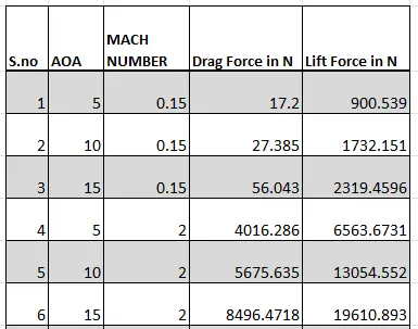
3.Lift Forces on Supersonic regime has high value when compared to the Subsonic Regimes.
4.Drag Forces on Supersonic regime has high value when compared to the Subsonic Regimes.
5.It is clearly on subsonic regime airfoil has very less drag coefficient and Force and better lift force and coefficient.
6.From the plots of incompressible,the Pressure increases with velocity decreases and vice versa.
7.From the plots of incompressible,the maximum and minimum pressure in the range and maximum velocity in the range gets widen as Angle of Attack (AOA)
8.From the plots of incompressible,the wake region increases as the Angle of Attack increases.
9.From the plots of compressible,presence of shockwave is seen and across the shock static pressure,density increases,velocity and mach number decreases.
10.From the plots of compressible,Mach number after shockwave is greater than 1.5,based on this can conclude as oblique shock wave
11.From the plots of compressible,Static pressure range maximum and minumum values decreases as Angle Of Attack increases,velocity magnitude maximum in range and Mach number maximum in range increases as AOA increases,Density range doesnot has a large change.
12.NACA 0012 airfoil performed well on subsonic regime when compared to supersonic regime.