Week 7 - Minor Project
Aim: To setup the domain for analysis of flow over an airfoil at subsonic and supersonic regime.
Objectives: Analysis at 3 different angles of attack (5, 10 & 15 deg) for the airfoil and comparision of the lift and drag coefficient in all cases.
Theory:
During flight, the behavior of airflow over an aircraft changes significantly with speed, especially as it approaches and exceeds the speed of sound. This speed is measured in Mach numbers, with different flight regimes classified as subsonic, transonic, supersonic, and hypersonic. Each regime presents unique aerodynamic characteristics that profoundly affect the aircraft's design, performance, and handling. Understanding these differences is crucial for the advancement of aviation technology and for pushing the boundaries of what is possible in air travel - so let's delve into them!
Subsonic Flow
Subsonic flight refers to speeds below Mach 0.75. In this regime, the airflow around the entire aircraft is below the speed of sound. The aerodynamic forces are predictable and stable, governed by principles that have been well-understood since the early days of aviation. Subsonic aircraft designs feature thicker wings and more curvature, optimizing lift at lower speeds.
Transonic Flow
The transonic flow occurs approximately between Mach 0.75 and Mach 1.20. This is a complex and critical speed range where the airflow around the aircraft transitions from subsonic to supersonic speeds. It is characterized by the onset of shock waves, which can cause issues such as abrupt changes in aerodynamic forces, known as Mach tuck, and a phenomenon known as wave drag.
Supersonic Flow
Supersonic flight, defined as speeds between Mach 1.20 and Mach 5.00, is where the aircraft travels faster than the speed of sound. In this regime, the entire airflow around the aircraft is supersonic, and the design of the aircraft must account for the presence of shock waves. Supersonic aircraft have sleek, thin wings and often feature a delta or swept-back wing design to minimize drag and structural stress.
Hypersonic Flow
Hypersonic speeds exceed Mach 5.00. At these extreme velocities, the air molecules begin to behave differently, and the chemistry of the air can change, leading to phenomena like ionization. The thermal load on the aircraft is immense, requiring materials that can withstand high temperatures and protect the aircraft's structure.
Angle of attach:
The angle of attack is the angle between the wing and the direction of flight. The direction of flight is opposite to the airflow, so the angle of attack is also the angle between the wing and the relative wind.

Drag co-efficient:
The drag coefficient (commonly denoted as:  ,
,  or
or  ) is a dimensionless quantity that is used to quantify the drag or resistance of an object in a fluid environment, such as air or water. It is used in the drag equation in which a lower drag coefficient indicates the object will have less aerodynamic or hydrodynamic drag. The drag coefficient is always associated with a particular surface area.
Lift co-efficient:
The lift coefficient (CL) is a dimensionless coefficient that relates the lift generated by a lifting body to the fluid density around the body, the fluid velocity and an associated reference area. A lifting body is a foil or a complete foil-bearing body such as a fixed-wing aircraft. CL is a function of the angle of the body to the flow, its Reynolds number and its Mach number. The section lift coefficient cl refers to the dynamic lift characteristics of a two-dimensional foil section, with the reference area replaced by the foil chord
Procedure:
1. Import the generated mesh from the week 6 challenge in Ansys fluent.
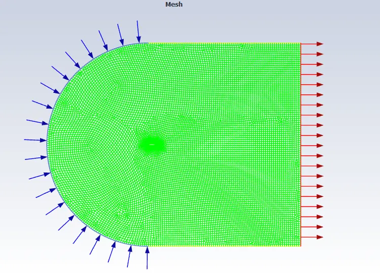
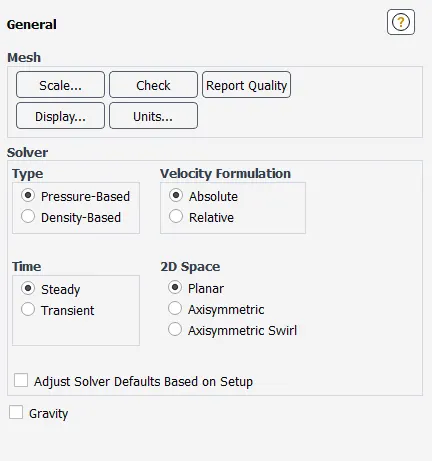
2. Pressure-based, steady solver.
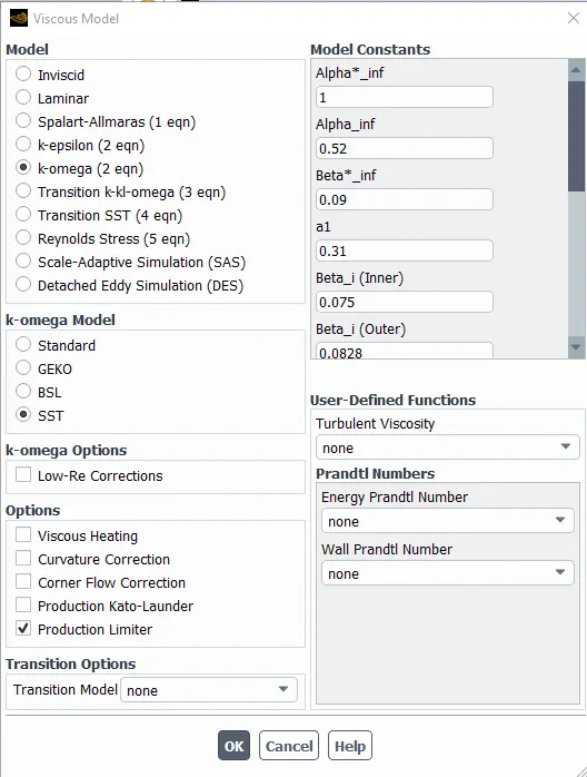
3. k-omega, SST model.
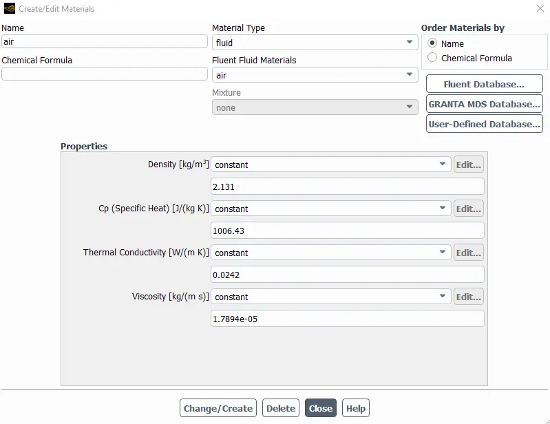
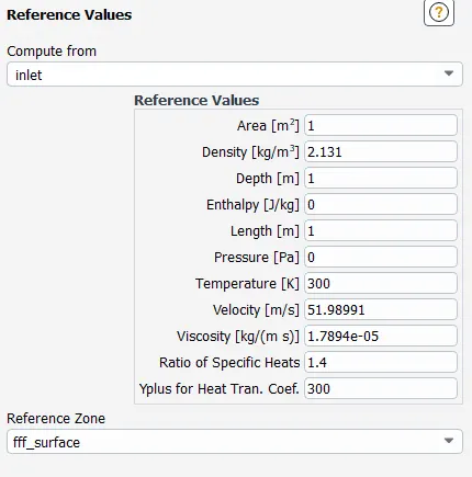
4. Fluid-Air with 2.131 kg/m3 Density.
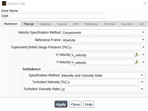
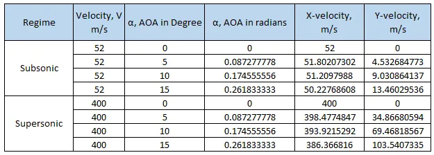
5. Inlet, Components in Velocity speci. method. X-velocity and Y-Velocity as a parameter sets for subsonic & supersonic flow regime.
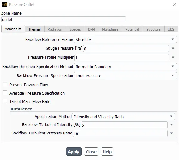
6. Outlet as pressure based.
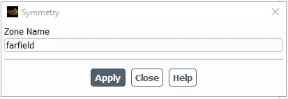
7. Symmetry for the faifield domain.
8. Reference values, Compute from Inlet.
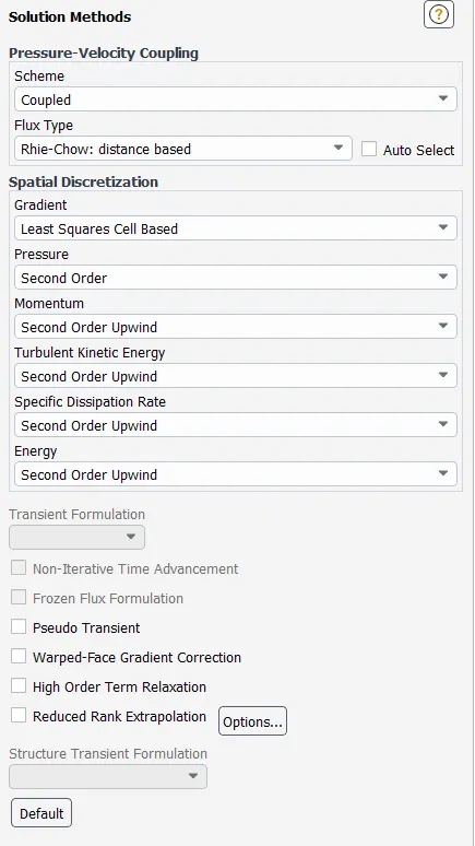
9. Solution method as coupled.
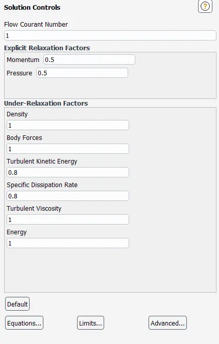
10. Solution controls for flow courant number as 1.
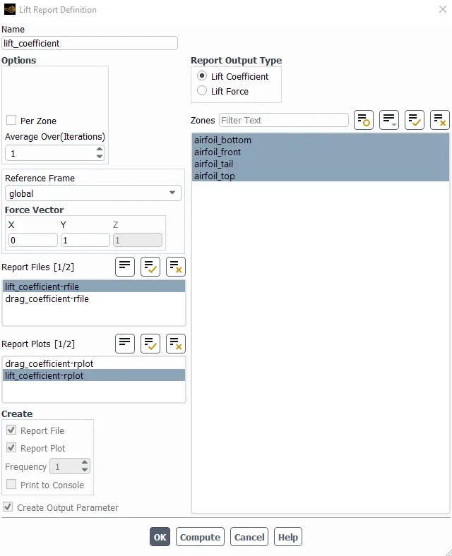
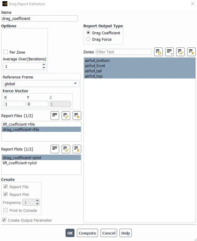
11. Lift and drag coefficient for airfoil walls.
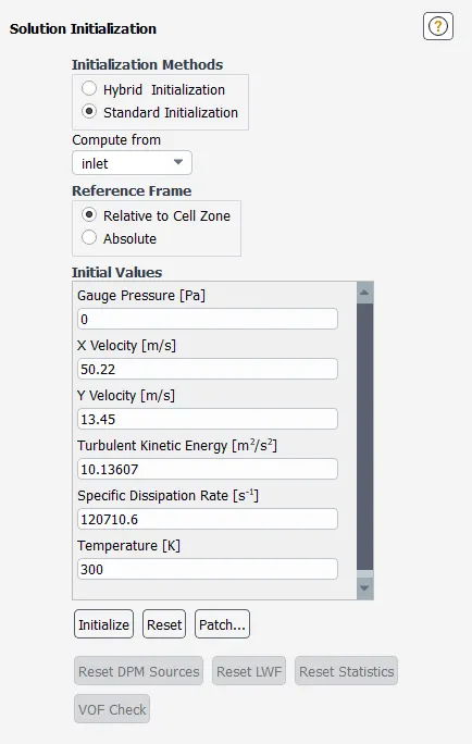
12. Solution Initialization as standard amd compute from Inlet.
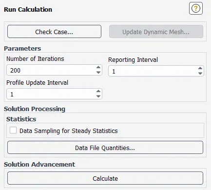
13. Run calculations with 200 number of iterations.
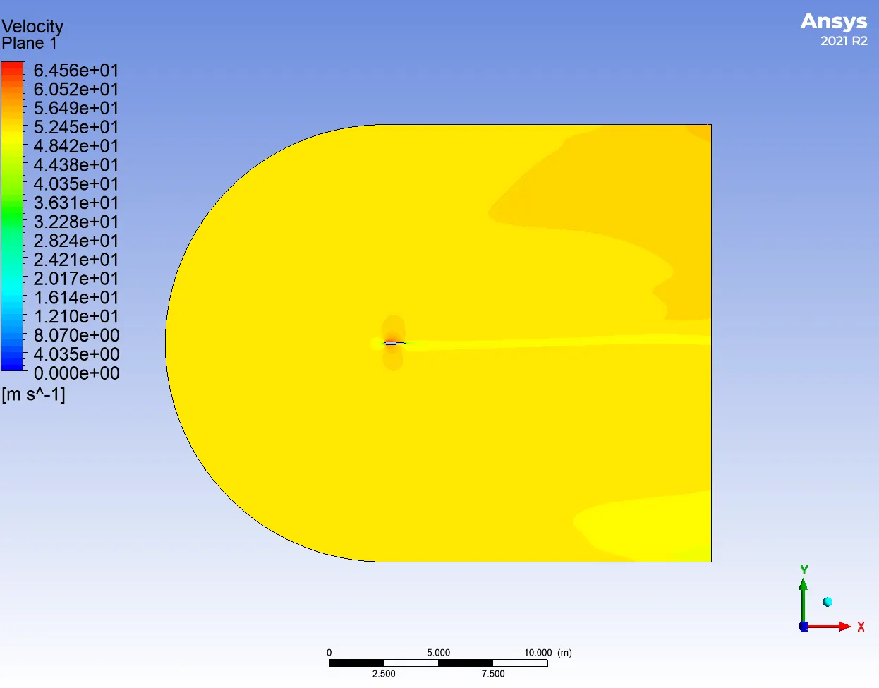
Results: Case-1: Subsonic regimes.
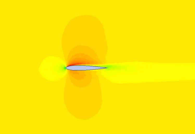
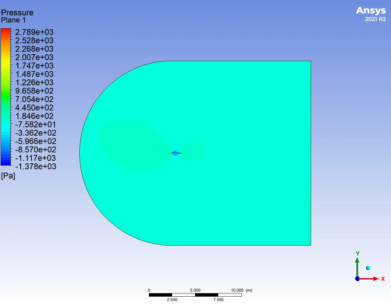
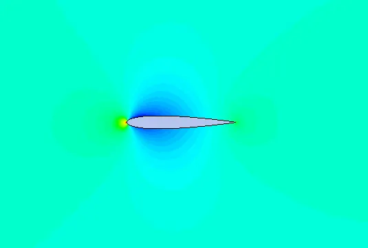
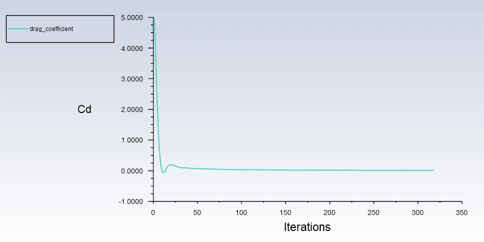
1. Case-1: 0º AOA
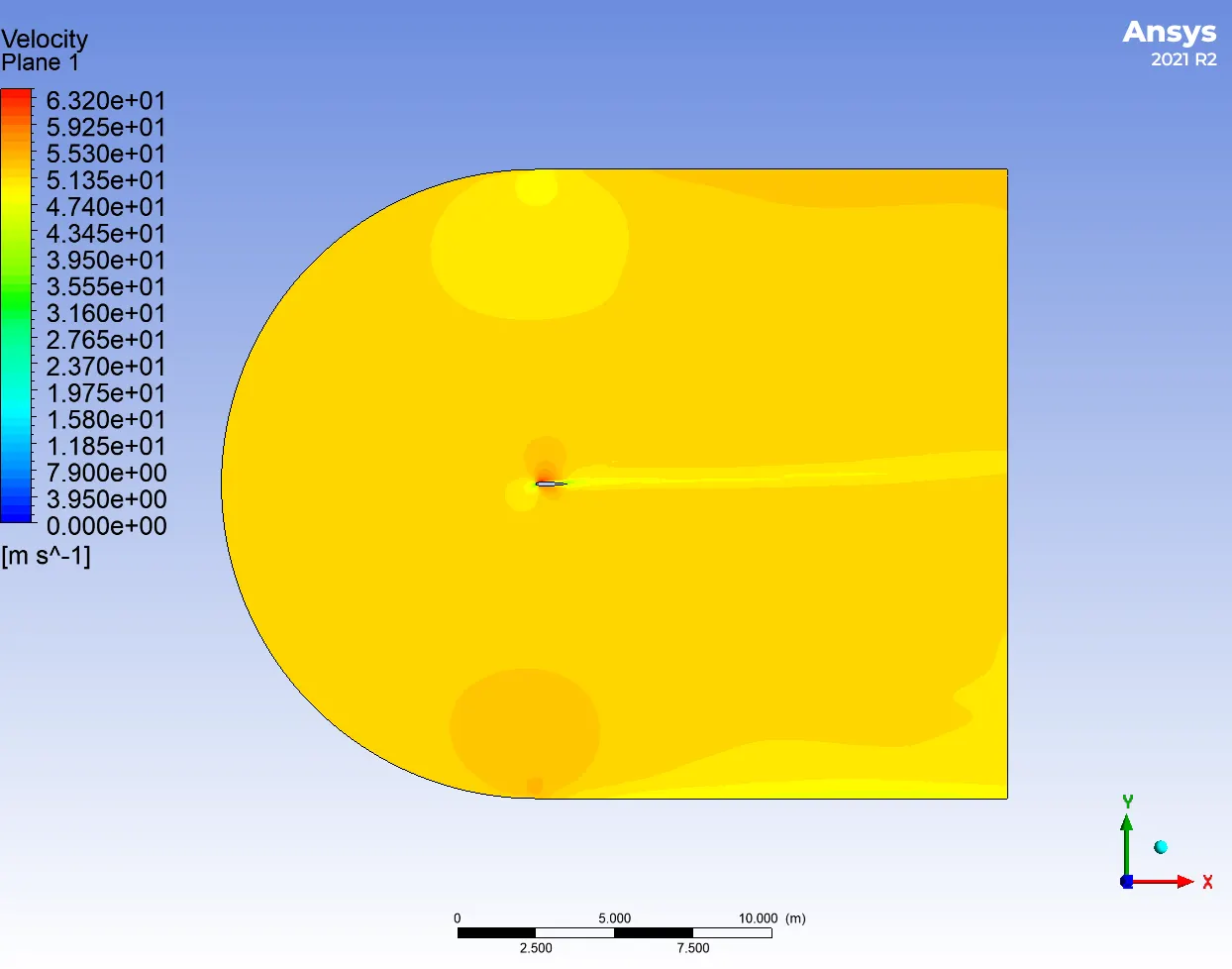
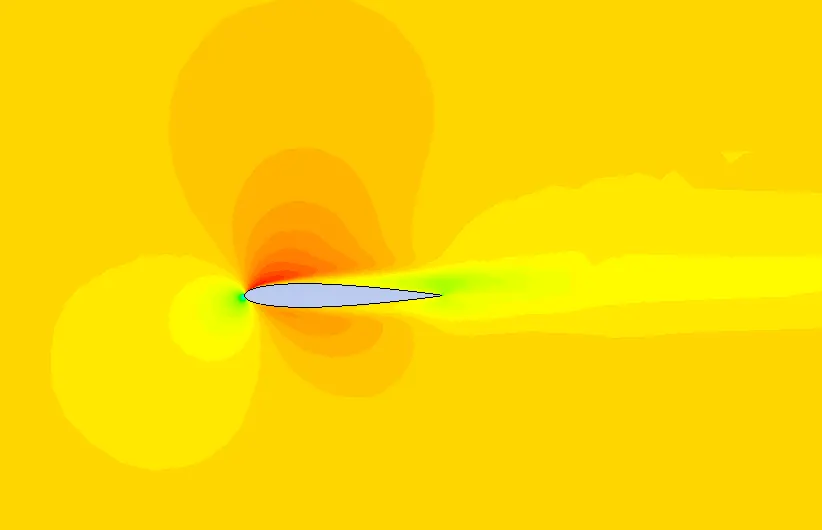
Velocity contour
Pressure contour
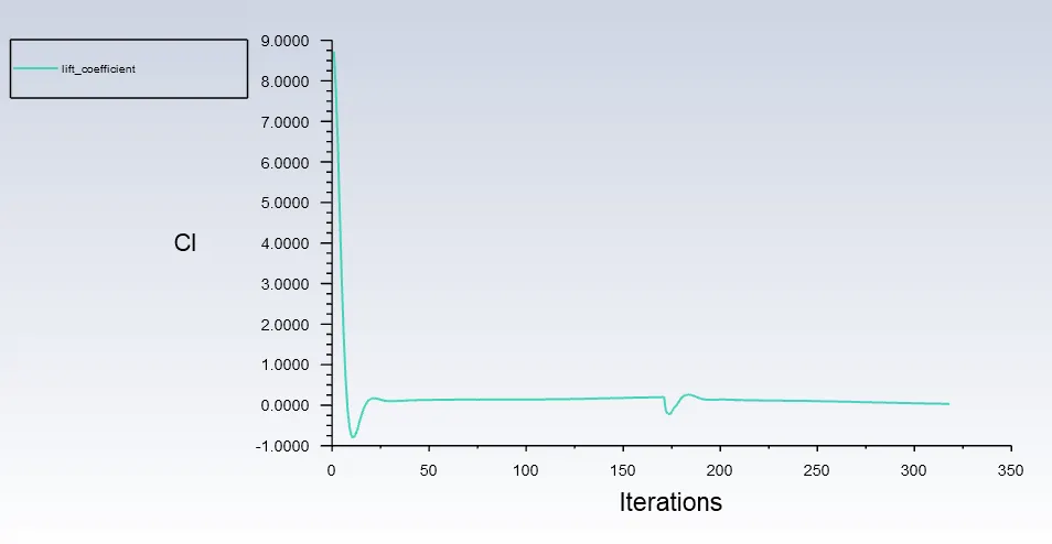
Lift and Drag coefficients plots
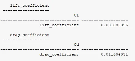
Lift and Drag coefficients values
2. Case-1: 5º AOA
Velocity contour
Pressure contour
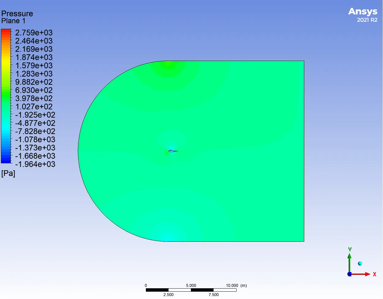
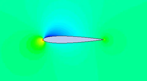
Lift and Drag coefficients plots
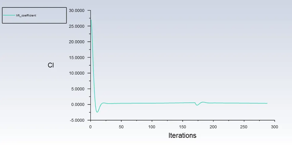
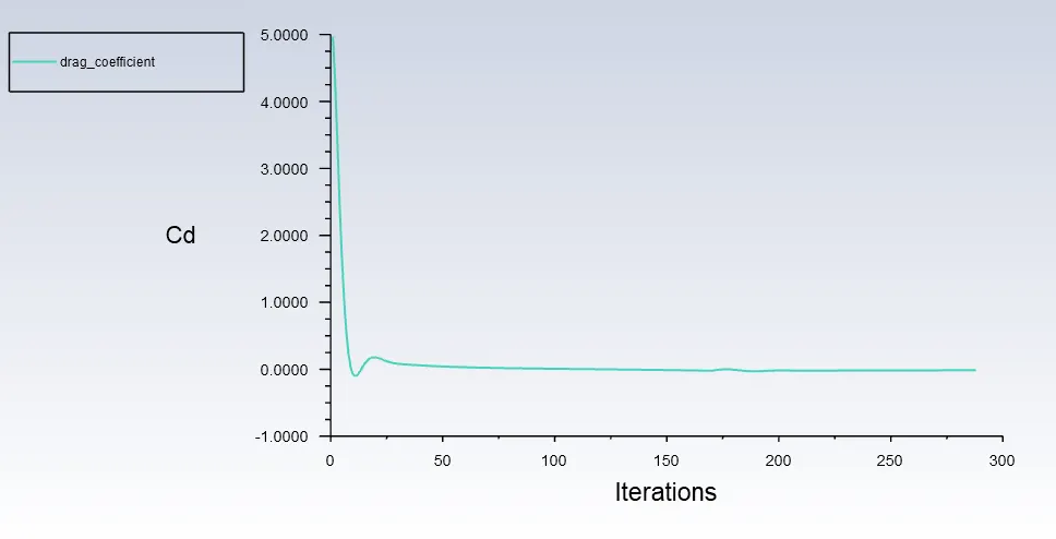
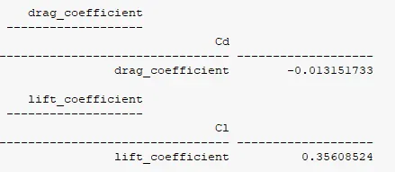
Lift and Drag coefficients values
3. Case-1: 10º AOA
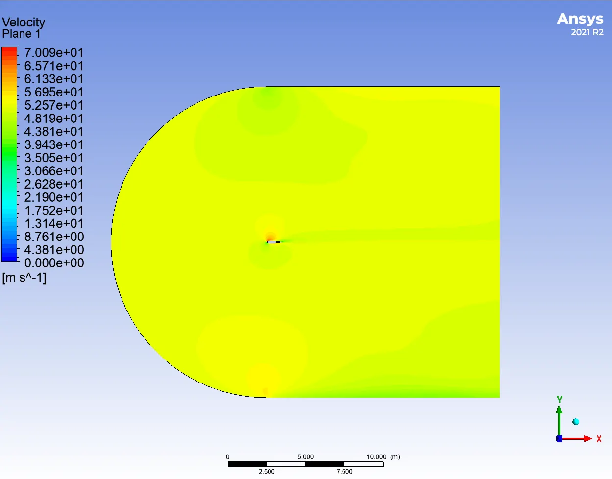
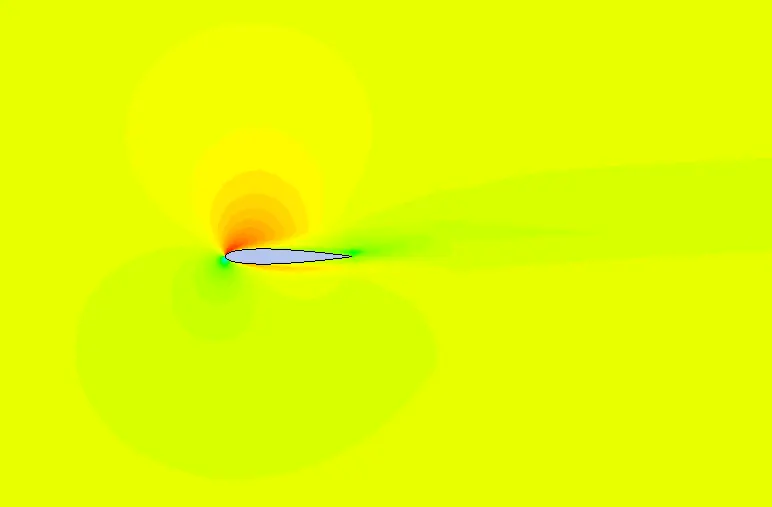
Velocity contour
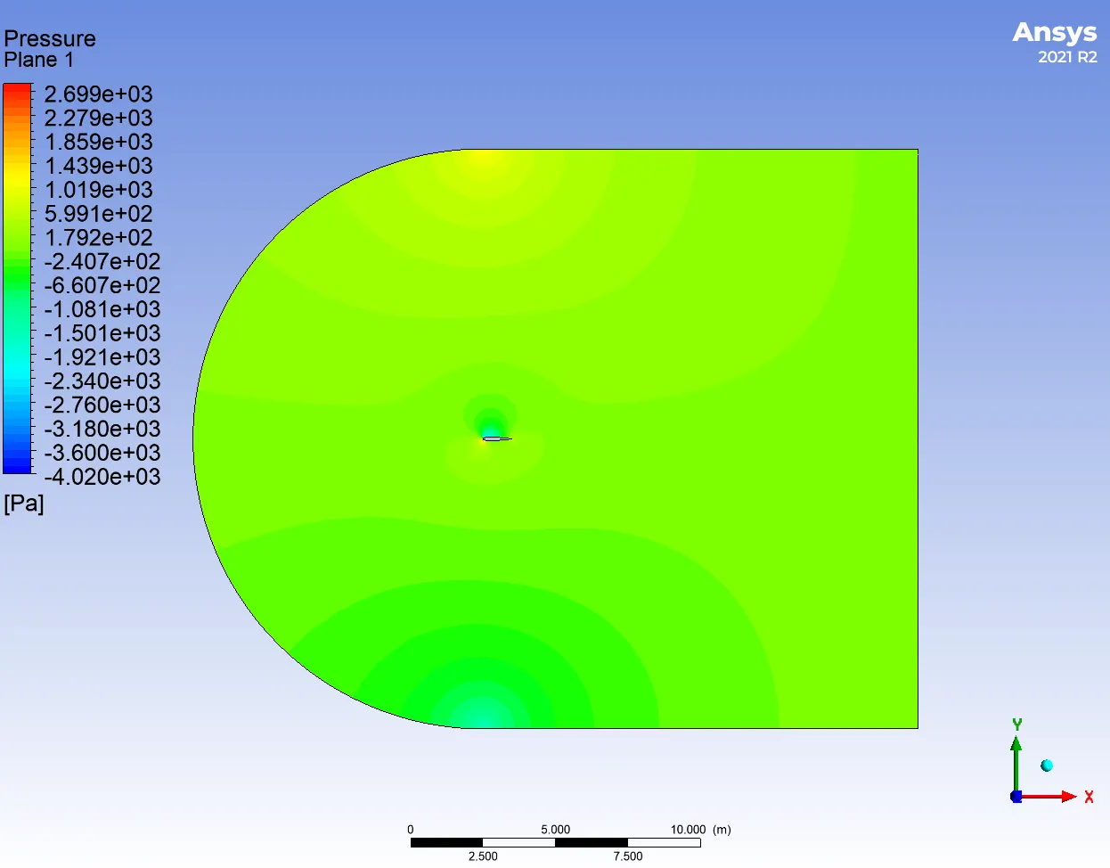
Pressure contour
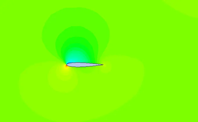
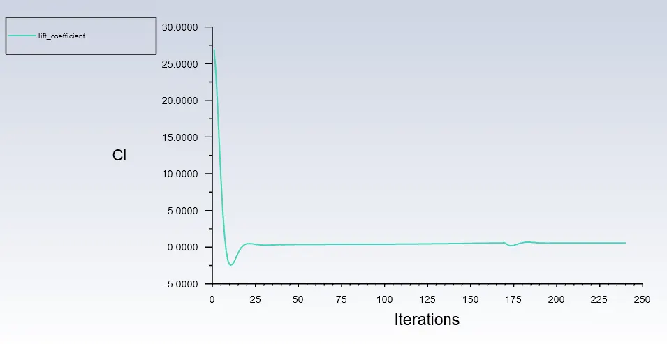
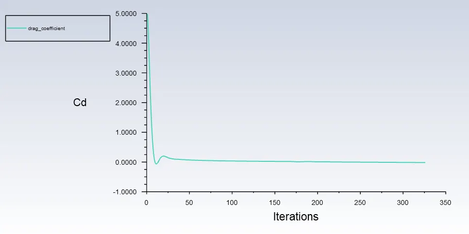
Lift and Drag coefficients plots
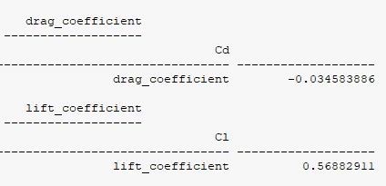
Lift and Drag coefficients values
4. Case-1: 15º AOA
Velocity contour
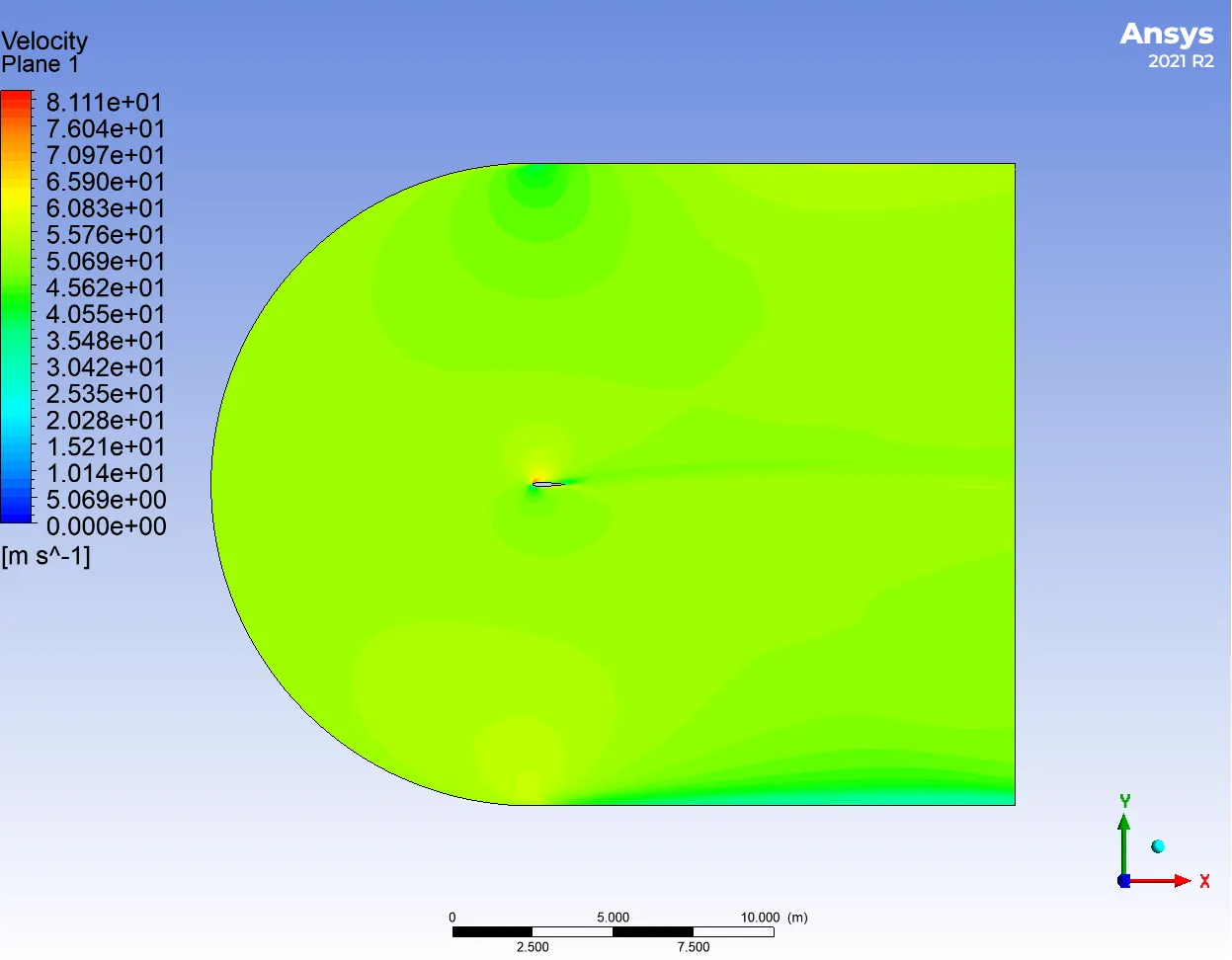
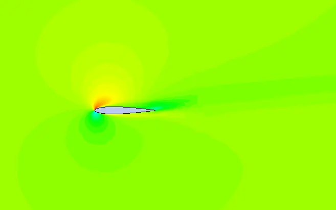
Pressure contour
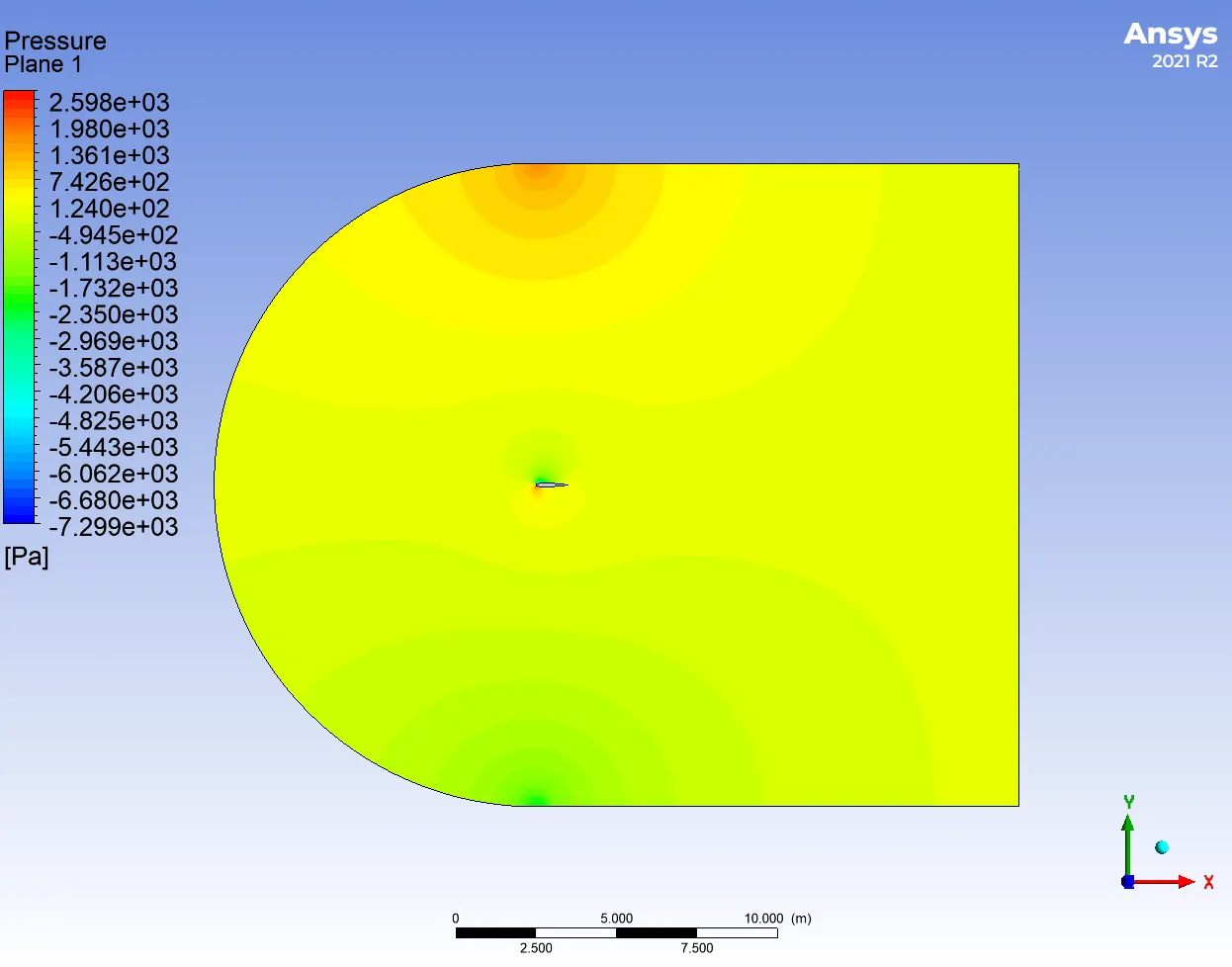
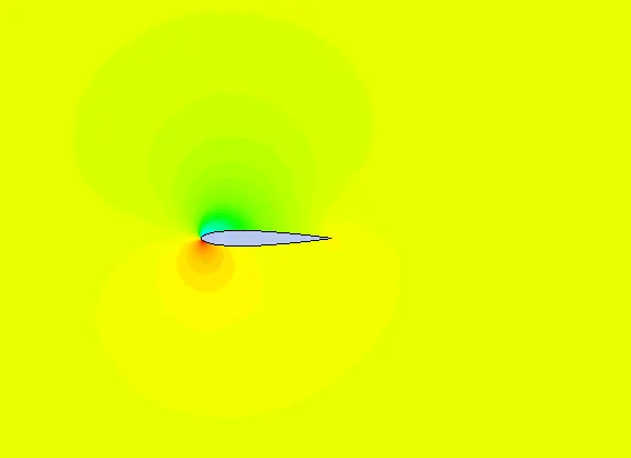
Lift and Drag coefficients plots
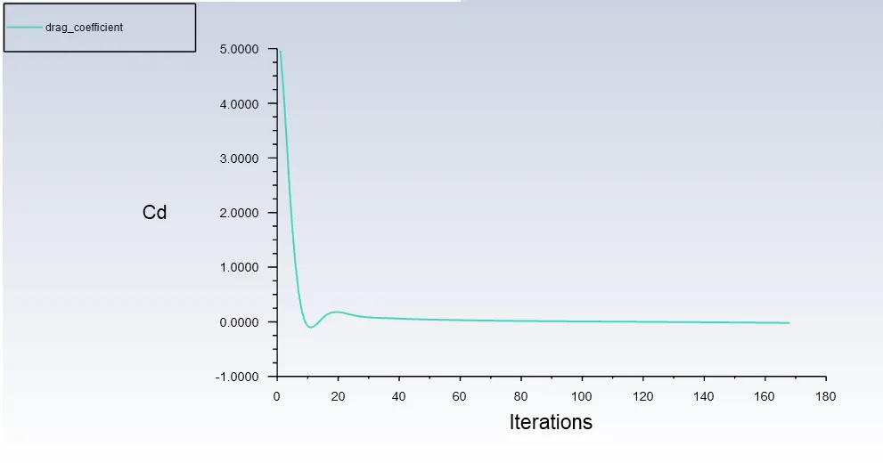
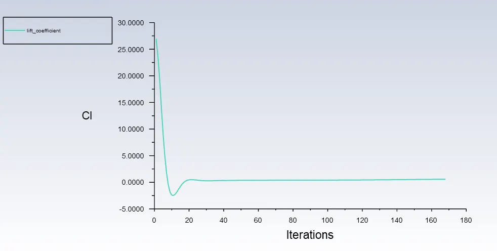
Lift and Drag coefficients values
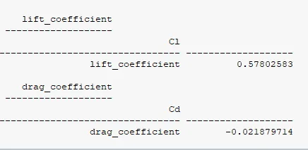
Case-2: Supersonic regimes.
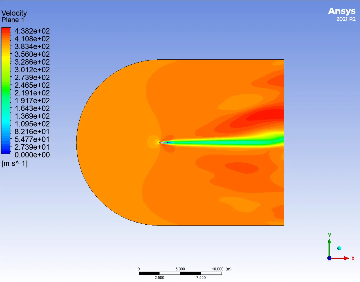
4. Case-2: 0º AOA
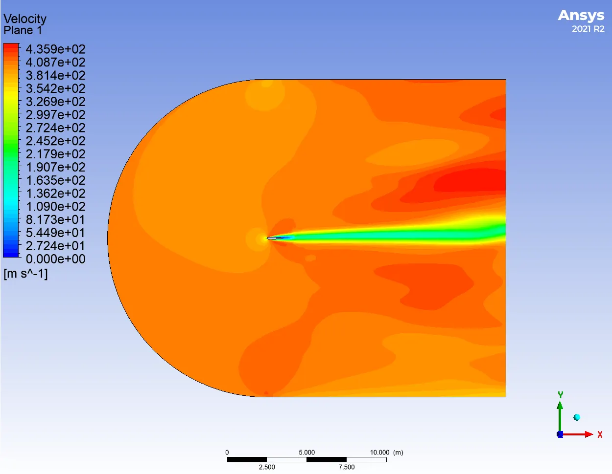
Velocity contour
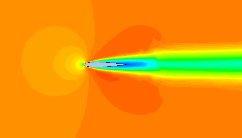
Pressure contour
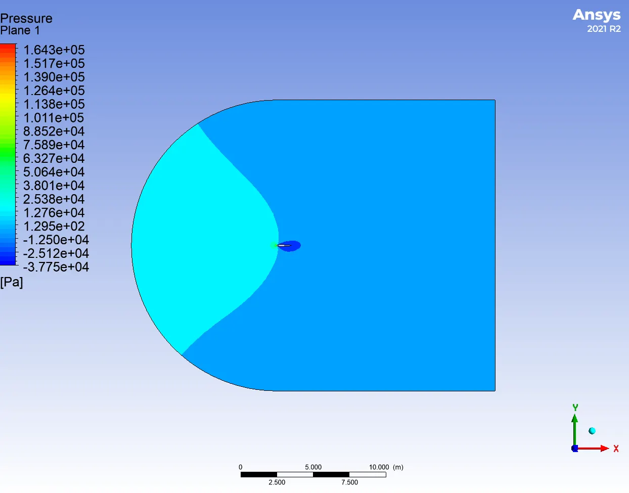
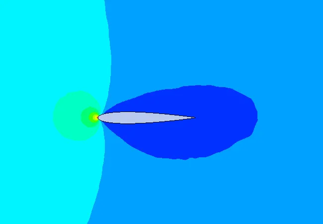
Lift and Drag coefficients plots
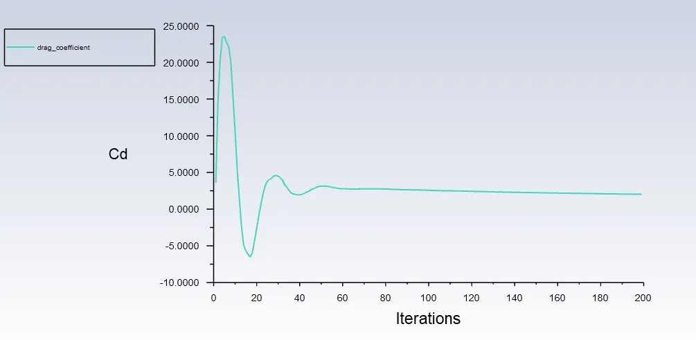
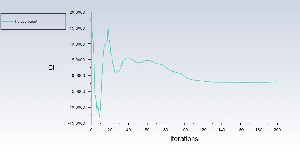
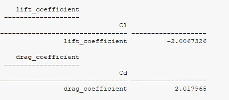
Lift and Drag coefficients values
4. Case-2: 5º AOA
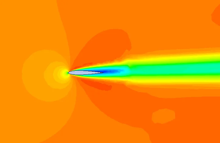
Velocity contour
Pressure contour
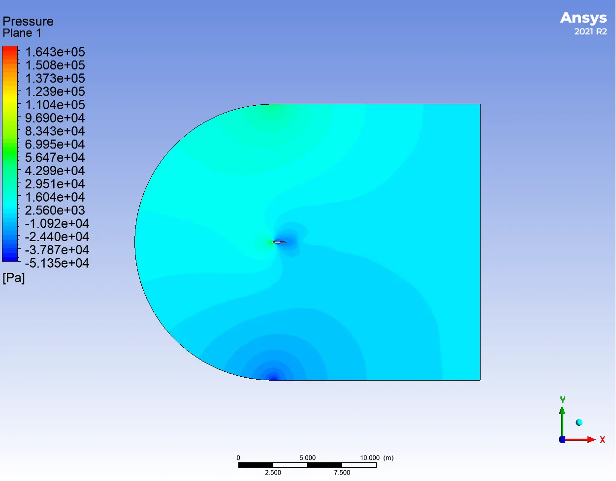
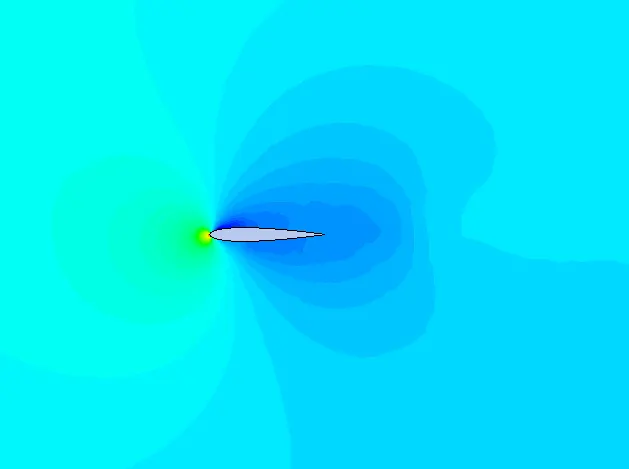
Lift and Drag coefficients plots
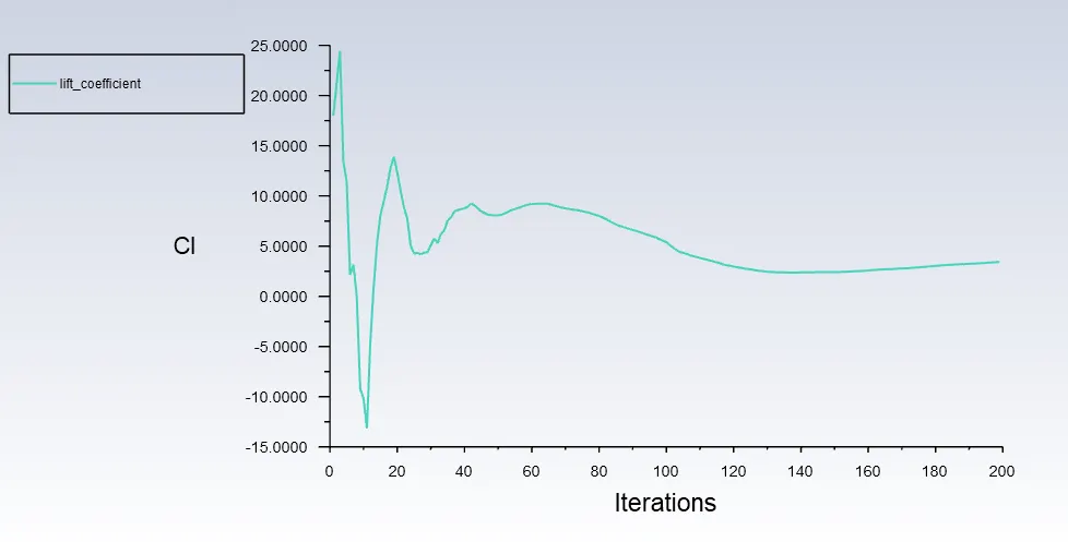
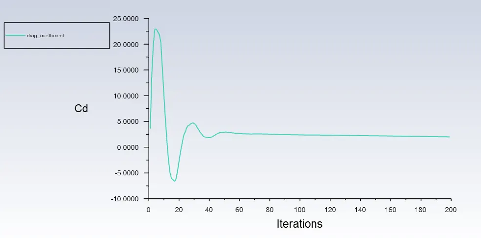
Lift and Drag coefficients values
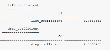
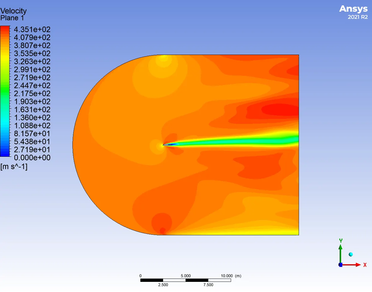
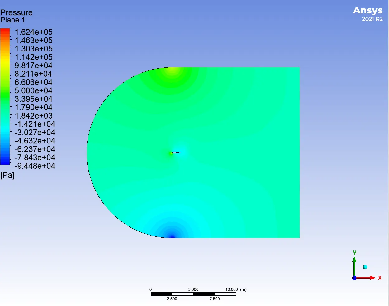
4. Case-2: 10º AOA
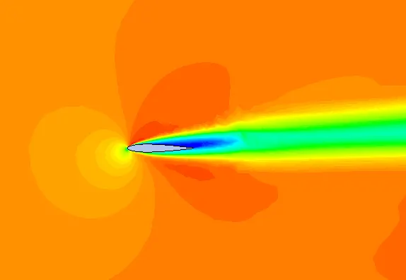
Velocity contour
Pressure contour
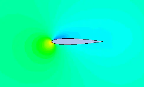
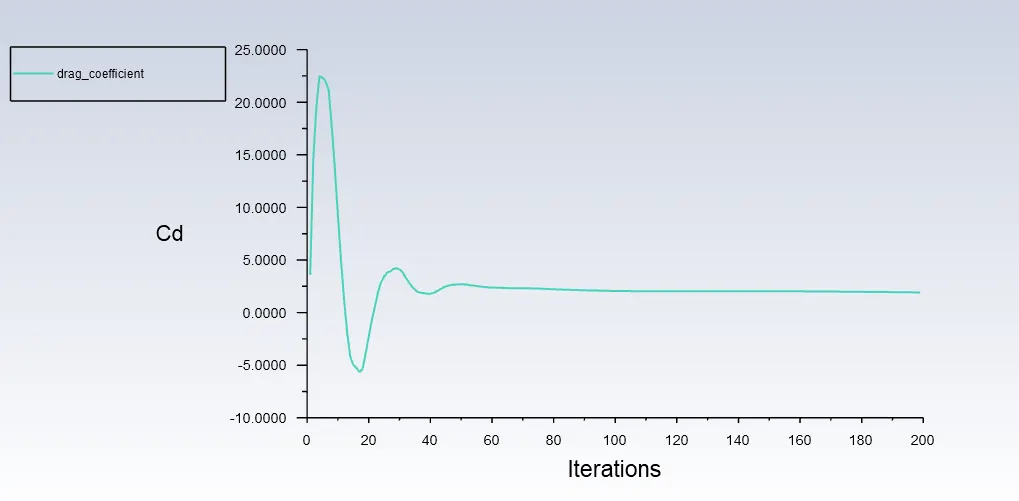
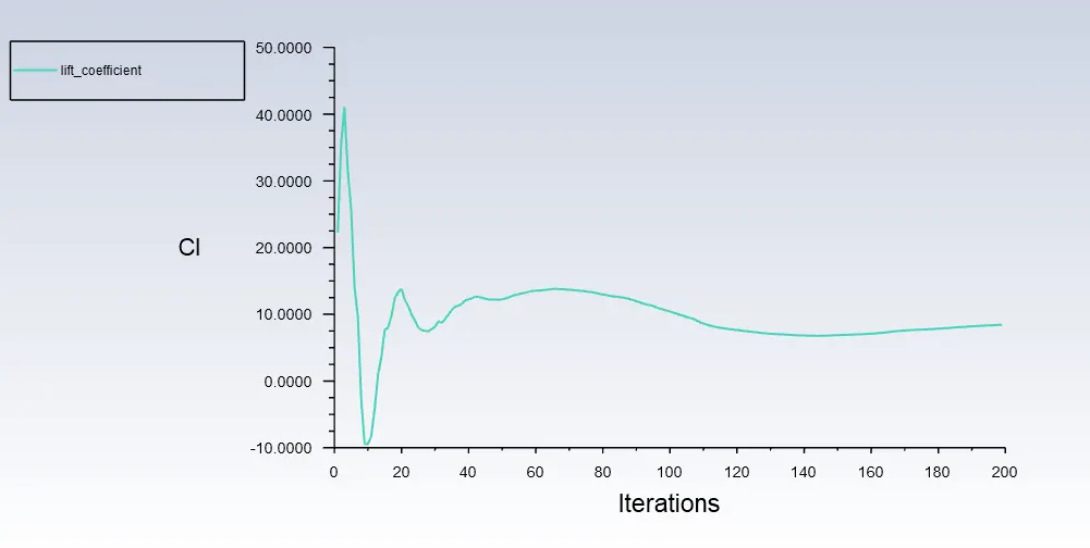
Lift and Drag coefficients plots
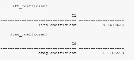
Lift and Drag coefficients values
4. Case-2: 15º AOA
Velocity contour
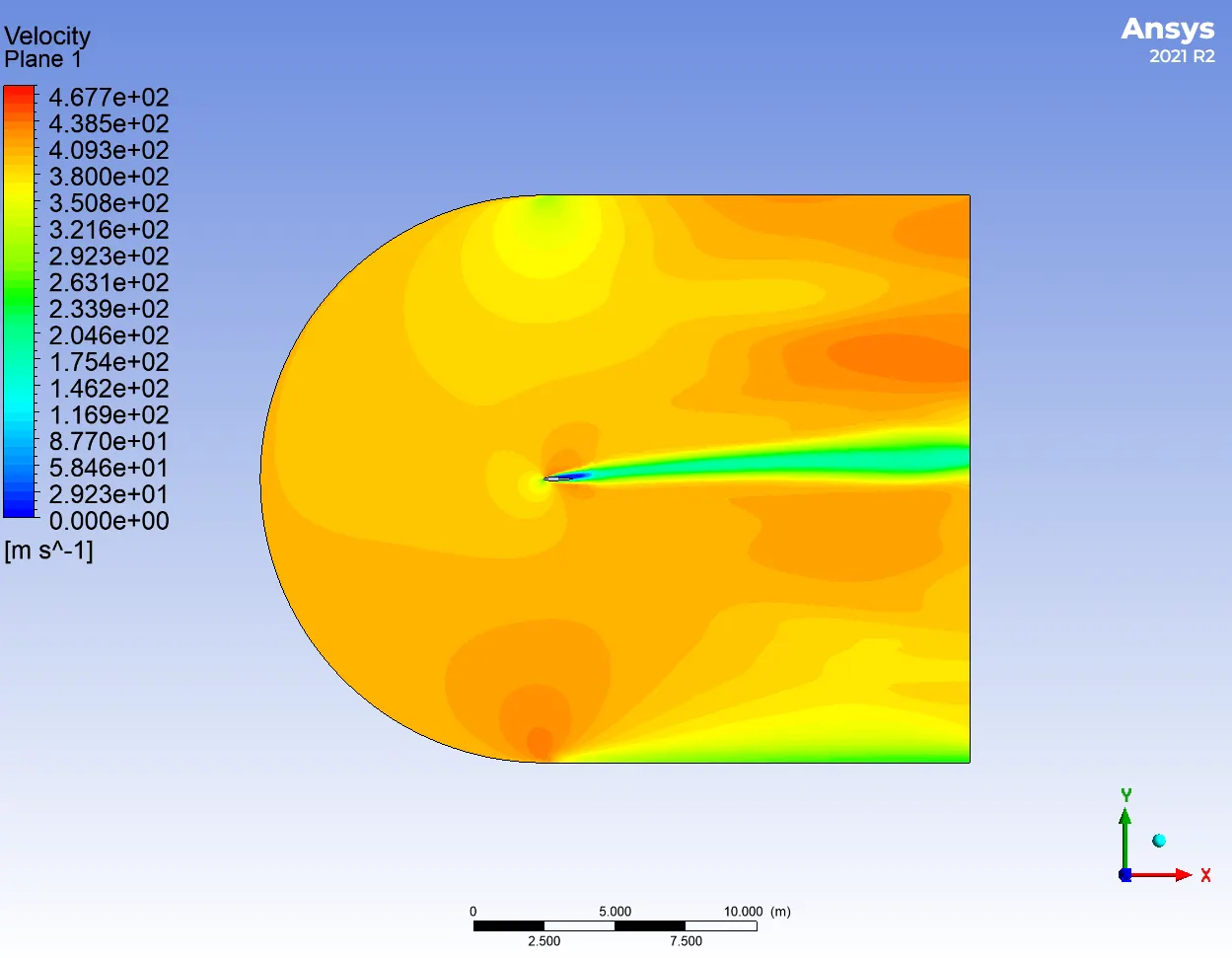
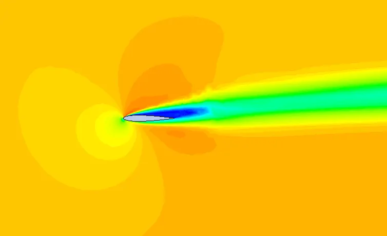
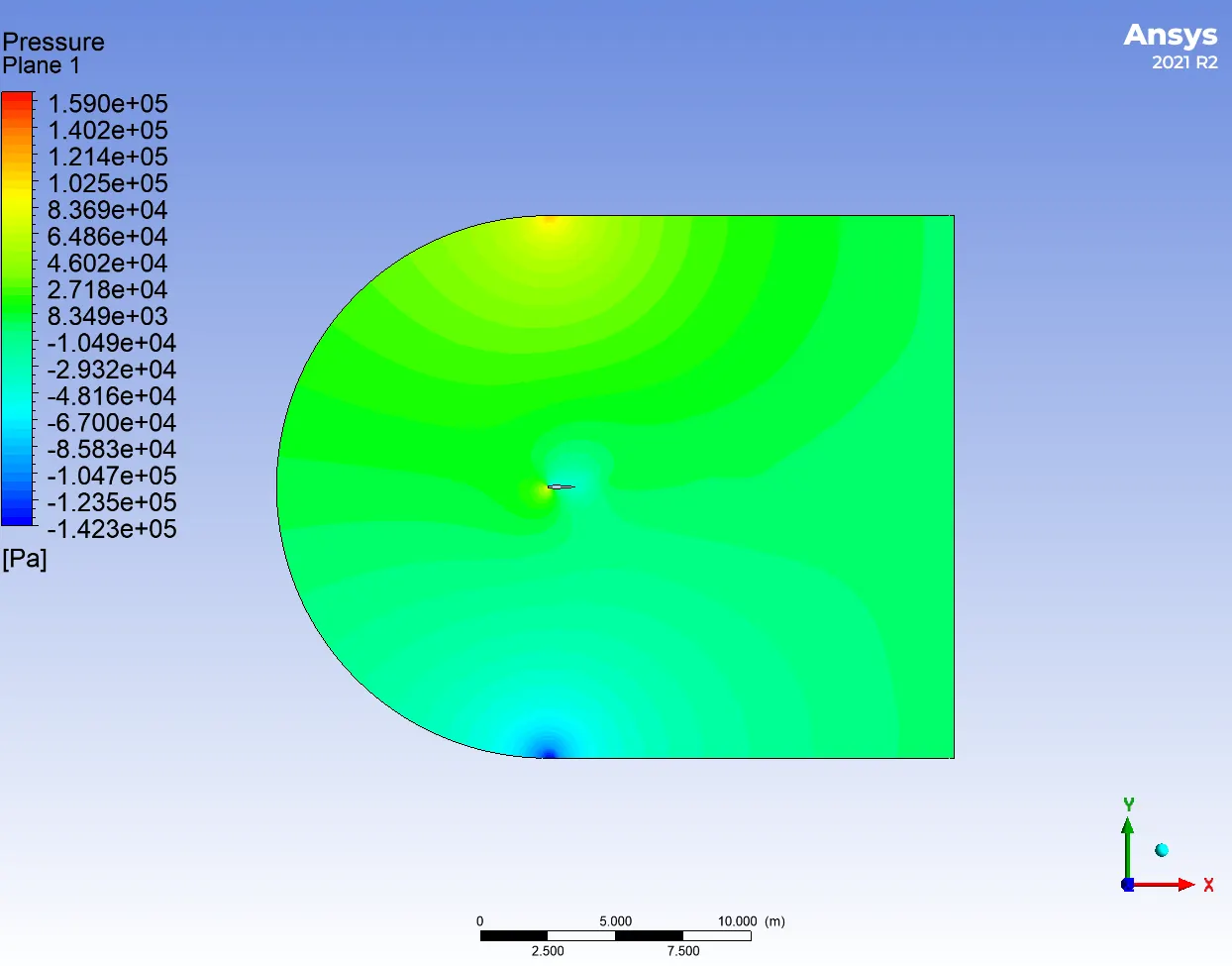
Pressure contour

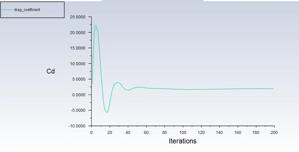
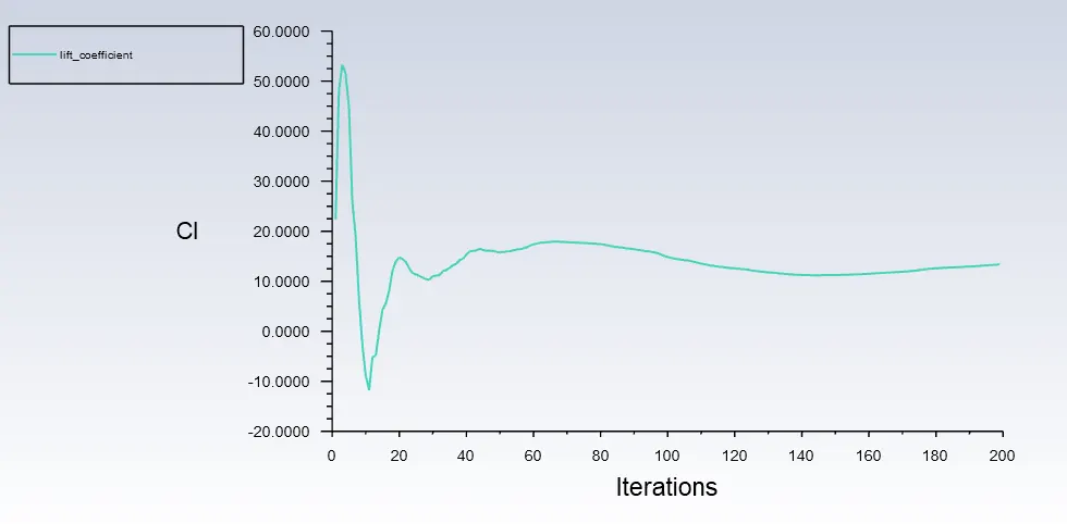
Lift and Drag coefficients plots
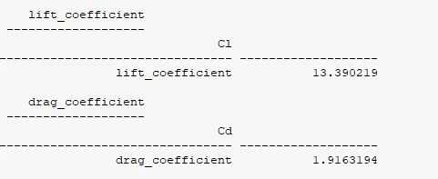
Lift and Drag coefficients values
Conclusion:
1. For different angle of attack, the simulation was carried out in Ansys fluent.
2. Lift and drag coefficient for subsonic and supersonuic regime were compared. Stagnation points were appered at airfoil tip.
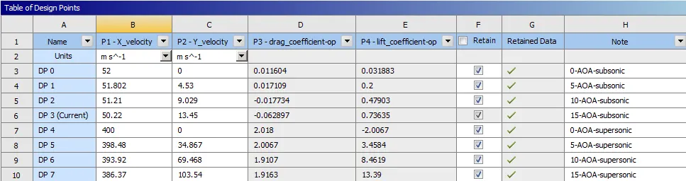
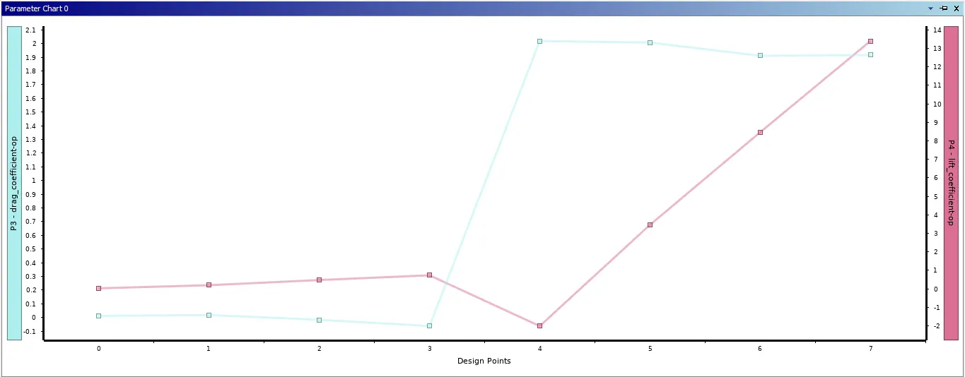
3. From the above graph, we can conclude as in subsonic regime, Lift coefficient is more then the drag coefficient. In supersonic regime, Lift coefficient is more then the drag coefficient.
References:
2. Airfoil (NACA 0012) Tutorial - SimFlow CFD Software (sim-flow.com)
3. Validating fundamentals: 2D NACA 0012 Airfoil Validation - Femto Engineering - Femto Engineering