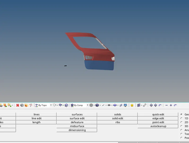
Week 7- Meshing of Backdoor Challenge
OBJECTIVE : Mesh the given back door panel of a car with given element size and satisfied quality criteria.
PROCEDURE :
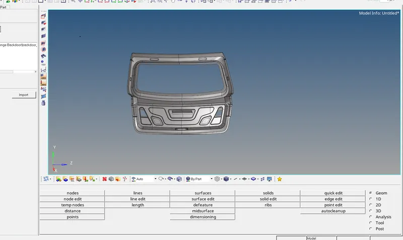
- This is the cad model of backdoor panel of car showed in the image.
- This part is consist of 3 parts, which we have to separate first.
- After separation of parts we can observe that they are all symmetrical.
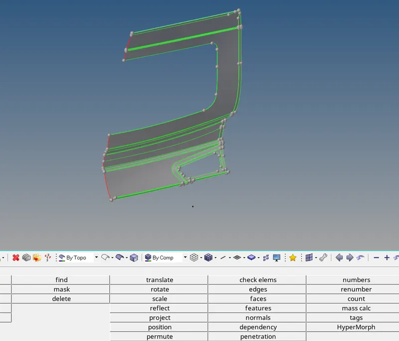
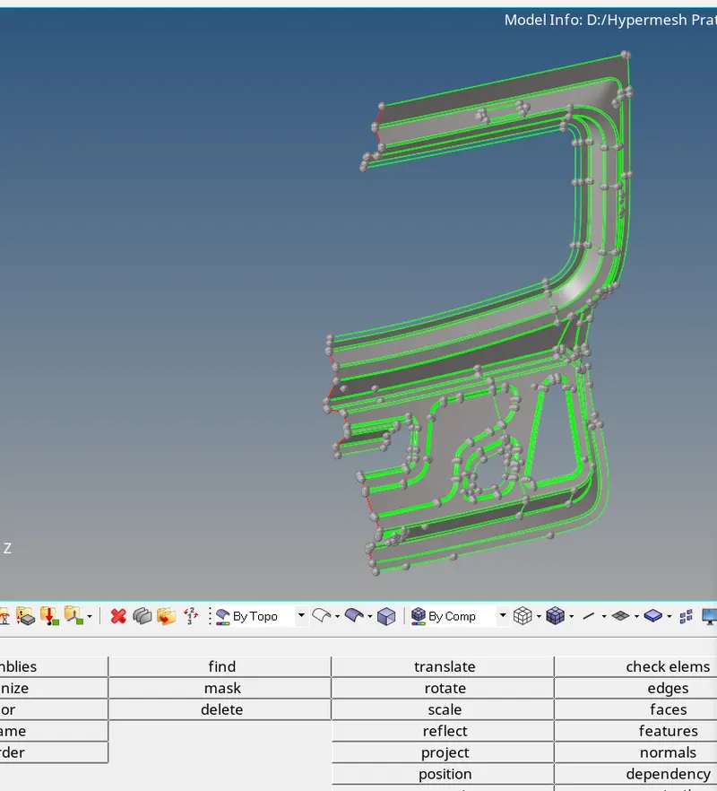
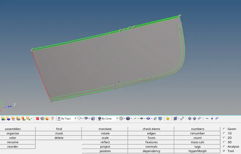
- So, here in this images one can observe that have we have separated each part from parent geometry.
- Because parent geometry in too complicated and will take a lot of time to extract the mid surface and mesh it.
- So, the sole purpose of separating them was to save some time.
- Delete half surfaces exactly from middle and mesh them.
- After meshing reflect the elements so that it resembles the whole part.
- Separate this parts by creating a part id for each part.
- I divided this parts as center part, middle part and outer part.
- Go by each part, extract mid for each part, mesh each part separately.
- After extraction of mid surface it was observed that the part is disturbed, there are unwanted feature lines which will result in bad mesh flow and at few areas will fail for quality as well.
- So, in order to have a proper mesh flow and good quality mesh, toggle required lines.
- In order to have best mesh flow and good quality of mesh, the mid surface should be perfect. For that we need to work on it properly.
- There were few fillets whose radius was very small and it might have failed in quality if we should have tried to capture the surface propery.
- Thus there we modified the surface.
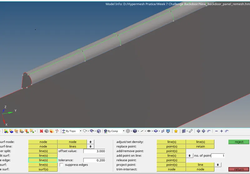
- In this image we can see that we have a fillet and this will definately going to fail for quality.
- So, we tried to modify the geometry littel bit by drawing a line in the center of boundary lines of the fillet.
- And after we get a proper line then toggle the boundary lines of the fillet.
- Also, there were few areas of the geometry where the mesh can not be adjusted without failing for quality parameters due to its design.
- Thus, we have to accept this failed quality of the mesh in order to capture the surface appropriately.
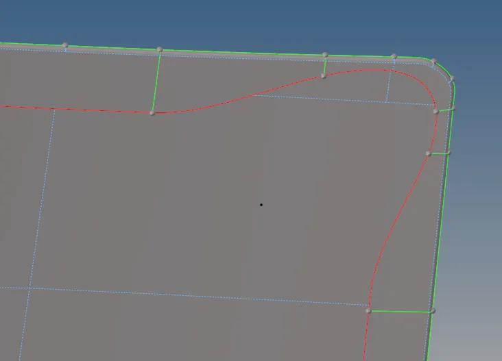
- In this image we can clearly see the shape of geometry which is intricate.
- So, in such cases we have to accept failed quality of mesh.
- Again, there were few case, in which the lines were attached to each other.
- So, use toggle command to separate them.
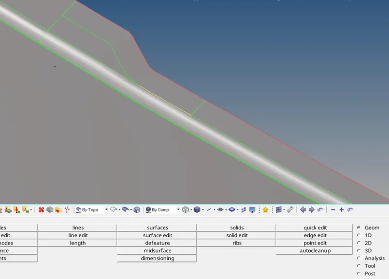
- In this image we can see the yellow line which points out there are three surfaces which are attached to a single edge.
- With the use of toggle command we can get rid of it.
- After meshing each part individually perform various checks like normal check, dependency check, penetration check, check for any free edges.
- Now, the last thing is to assign thickness to model.
- For that create material ID, propertry for each part created and assign the property to each part along with material.
- In the property section provide the thickness of model and at last assign that property to respective part.