Week 7-Long Piston With Cam
LONG PISTON AND CAM
AIM:
To simulate and analysis for the given 3 cases for the long piston and cam challenge.
MODEL:
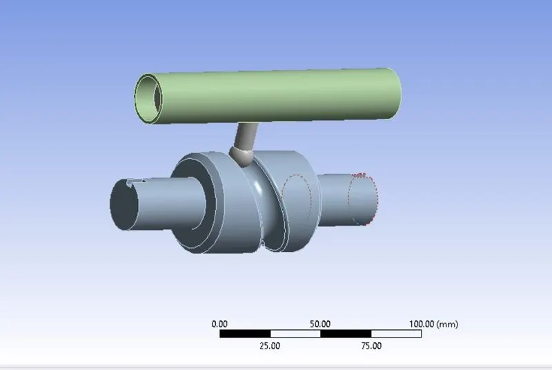
The given model consists of barrel and barrel cam followed by a cam follower.
MATERIAL:
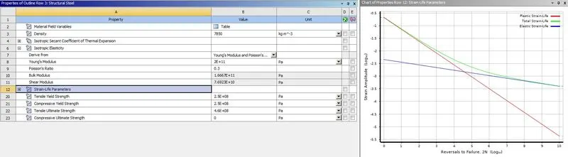
The model is imposed with the structural steel as the material with equal stiffness to all the parts in the model.
CONNECTIONS:
CONTACTS:
Two contacts have been detected in the model. One Is with the barrel cam and the follower and the second contact is with the piston and the barrel. according to the given three cases, we have to assign the type of contact to the model as 1) frictionless 2) frictional contact with co-efficient as 0.1 and finally frictional contact with the co-efficient of friction as 0.2.

JOINTS:
Three types of joints have been provided to the model to support the simulation.
- Fixed joint
- Revolute joint
- Translational joint
Fixed joint:
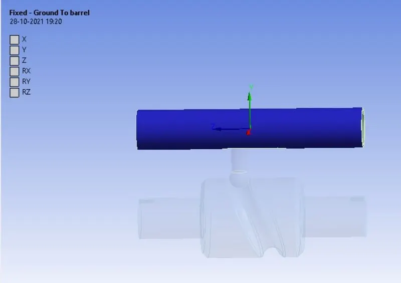
The fixed joint has to be provided to the barrel since the motion has been transferred from the barrel cam to the follower and to the piston, where the piston is made to be in contact with the barrel, if the piston moves the barrel also moves, the type of joint used here is body to ground, since there is no reference to fix the barrel by means of another body.
Revolute joint:
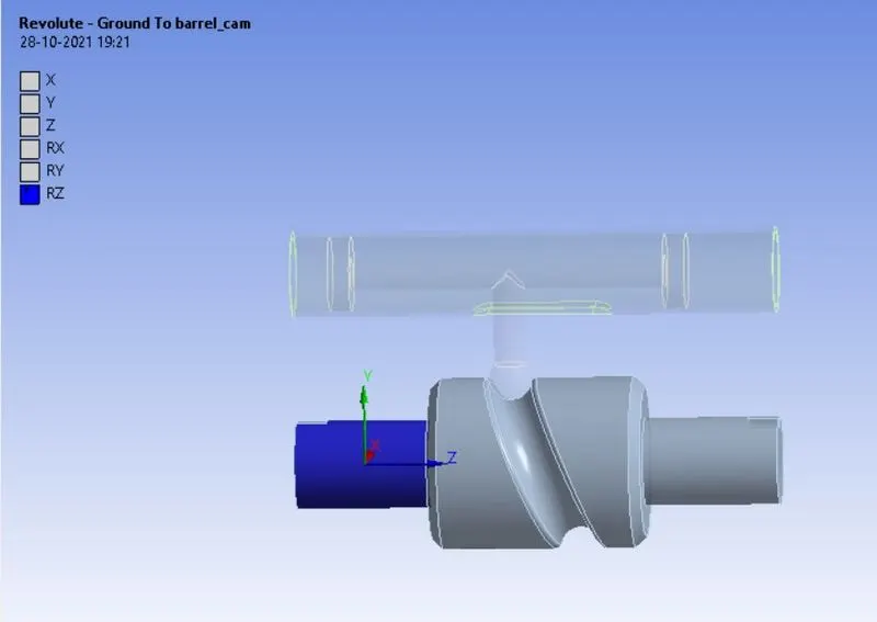
The rotational force Is the master force to run the simulation, in order to provide the rotational force, we have to assign the revolute joint to the cam , the type of joint used here is also body to ground.
Translational joint:
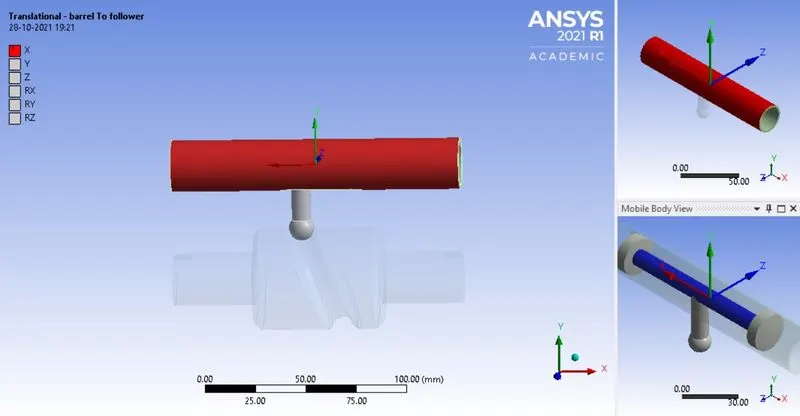
The rotational force from the cam is transferred to the piston through the follower, as a result of this transfer the piston translates, to guide the translational force we are assigning the translational joint to support the motion. The type of joint used here is body to body joint, here the piston translates along the barrel. The mobile scope of the model is piston and the reference has to be given as barrel, since the barrel guides the piston to translate along.
MESH:
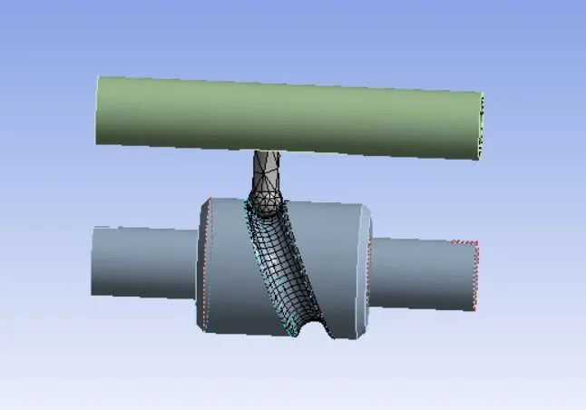
The mesh has been created on the basis of grid dependency test and the face meshing of size of 3 mm of the faces of the follower and the barrel cam where the contacts had been made. Grid dependency test is applicable only to the piston and the other face of the follower.
ANALYSIS SETTINGS:
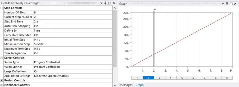
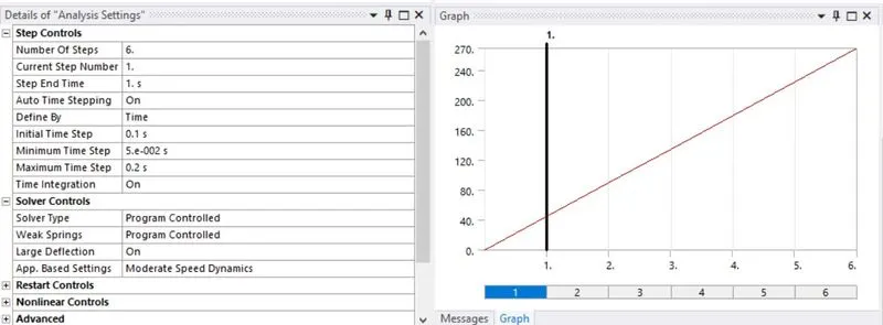
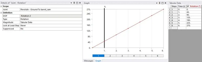
The simulation has been set up to 9 steps for the case 1 and case 2 meanwhile for case 3 it has set up to 6 steps. the solver type has been set to program controlled as well as the weak springs. In the non-linear controls the energy stabilization ratio has been set to 0.1 as constant.
CASE 3 : FRICTIONAL CONTACT WITH CO-EFFICIENT OF FRICTION AS 0.2
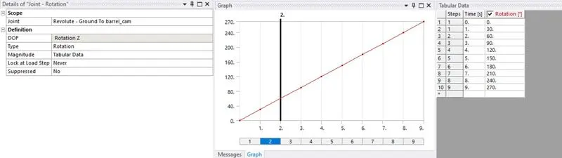
Joint load:
The revolute joint load has been imposed as the following for the first 2 cases, while for the third case rotation has been made to 45 degree per step up to 270 degree.
CASE 3 : FRICITIONAL CONTACT WITH CO-EFFICIENT OF FRICITON AS 0.2
Case 1: frictionless contact
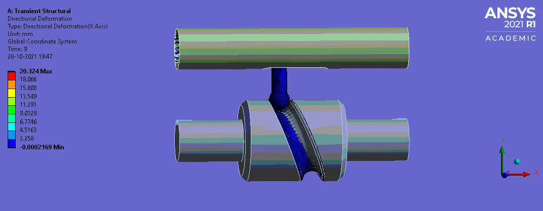
Directional deformation:
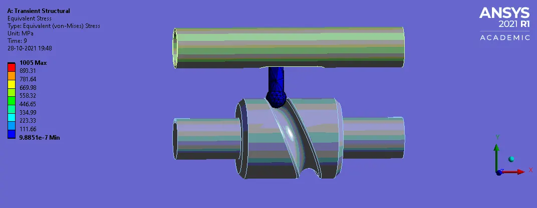
Equivalent stress:
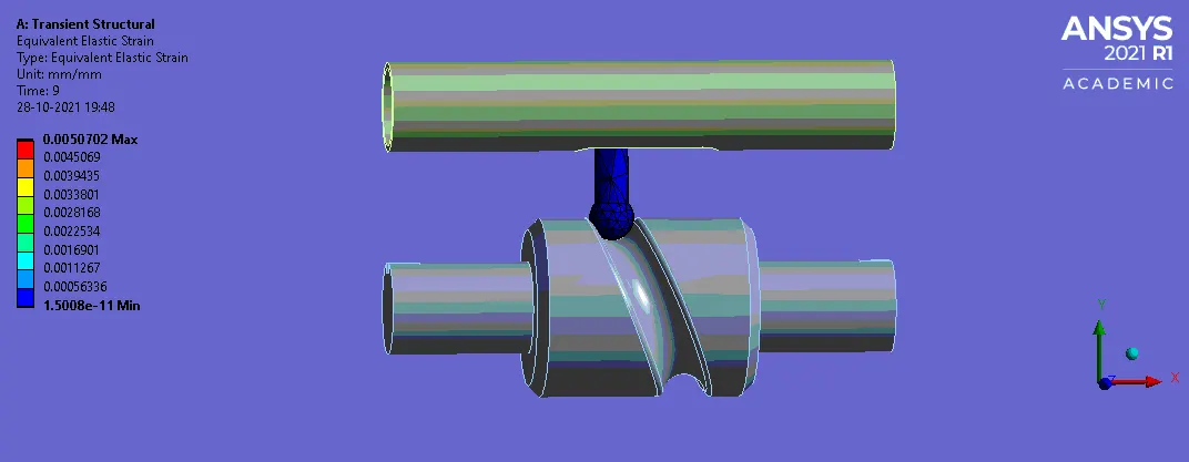
Equivalent elastic strain:
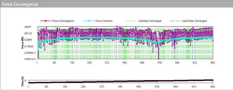
FORCE CONVERGENCE :
FROM THE ABOVE SIMULATION ON CASE 1 , WE INFER THAT THE STRESS GENERATED ON THE MODEL IS 1005 MPa ,
Case 2: frictional contact with frictional co-efficient as 0.1
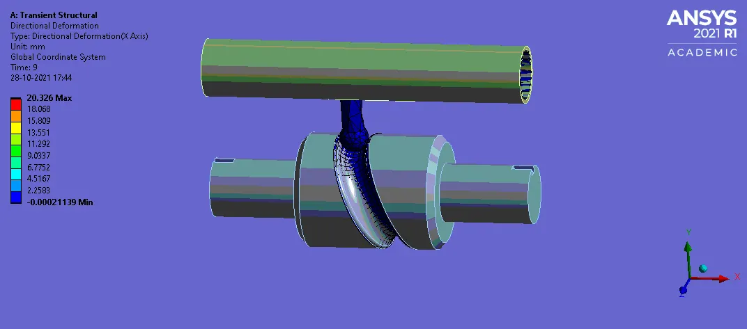
Directional deformation:
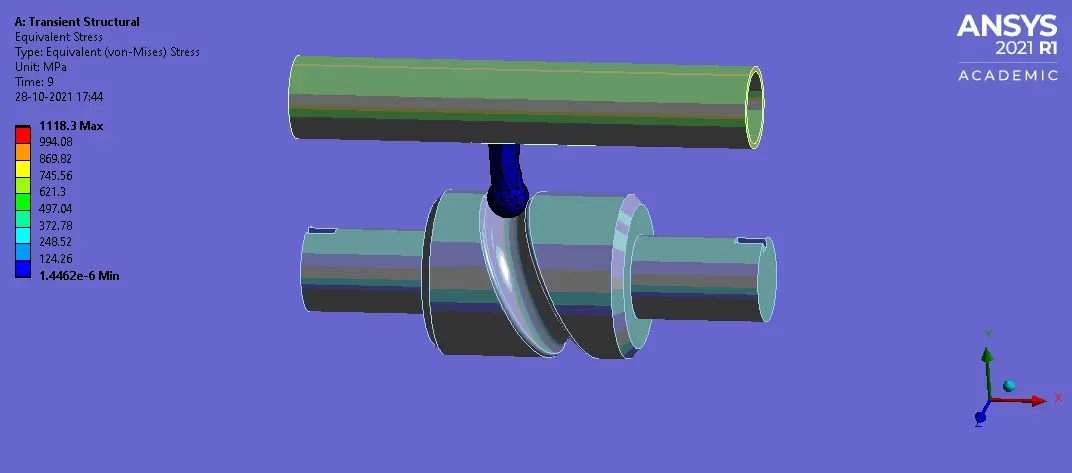
Equivalent stress:
Equivalent elastic strain:
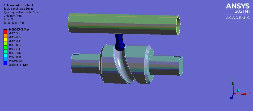
FORCE CONVERGENCE :
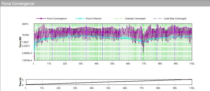
HERE FROM THE ABOVE SIMULATION WE INFER THAT THE STRESS GENERATED ON THE MODEL IS 1118.3 MPa .
Case 3: frictional contact with co-efficient of friction as 0.2
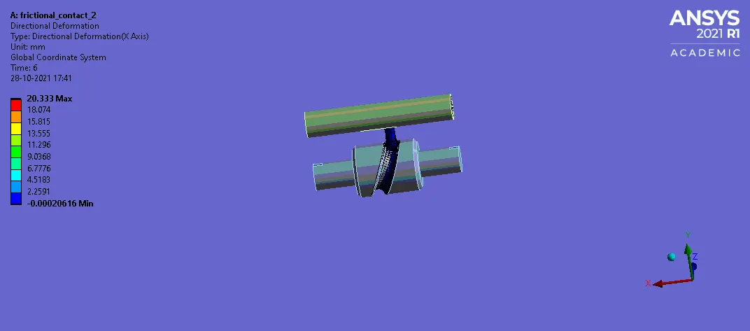
Directional deformation:
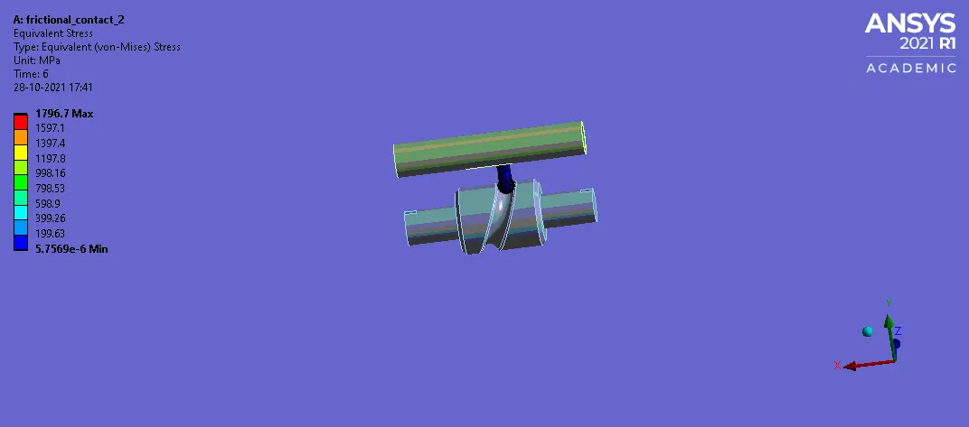
Equivalent stress:
Equivalent elastic strain:
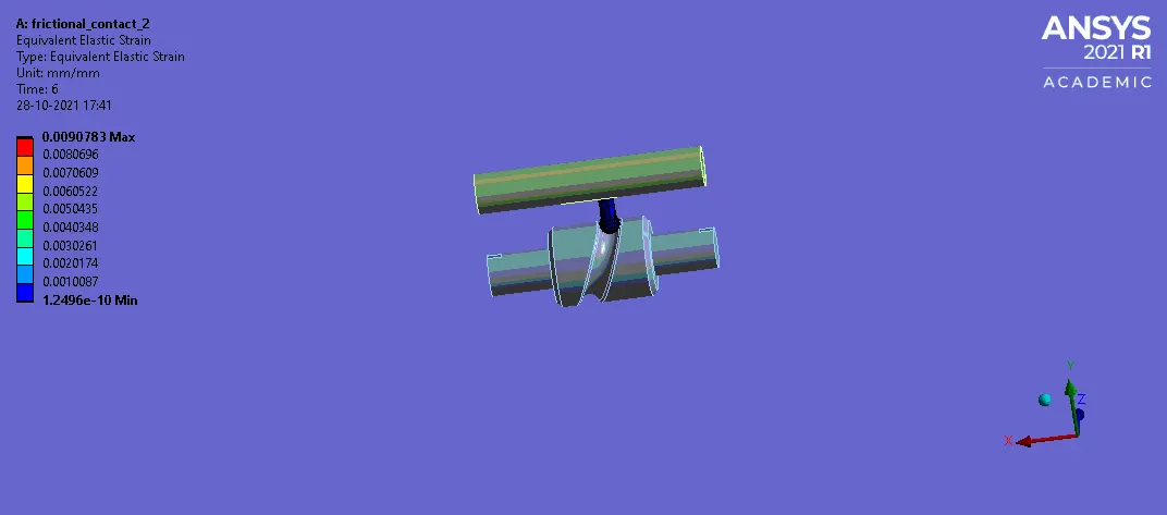
FORCE CONVERGENCE :
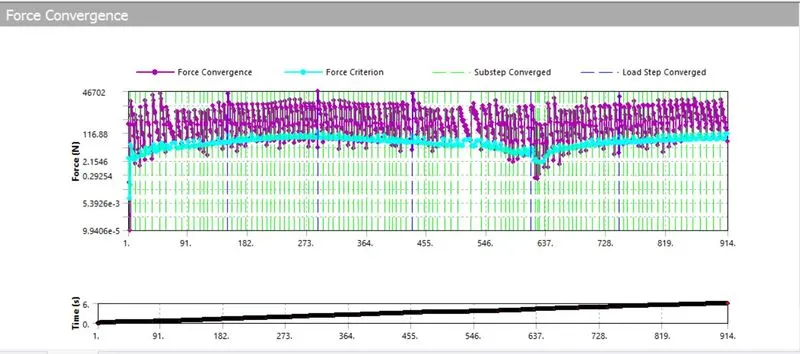
FROM THE ABOVE SIMULATION WE CAN INFER THAT THE STRESS GENERATED ON THE MODEL IS AROUND 1796.7 MPa.
Conclusion:
Thus, from the above simulation we come to conclude that , the stress generated on each case can be seen comparavitely , the frictionless contact is recommended as it generates low value of stress than the other two cases . as the co-efficient of friction increases the material imposed on the model fails .