Week 7-Long Piston With Cam
Transient analysis on a Long piston and Cam mechanism
SUMMARY:
In this project, we have performed a transient analysis on a piston-cam mechanism. Our purpose behind the transient simulation is due to unsteady condition appearing on the model. Here, the cam & follower model is taken under consideration and desired results are obtained after required boundary conditions are provided respectively.
INTRODUCTION:
A Transient analysis means analysing a system in an unsteady state. Here, We have Cam & Follower setup, the cam is inside a hollow tube provided with a translational joint, moving to and fro from a fixed point. Meanwhile, the follower traces a fixed path as the Barrel spins along an axis. The entire simulation is run for certain steps followed by, connections, joints and displacement. Mentioned analysis has been undergone a frictionless contact as well as with friction of coefficient 0.1 & 0.2 respectively.
SOLUTION:
Step 1: Part design:
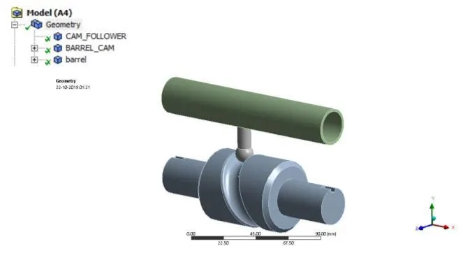
The assembly of the long piston and cam was given. Since the focus of the study is to understand the behaviour of the follower, the other two components are defined as rigid in nature. The material for all the bodies in the model was defined as structural steel.
Step 2: Connections
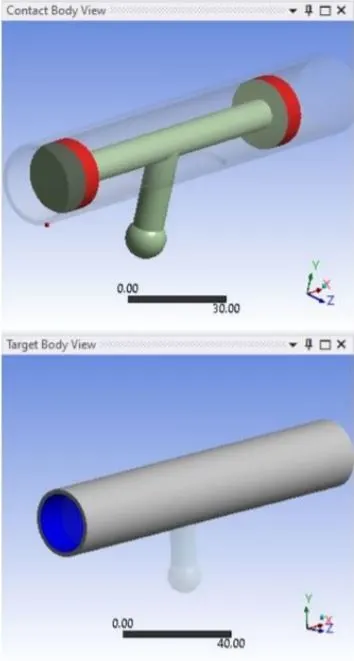
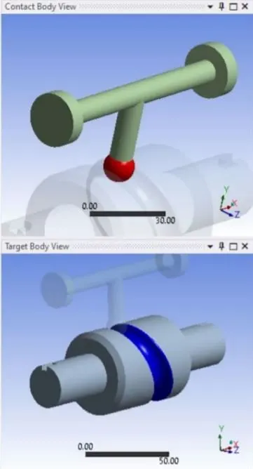
Two contacts were defined for the model, one between the follower and barrel and the second one between the follower and cam. The friction behaviour between the contacts was changed for the three cases, with no friction condition for the case-1, 0.1 for case-2 and 0.2 for the case-3.
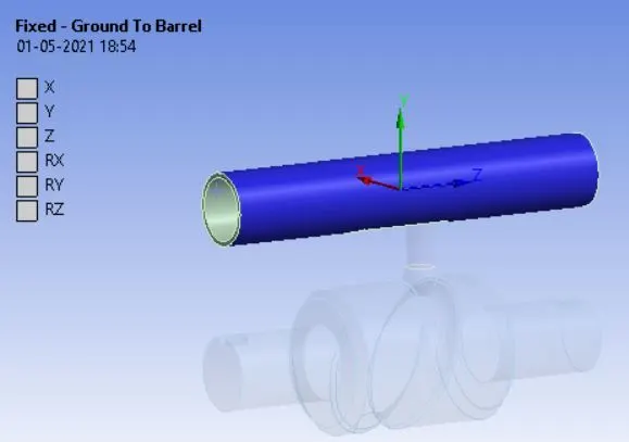
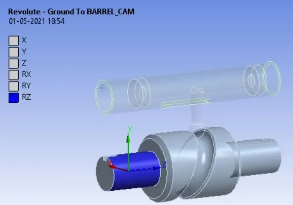
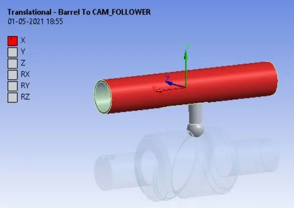
Further, three joints were defined for the model. The barrel was given a fixed condition, the cam was defined as a revolute joint and a translation joint was established between the barrel and follower.
Step 3: Meshing:
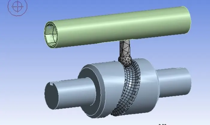
In the meshing step, a face sizing mesh was defined on the follower tip and the guideway on the cam with an element size of 3mm.
Step 4: Analysis settings:
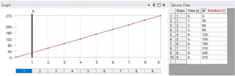
The analysis is carried out over 9 steps. For the 1 step, the initial time step is 0.1s, the minimum time step is 0.05s and the maximum time step is 0.2s. The weak springs were set as program-controlled, the large deflection was turned on and all the output controls were changed to yes condition. For step 2-9, the maximum time step was set as 0.3s with all other conditions as same. A rotation setting was given for the cam, ranging from 0 to 270 degree with a 30-degree increment.
Step 5: Results:
CASE-1: Results for frictionless conditions:
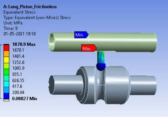
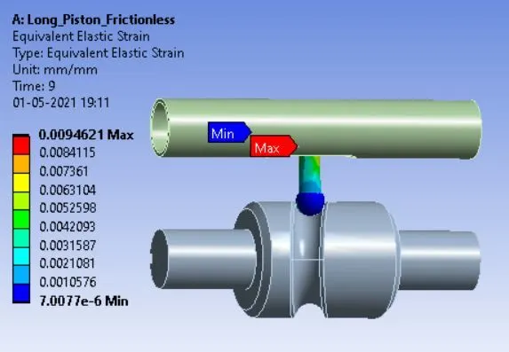
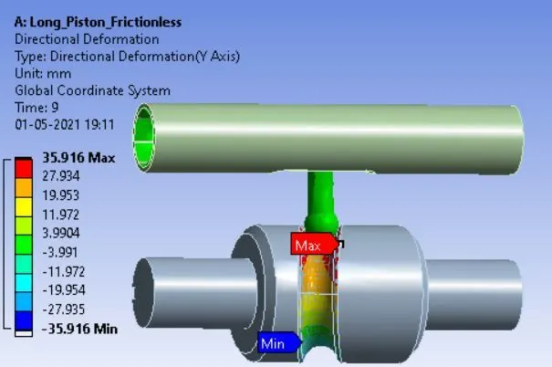
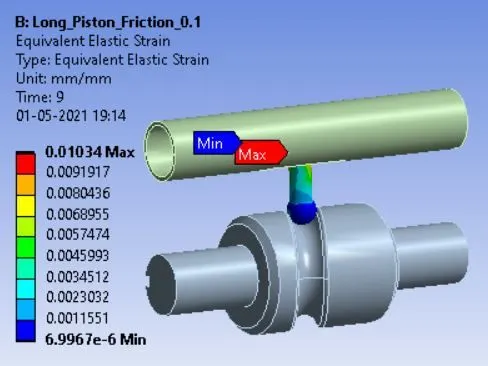
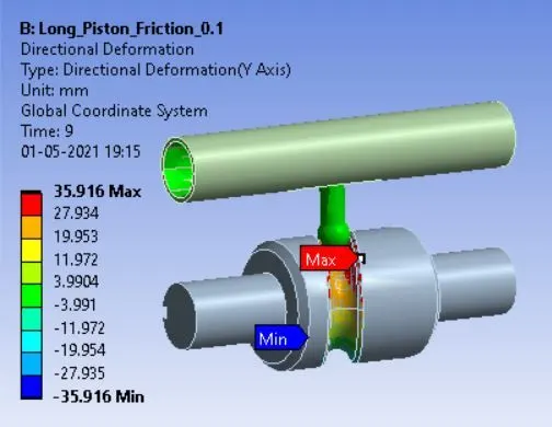
CASE-2: Results for co-efficient of friction = 0.1:

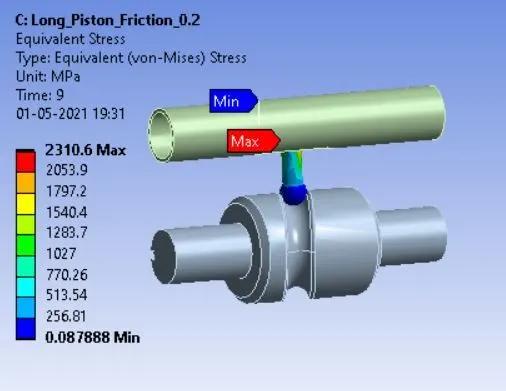
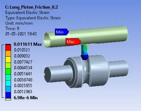
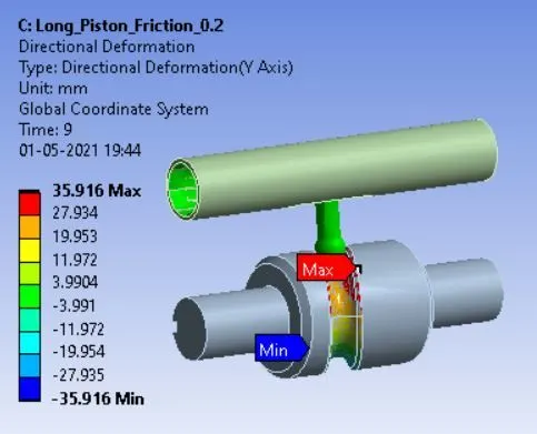
CASE-3: Results for co-efficient of friction = 0.2:
CONCLUSION:

Thus, we can see that as the coefficient of friction will increase so does the equivalent stress in a body in contact because resistance faced by the body in contact will increase. However, deformation values are same in all cases which implies it is independent of the coefficient of friction.