Week 7-Long Piston With Cam
Long Piston Cam Model
Aim
To perform a Transient analysis on a piston and cam mechanism model
Case 1: To run the analysis with Frictionless contact
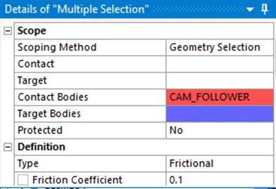
Case 2: To run the analysis with Frictional contact, with the Coefficient of Friction as 0.1
Case 3: To run the analysis with Frictional contact, with the Coefficient of Friction as 0.2
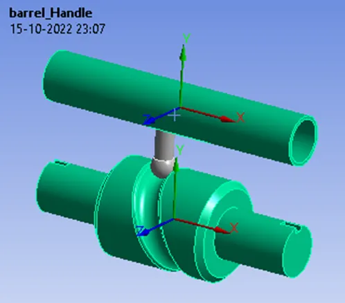
CAD Model of the object
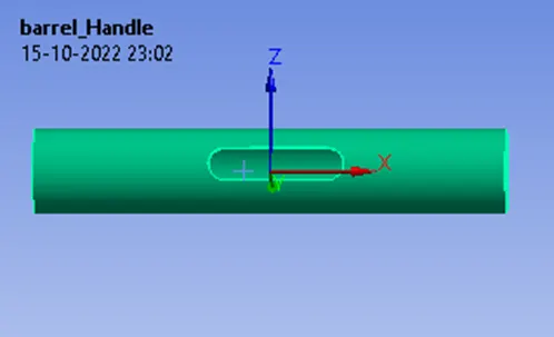
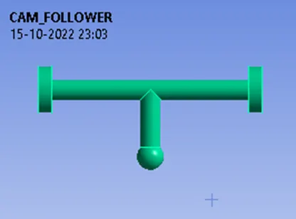
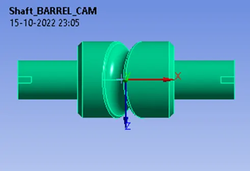
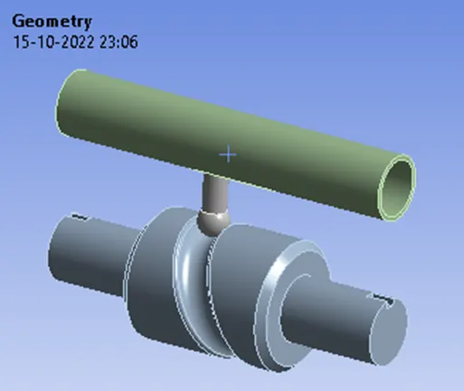
Material Used: Structural Steel
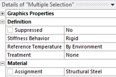
Ok in this Analysis we are interested in looking at the stress plot for the follower alone. So I am going to select the barrel_handle as well as the Shaft_BARREL_Cam and convert them to flexible to the rigid body in Stiffness Behaviour.
Why?
Because once we define these two geometries as rigid bodies the solver will consider them as a mass that is concentrated on their body centers and the solver will consider them as point masses located at the center of the mass. So now let's go ahead and define the connections and joints for this particular simulation.
Contact Details:
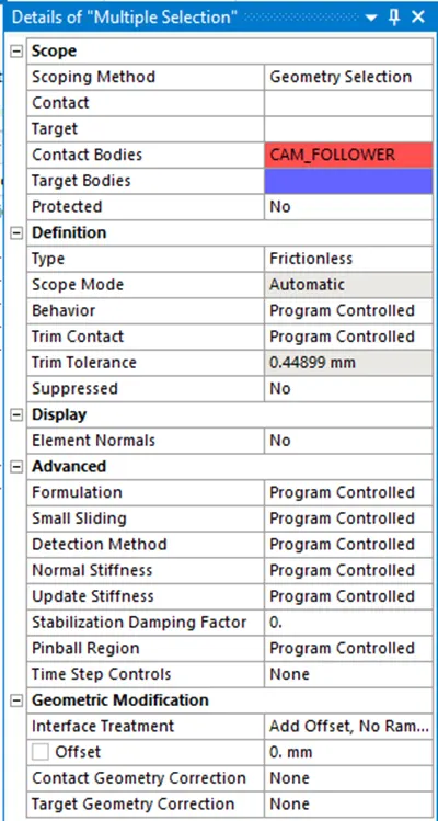
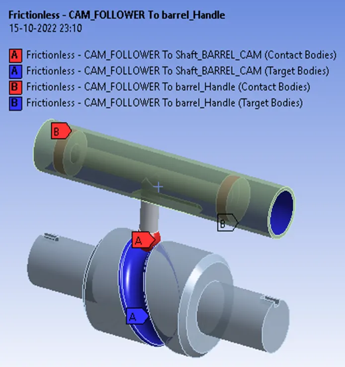
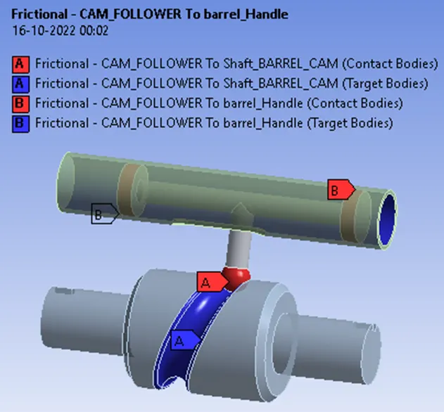
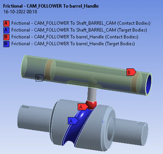
Frictionless – CAM_FOLLOWER To Shaft_BARREL_CAM, barrel_Handle
In Frictionless contact, both the normal and the contact forces are treated differently. In a normal direction, the surface can separate from each other, but they cannot penetrate into each other. So, in the tangential direction, the surfaces can slide over each other without any restriction. This solution is nonlinear because the area of contact may change as the load is applied. A zero coefficient of friction is assumed, thus allowing free sliding. The model should be well-constrained when using this contact setting.
Joints Settings
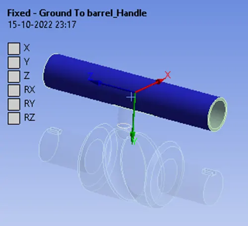
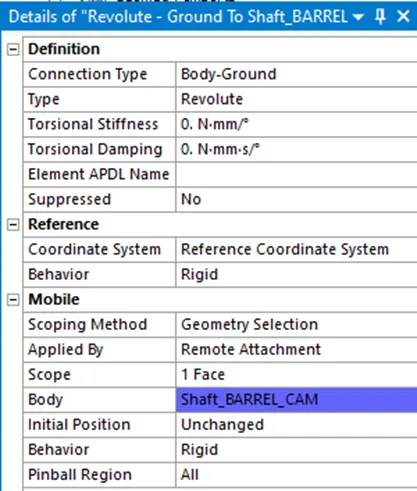
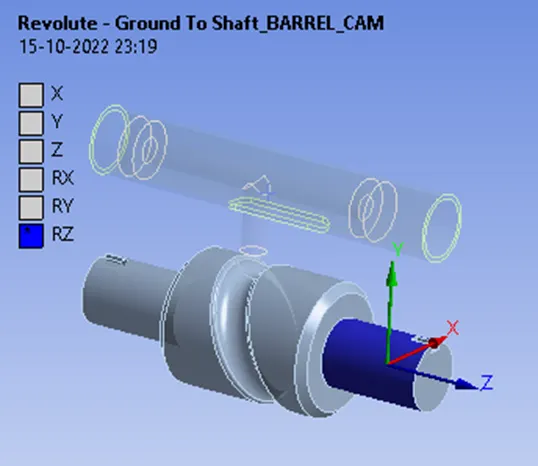
Now let us define the joints for this simulation, if you consider this mechanism as a whole you can see that the barrel_handle needs to be fixed and the Shaft_barrel_cam needs to rotate in such a way that the follower is going to follow the path of this grooved section.
Fixed Joint

Revolute Joint
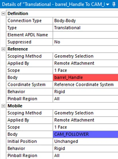
Translational Joint
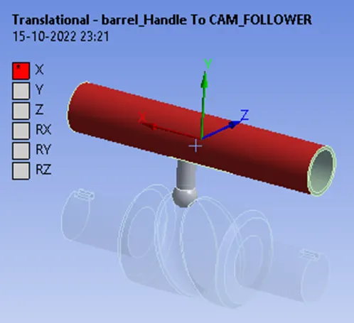
Now click on the joint (Body-Body) and insert/click Translational joint and in the Mobile – Scope – Select the cam_follower so as the cam rotates the motion of the cam is transmitted to the piston which is going to translate and this translation will be in reference with the barrel. You can see the translation is along the X- direction and the coordinates system is also perfectly aligned with the direction of the translation.
Meshing
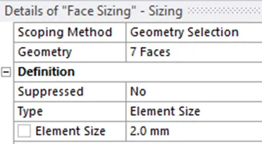
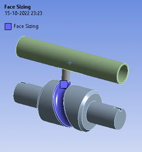
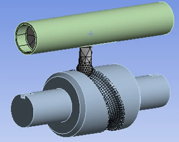
Let's insert a Face sizing for the surfaces that come in contact so this way we will be able to refine the mesh in the areas where the stress values need to be more accurate. Just input an element size of 2 mm and generate the mesh. Fine our geometry has meshed but if you notice you can see the mesh was not generated for the rigid body except for the faces we selected on the Shaft_Barrel_Cam it is because as I mentioned before that it will be considered as Point masses and the stress or strain plots will not be visible for the rigid bodies, while on the other end for the flexible bodies we will be obtaining the stress, strain as well as other simulation results. So before we proceed further click on the mesh again and switch off the adaptive sizing and generate the mesh again.
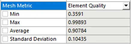
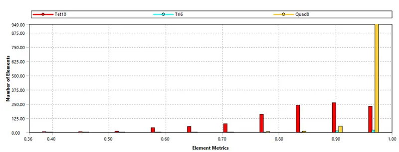
Mesh Metric: Element Quality
A mesh metric was used to identify elements based on their quality, and it can be observed that the elements of the lowest quality are minimum. The majority of the elements have very high-quality values ranging from 0.3591 to 0.99893 with an average value of 0.90784. As a result, the mesh is of reasonably good quality.
Boundary Condition: Analysis Settings
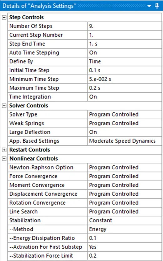
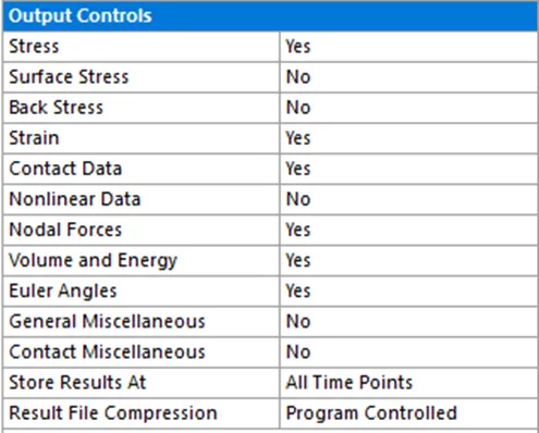
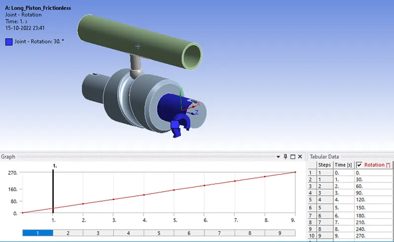
There are four steps in the simulation. Therefore, the number of steps is set to 9, solver type and weak springs are set as Program controlled, large deflection is turned on, stabilization is set to constant method to energy, the energy dissipation ratio is set to 0.1, and the output control is set to yes for all output. Similar parameters are followed for Case 2 and Case 3.
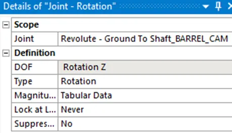
Joint Loads for Rotation
Simulation Results
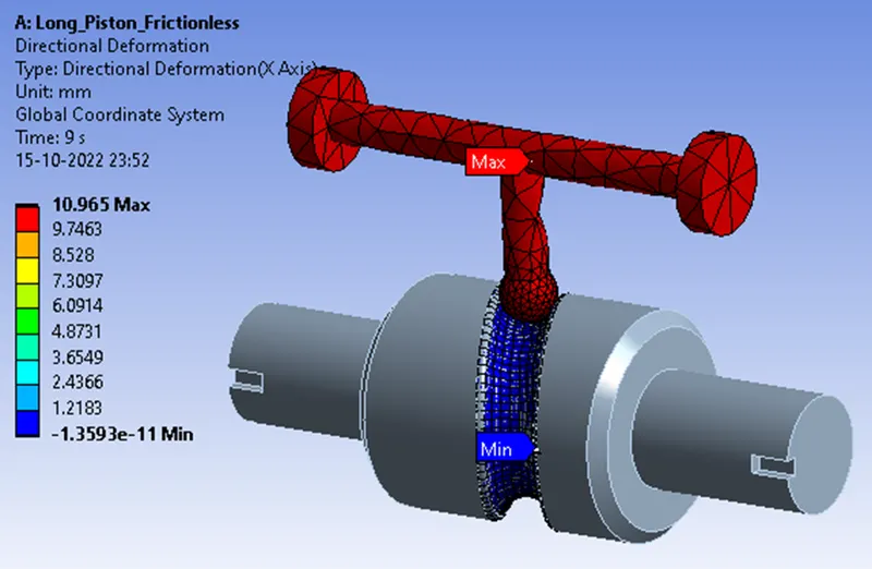
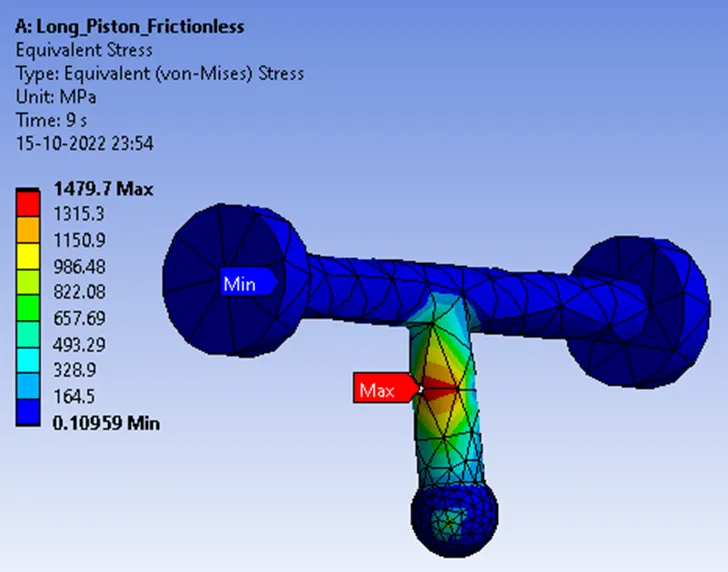
Case 1: To run the analysis with Frictionless contact
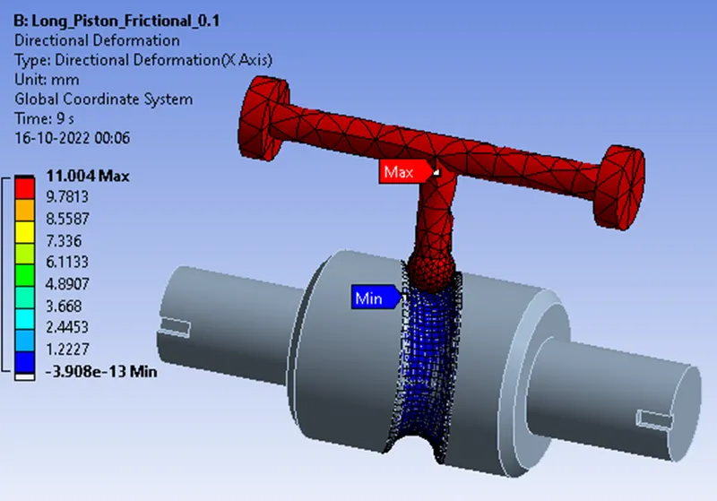
Directional Deformation
Equivalent Stress
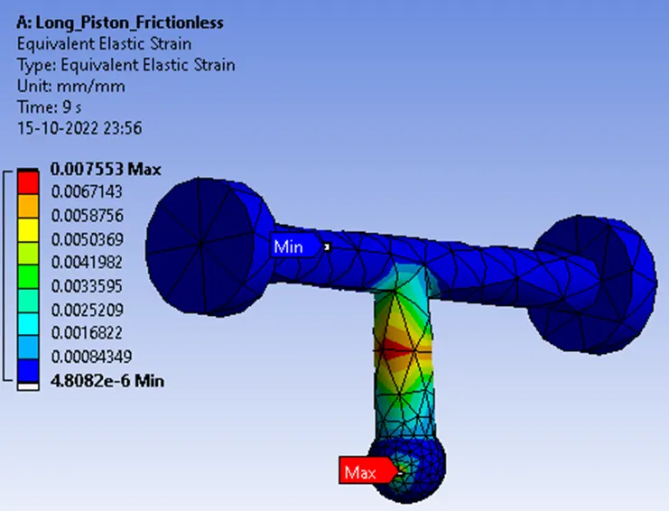
Equivalent Elastic Strain
Case 2: To run the analysis with Frictional contact, with the Coefficient of Friction as 0.1
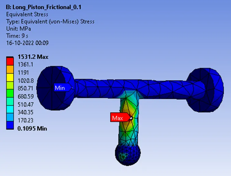
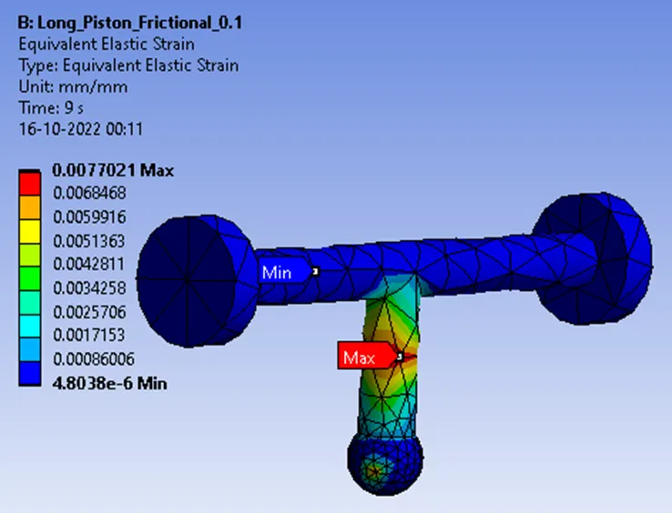
Contacts allowing separation (e.g. frictional contacts) are non-linear contacts. This state is known as “sticking.” The model defines equivalent shear stress (shear stress refers to cases where the deforming force is parallel to a surface) at which sliding on the geometry begins as a fraction of the contact pressure. Once the shear stress is exceeded, the two geometries will slide relative to each other. The coefficient of friction can be any nonnegative value, here we take it as 0.1
Directional Deformation
Equivalent Stress
Equivalent Elastic Strain
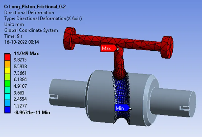
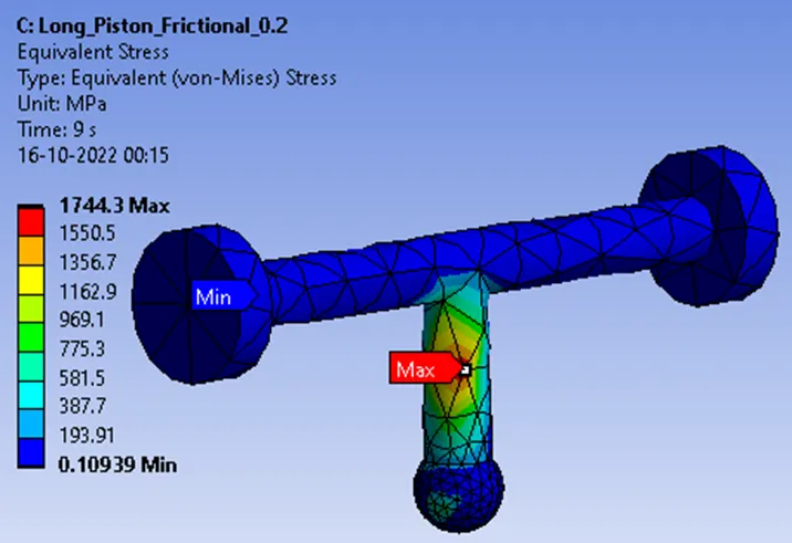
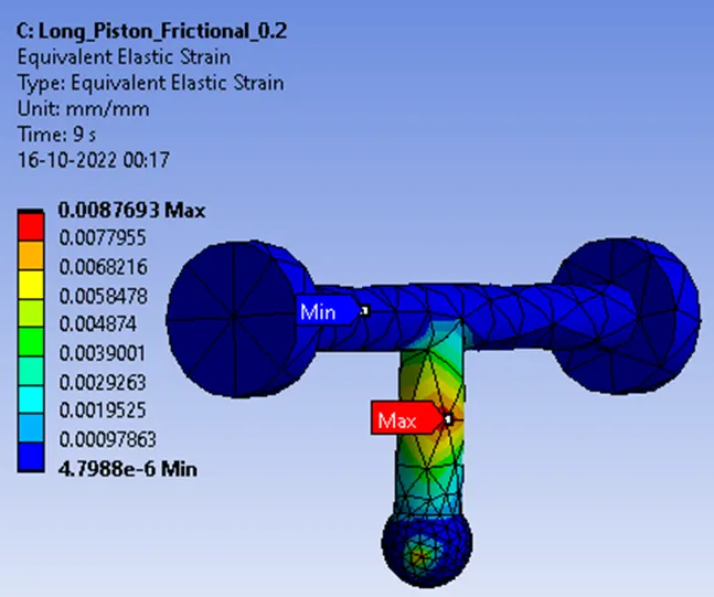
Case 3: To run the analysis with Frictional contact, with the Coefficient of Friction as 0.2
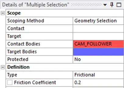
Contacts allowing separation (e.g. frictional contacts) are non-linear contacts. This state is known as “sticking.” The model defines equivalent shear stress (shear stress refers to cases where the deforming force is parallel to a surface) at which sliding on the geometry begins as a fraction of the contact pressure. Once the shear stress is exceeded, the two geometries will slide relative to each other. The coefficient of friction can be any nonnegative value, here we take it as 0.2
Directional Deformation
Equivalent Stress
Equivalent Elastic Strain
Concluding Result.
|
Analysis For |
Directional Deformation |
Equivalent Stress |
Equivalent Elastic Strain |
|
Case 1 Frictionless |
10.965 |
1479.7 |
0.007553 |
|
Case 2 Friction with 0.1 |
11.004 |
1531.2 |
0.0077021 |
|
Case 3 Friction with 0.2 |
11.049 |
1744.3 |
0.0087693 |
From the above table, we can see that as the frictional co-efficient increases the equivalent stress, strain, and Directional deformation increases. As there is friction the energy required also increases hence the stress and strain also increases. Total deformation remains constant for all three cases. More force is required to overcome the friction and force is directly proportional to stress thus the stress increases. Stress is directly proportional to strain and thus strain increases.