Week 7-Long Piston With Cam
Aim: To perform a transient analysis on a piston and cam mechanism model.
Objective: Runnig the analysis with Frictionless contact, Frictional with 0.1 and 0.2 as the frictional contact for a total of 3 cases. Find out the Equivalent Stress, Directional Deformation and Equivalent Elastic Strain and compare them for all the three cases.
Procedure:
1) To verify welds in the setup, we use the static structural tool in the analysis system toolbox to define the geometry and other input parameters for the same.
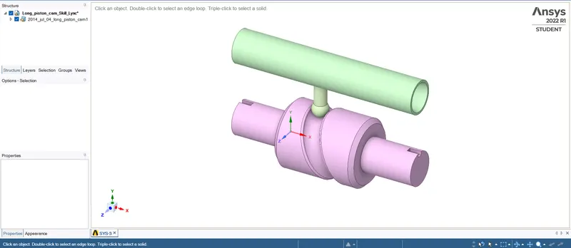
First, we open SpaceClaim to identify and rectify the errors in the geometry. In the below geometry we can see the copper rolling
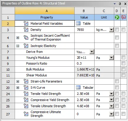
2) In the engineering data we input the material and its properties. In this case, we are using three different types of materials and their properties are shown below.
3) In the geometry of the model, all the parts are made up of Structural Steel metal.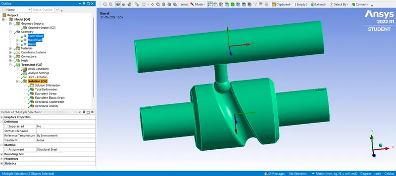
4) In connection, we have to define the contact faces of the geometry by selecting and deselecting contact or target bodies. In contacts under the connection tab, we define the type of contact as frictionless and frictional contact.
Case 1: Frictionless Contact
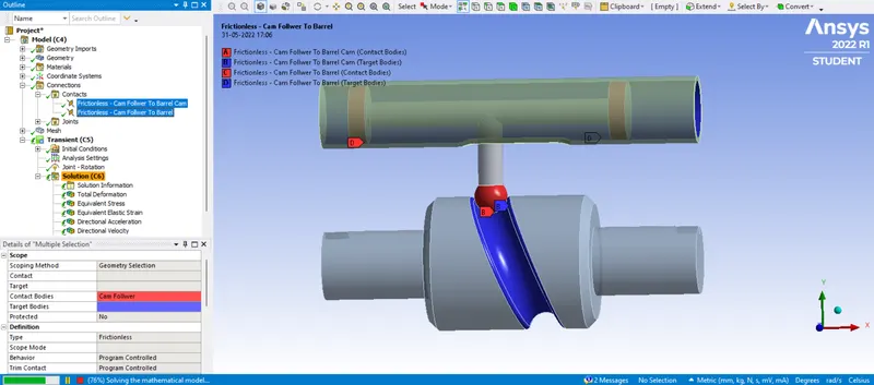
Case 2: Frictional Conctact with frictional coefficient as 0.1
Case 3: Frictional Conctact with frictional coefficient as 0.2
5) Defining Joints of the geometry for fixed, revolute and transitional movement of the body in the desired direction
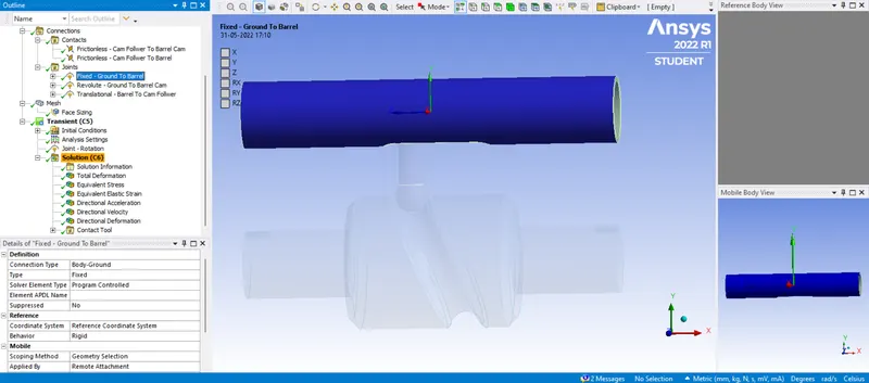
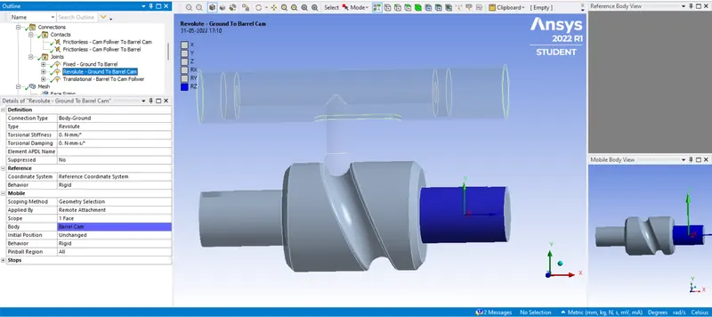
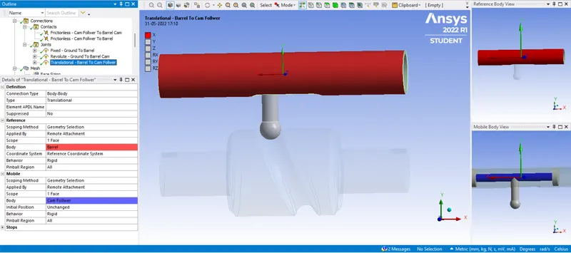
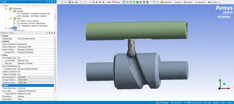
6) By opening the modelling tab, we mesh the geometry with element size as default and finer mesh size where contacts are present. Generating the mesh thereafter by right-clicking on the Mesh icon. Finer mesh is used for the workpiece which is going to get deformed wherever the workpiece comes in contact.
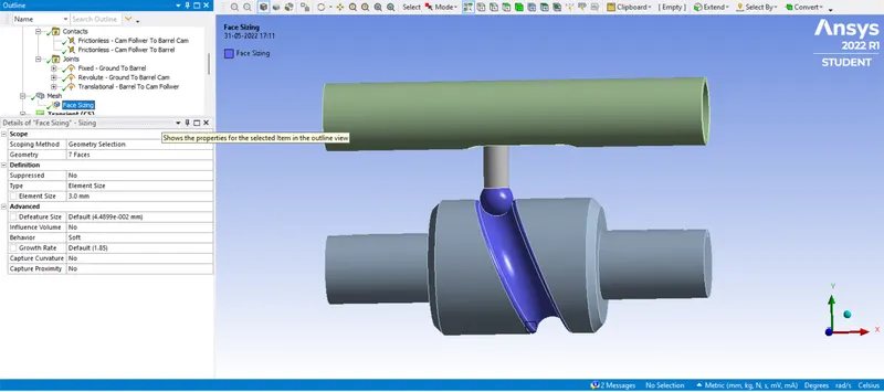
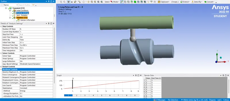
7) We open the analysis setting where stimulation is run for 14 steps for Displacement and Joint-Rotation
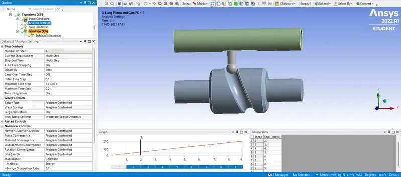
Joint-Rotation is given as shown below
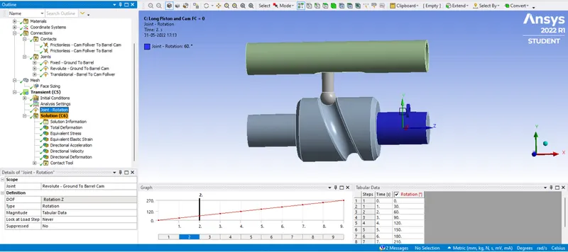
8) Setting up the solution:
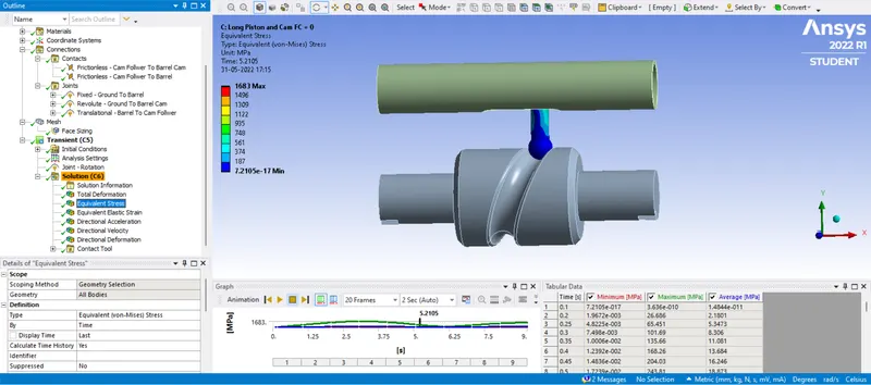
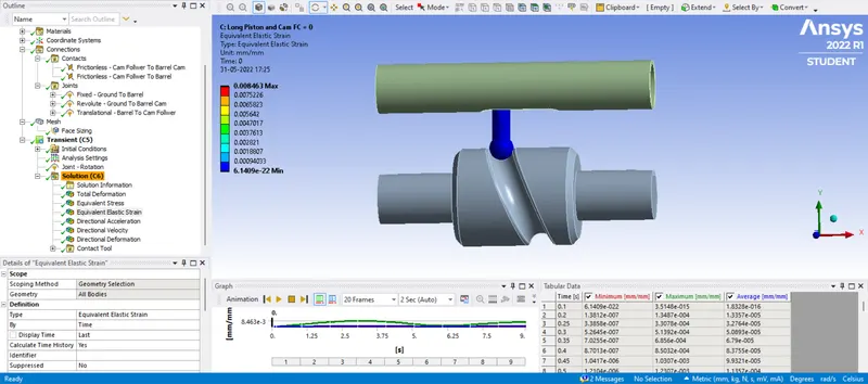
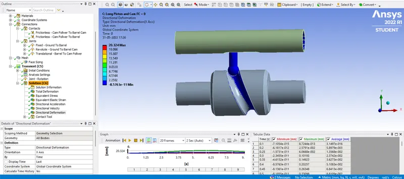
Case 1: Frictionless Contact
a) Equivalent Stress for Whole Setup:
b) Equivalent Elastic Strain for Whole Setup:
c) Directional Deformation in the X-axis:
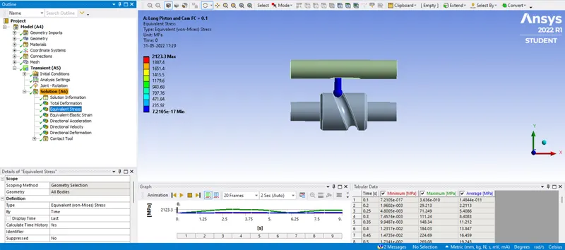
Case 2: Frictional Contact with Frictional Coefficient as 0.1
a) Equivalent Stress for Whole Setup:
b) Equivalent Elastic Strain for Whole Setup:
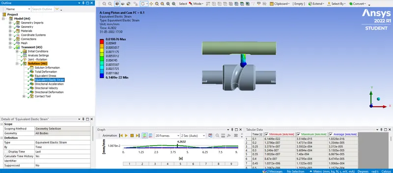
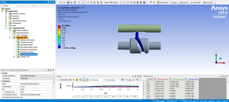
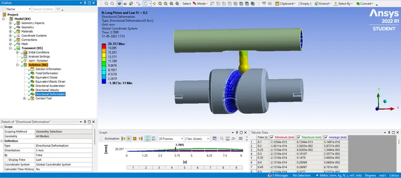
c) Directional Deformation in the X-axis:
Case 3: Frictional Contact with Frictional Coefficient as 0.2
a) Equivalent Stress for Whole Setup:
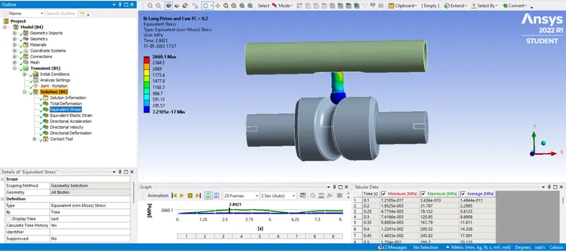
b) Equivalent Elastic Strain for Whole Setup:
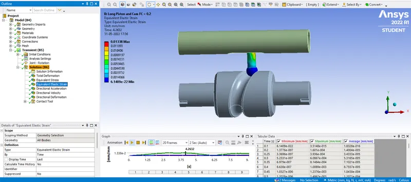
c) Directional Deformation in the X-axis:
Result:
| Material | Case 1 | Case 2 | Case 3 |
| Equivalent Stress in Mpa (Maximum) | 1683 | 2123.3 | 2660.1 |
| Equivalent Stress in Mpa (Minimum) | 7.2105e-17 | 7.2105e-17 | 7.105e-17 |
| Equivalent Elastic Strain (Maximum) | 0.008463 | 0.010676 | 0.01338 |
| Equivalent Elastic Strain (Minimum) | 6.1409e-22 | 6.1409e-22 | 6.1409e-22 |
| Directional Deformation in X-axis in mm (Maximum) | 20.324 | 20.324 | 20.357 |
| Directional Deformation in X-axis in mm (Minimum) | -8.5763e-11 | -7.7079e-10 | -1.3873e-11 |
Conclusion:
- From the above result, we can conclude that the equivalent stress is maximum in Case 3 and it is more vulnerable to fracture.
- Elastic strain is minimum in Case 1 compared to the other two Cases.
- Directional deformation is the same in all the Cases.