Week-7 Head Impact
AIM: To simulate the pedestrian head impact on Rigid wall and car hood.
Introduction:
In recent years, lightweight vehicles have become more essential in terms of fuel economy and vehicle cost. One of the most essential criteria in determining the impact of damage or mortality in the head impact test on the hood. The goal of this research is to see how the aluminium hood influenced the head impact test and whether pedestrians were injured.
Case I - Simplified model (Shell Sphere and Rigid wall)
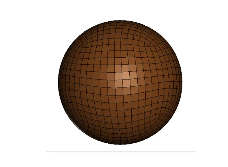
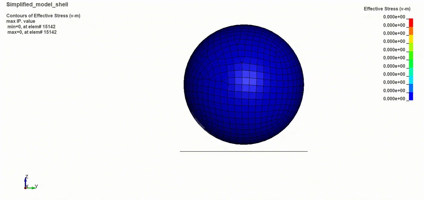
Fig: Simplified Sphere and Rigid wall Model
1.1 Material Model: MAT_001 - Elastic Material model was defined for the impacting sphere.
1.2 Section: Fully Integrated Shell element was defined with 1.5mm thickness was defined.
1.3 Hourglass: IHQ -8 was assigned to have a stable energy balance in the system during Impact.
1.4 Head Injury Criterion (HIC):
The HIC number is derived from the small but unusually significant time-dependent acceleration (a)t sustained by a person's head during an impact. The HIC criterion assigns various probabilities of head injury to different ranges of HIC numeric values.
Considering the time-dependent acceleration of the head during the crash, the following calculation can be made:
Average Acceleration can be defined as
`a ̅=1/(t_2-t_1 ) ∫_(t_1)^(t_2)a(t)dt`
Head Injury Criterion (HIC) number can be calculate using
`HIC=max{(t_2-t_1 )* [1/(t_2-t_1 ) ∫_(t_1)^(t_2)a(t) dt]}^2.5`
1.5 Result and Discussion
Firstly a simplified model was simulated to check the possible range of HIC 36 value. Since a simplified shell model was considered and there was no energy absorption, the HIC value was comparatively high. A similar pattern was observed in the energy balance curve where the impacting body conserved the complete kinetic energy and rebounded with similar energy after impact leading to a higher HIC value.
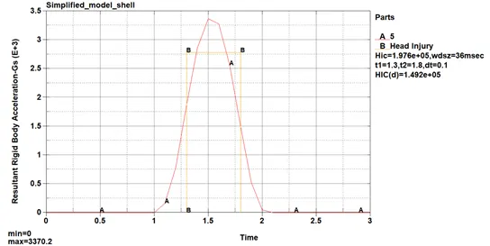
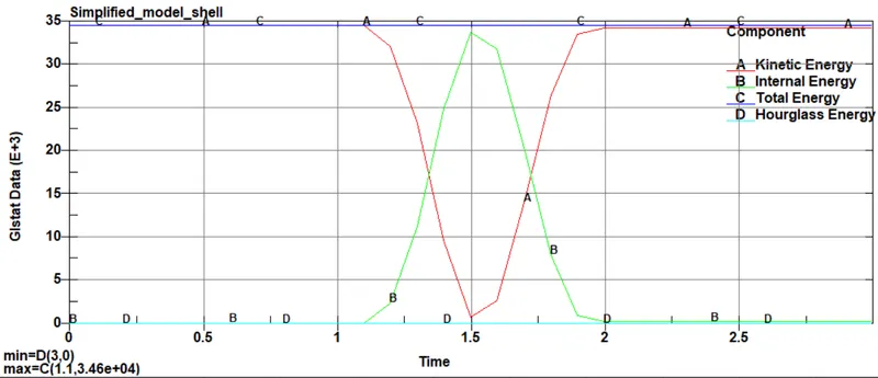
Fig: HIC and Energy balance curves for Simplified model impact on a rigid wall.
Case II - Pedestrian Headform Model impacting on a rigid wall
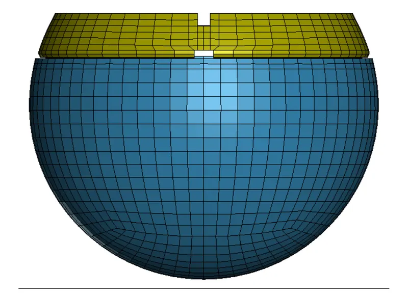
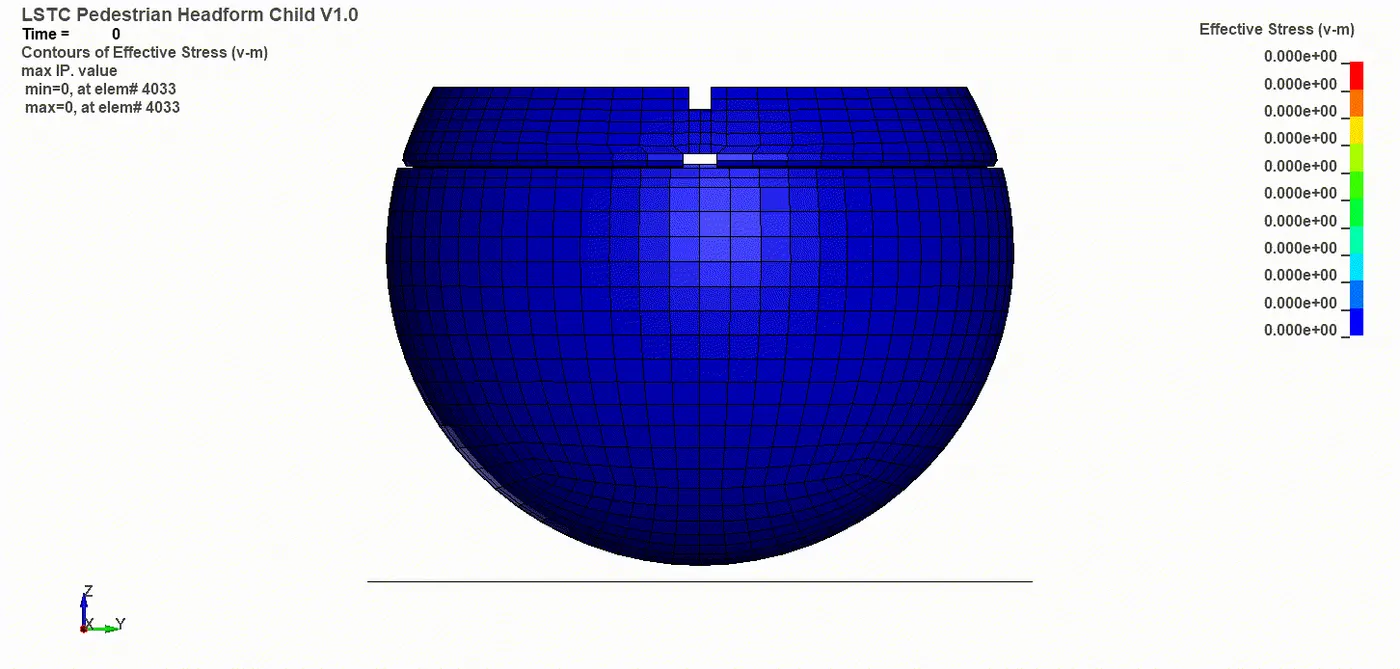
Fig: Pedestrian Headform Model and Rigid wall Model
2.1 Material Model: By default, Ogden_Rubber was utilised for the skin whereas other parts were modelled with MAT_Rigid.
2.2 Include: *Include_Include option was utilised to utilise the given Pedestrian model in the numerical simulation.
2.3 Initial Velocity: Nodal Velocity of 20kmph ~ 5.55mm/ms was defined to the imported model.
2.4 Contact Definition: Single surface contact was defined to prevent self penetration as it was observed that the skin material underwent deformation.
2.5 Result and Discussion
2.5.1 HIC 36 and Energy Curve Comparison
This HIC 36 obtained for the pedestrian model was comparatively lower to the impact of the spherical elastic body on the rigid wall. But further reduction can be expected if the impacting surface is an energy-absorbing body. Since the rubber skin absorbs some impact energy and deforms, clearly evident from the energy graph, there is a significant drop in HIC 36 value is evident.
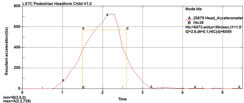
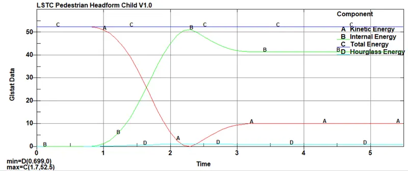
Fig: HIC and Energy balance curves for Pedestrian model impact on a rigid wall.
2.5.2 Stress vs Strain Curve Comparison
The stress and strain curves are shown in the figure below where a maximum stress of about 6.88 MPa is obtained and a max effective plastic strain is obtained about 0.003. Similar data is seen in the Stress vs Strain curve obtained in the model. The Rubber skin was selected to obtain the maximum effective stress and plastic strain respectively.
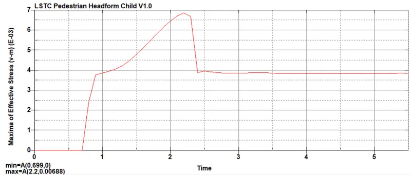
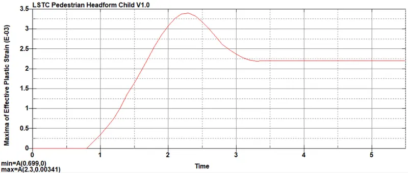
Fig: (a) Maximum Effective Stress (b) Maximum Effective Plastic Strain
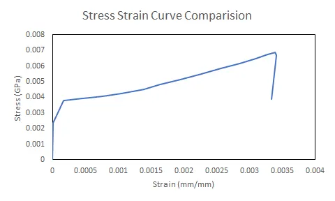
Fig: (a) Stress vs Strain Curve for Pedestrian model impact on Rigidwall (Max)
Case III - Pedestrian Headform Model impacting at`45^o`on a rigid wall
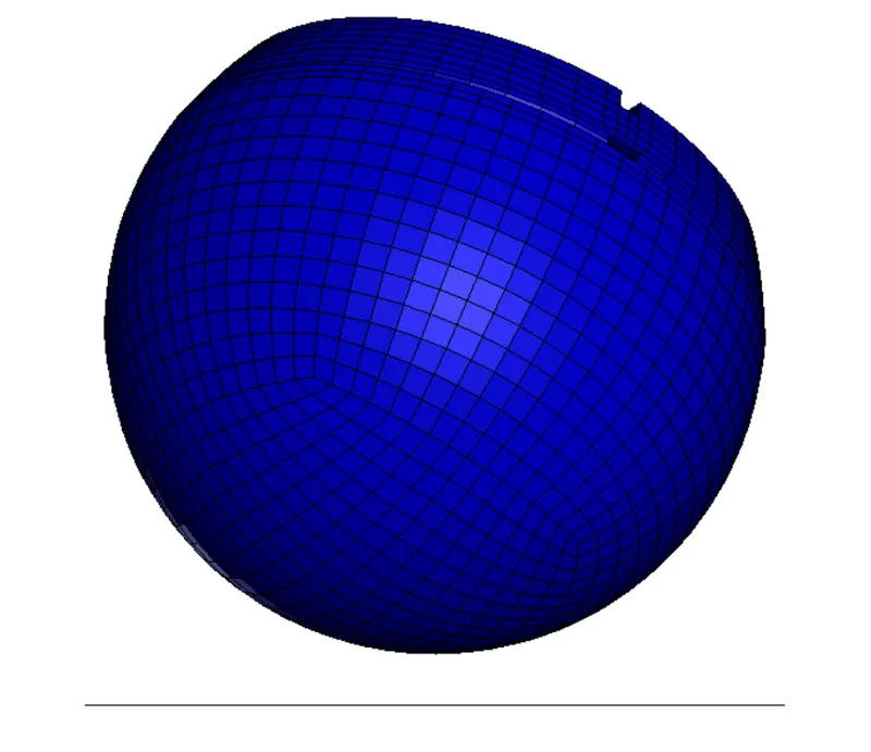
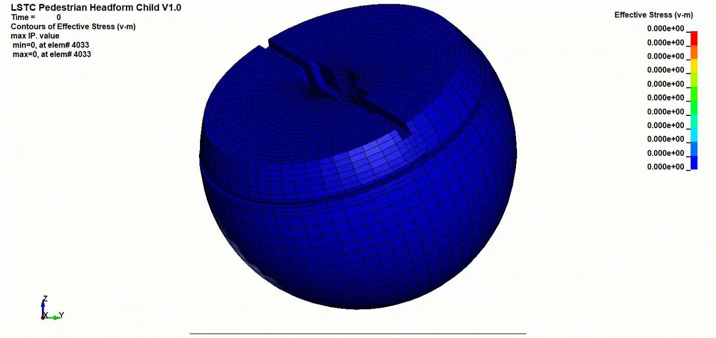
Fig: Pedestrian Headform Model impacting at `45^o` on `Rigidwall Model
3.1 Material Model: By default, Ogden_Rubber was utilised for the skin whereas other parts were modelled with MAT_Rigid.
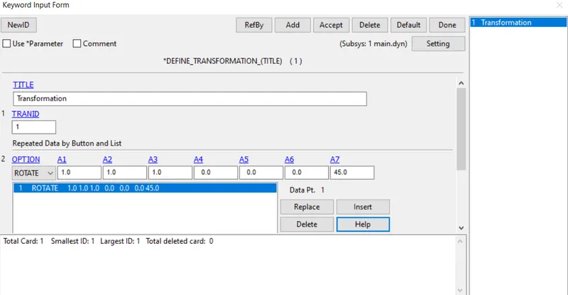
3.2 Include: *Include_Transform option was utilised to orient the given Pedestrian model at `45^o` in the numerical simulation.
3.3 Initial Velocity: Nodal Velocity of 20kmph ~ 5.55mm/ms was defined using the local coordinate defined in the pedestrian model.
3.4 Contact Definition: Single surface contact was defined to prevent self penetration as it was observed that the skin material underwent deformation.
3.5 Define_Transformation: was utilised to define the degree of orientation for the given pedestrian model.
3.6 Result and Discussion
3.6.1 HIC 36 and Energy Curve Comparison
This HIC 36 obtained for the pedestrian model impacting at an angle was comparatively lower when compared to the normal impact of the pedestrian model on the rigid wall. The angled impact resulted in 4376 HIC which was approximately 50% lower than the normal impact HIC. The reason for degreased HIC was clearly evident from the energy comparison curve, where it was observed that the kinetic energy and the internal energy curves were relatively closer.
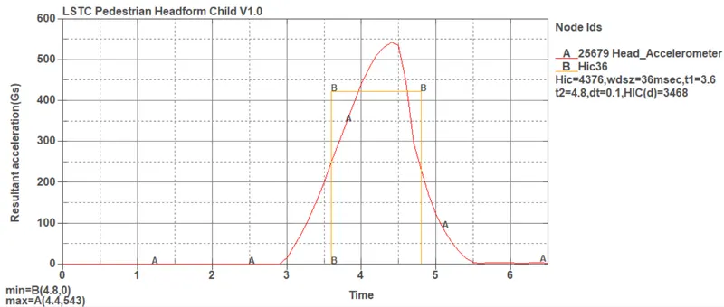
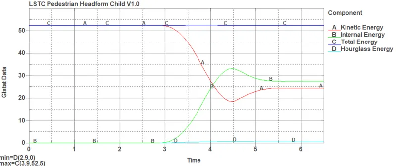
Fig: HIC and Energy balance curves for Pedestrian model impact on a rigid wall.
3.6.2 Stress vs Strain Curve Comparison
The stress and strain curves are shown in the figure below where maximum stress of about 5.92 MPa is obtained and a max effective plastic strain is obtained about 0.002. On comparison with normal impact data, the angeled impact stress was 13.95% less.
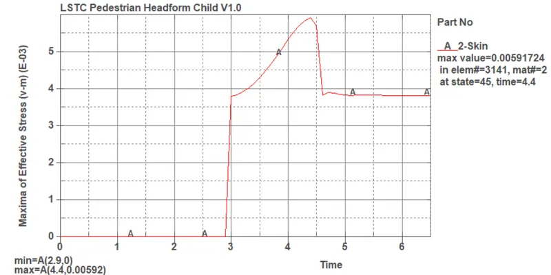
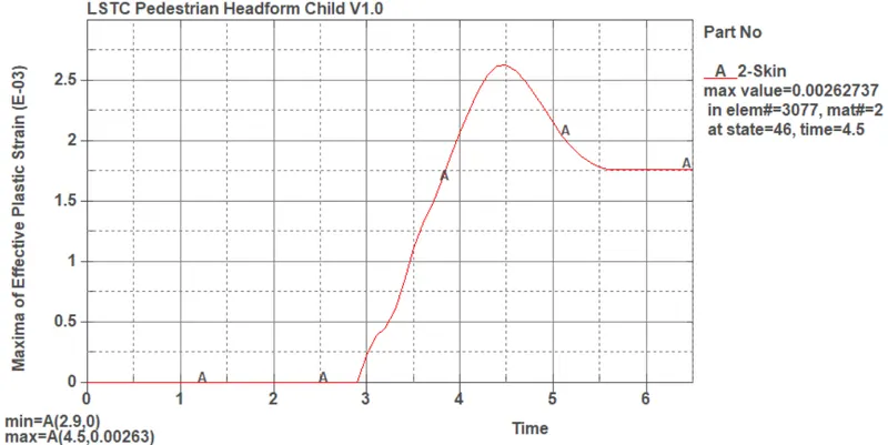
Fig: (a) Maximum Effective Stress (b) Maximum Effective Plastic Strain
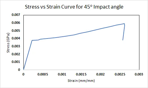
Fig: Stress vs Strain Curve for Pedestrian model impacting at `45^o`
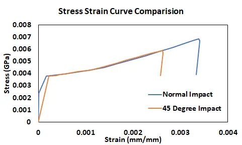
Fig: Stress vs Strain Comparision for normal and oblique impact
Case IV - Pedestrian Headform Model impacting on a car hood
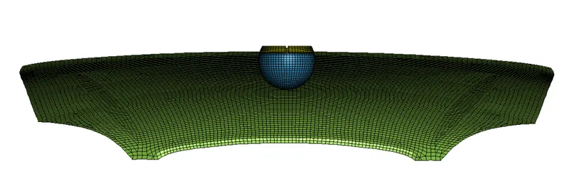
Fig: Pedestrian Headform Model impacting on a car hood
4.1 Include: *Include_Include option was utilised to import the hood and the pedestrian model into the simulation.
4.2 Material Model: MAT_24, was utilised to define the material properties for the hood. Aluminium material properties were assigned to the structure.
4.3 Initial Velocity: Nodal Velocity of 20kmph ~ 5.55mm/ms was defined to the imported model.
4.4 Contact Definition: Surface to Surface contact was defined to simulate the contact between the hood and the pedestrian head model and Single surface contact was defined to prevent self penetration as it was observed that the skin material underwent deformation.
4.5 Boundary Condition: The translation motion of the hood was constrained in the X, Y and Z directions.
4.6 Result and Discussion
4.6.1 HIC 36 and Energy Curve Comparison
A more realistic HIC36 value was obtained. At a peak acceleration of 30.7mm/ms^2, HIC of 80.3 was obtained. The energy balance curve clearly depicted the energy absorption by the car hood and a relative reduction in the kinetic energy of the pedestrian head model. Negligible losses due to hourglass energy was observed.
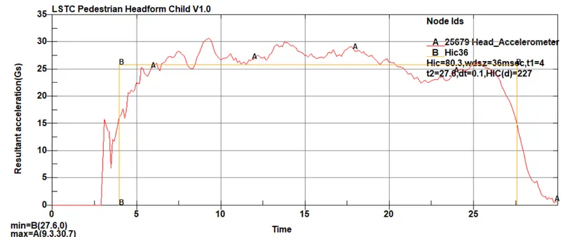
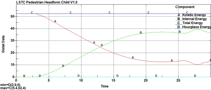
Fig: HIC and Energy balance curves for Pedestrian model impact on a car hood.
4.6.2 Stress vs Strain Curve Comparison
The stress and strain curves are shown in the figure below where maximum stress of about 3.84 MPa is obtained and a max effective plastic strain is obtained about 0.003. Similar data is seen in the Stress vs Strain curve obtained in the model. The Rubber skin was selected to obtain the maximum effective stress and plastic strain respectively.
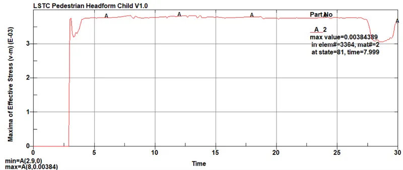
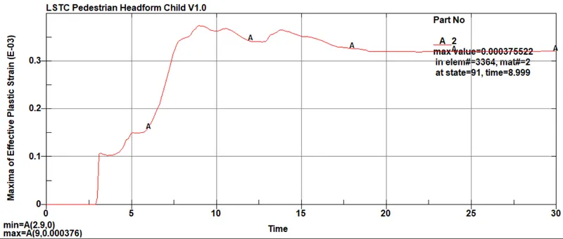
Fig: (a) Maximum Effective Stress (b) Maximum Effective Plastic Strain
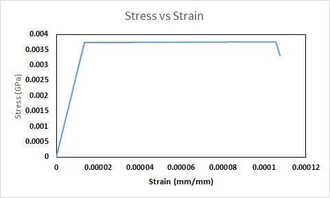
Fig: (a) Stress vs Strain Curve for Pedestrian model impact on Rigidwall (Max)
Case V - Pedestrian Headform Model impacting at`45^o`on a Car Hood
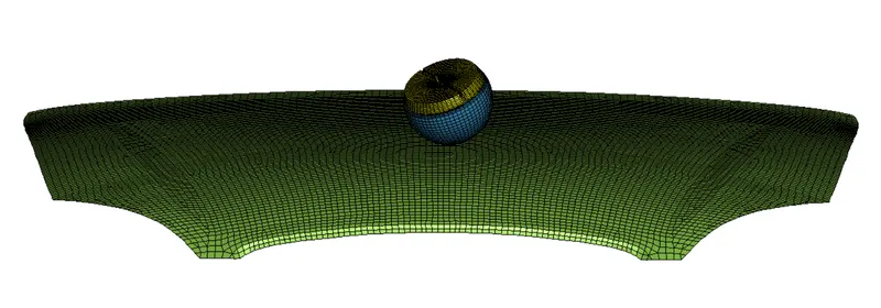
Fig: Pedestrian Headform Model impacting at `45^o` on `Car Hood
5.1 Material Model: By default, Ogden_Rubber was utilised for the skin whereas other parts were modelled with MAT_Rigid and MAT_24, was utilised to define the material properties for the hood. Aluminium material properties were assigned to the structure.
5.2 Include: *Include_Transform option was utilised to orient the given Pedestrian model at `45^o` in the numerical simulation.
*Include_Include option was utilised to import the hood and the pedestrian model into the simulation.
5.3 Initial Velocity: Nodal Velocity of 20kmph ~ 5.55mm/ms was defined using the local coordinate defined in the pedestrian model.
5.4 Contact Definition: Single surface contact was defined to prevent self penetration as it was observed that the skin material underwent deformation.
5.5 Define_Transformation: was utilised to define the degree of orientation for the given pedestrian model.
5.6 Result and Discussion
5.6.1 HIC 36 and Energy Curve Comparison
This HIC 36 obtained for the pedestrian model impacting at an angle was comparatively lower when compared to the normal impact of the pedestrian model on the metallic car hood. The angled impact resulted in 65.86 HIC which was approximately 17.98% lower than the normal impact HIC. The reason for decreased HIC was clearly evident from the energy comparison curve, where it was observed that the kinetic energy and the internal energy curves were relatively closer.
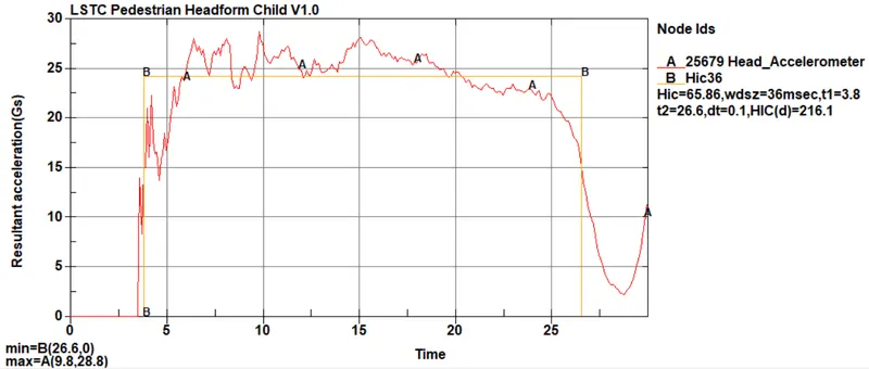
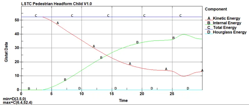
Fig: HIC and Energy balance curves for Pedestrian model impact on a rigid wall.
3.6.2 Stress vs Strain Curve Comparison
The stress and strain curves are shown in the figure below where maximum stress of about 5.92 MPa is obtained and a max effective plastic strain is obtained about 0.002. In comparison with normal impact data, the angeled impact stress was 13.95% less.
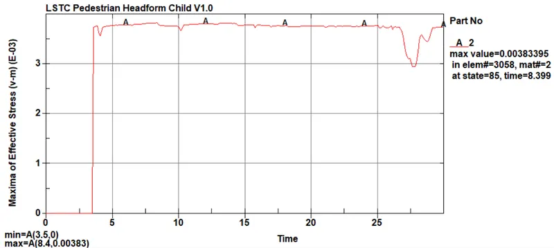
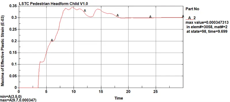
Fig: (a) Maximum Effective Stress (b) Maximum Effective Plastic Strain
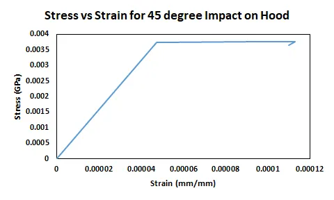
Fig: Stress vs Strain Curve for Pedestrian model impacting at `45^o`
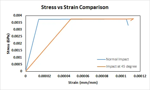
Fig: Stress vs Strain Comparision for normal and impact at 45 degree
From the fig, it was concluded that though the peak stress remains the same for both the impact conditions, impact at an angle undergoes larger deformation to reach the same stress as in normal impact.
Conclusion
- A significant difference in HIC 36 value was observed when the impact on the rigid wall was compared with the metallic deformable body. This can be attributed to the fact that the HIC value is concerned with the deceleration of the body during the impact process. In case of impact against the rigid wall, most of the energy is conserved and the impacting body rebounds with comparatively the same velocity leading to higher HIC values whereas when impact takes place with the deformable body, the impacting surface absorbs energy leading to deceleration of the impacting body. This leads to HIC 36 value in an acceptable range.
- Normal and Oblique Impact: Greater HIC value was obtained in case of normal impact signifying lower contact surface and lower energy absorption, whereas when the impact was simulated at `45^o`, the contact surface is greater leading to greater energy absorption. Thus, the HIC value for angled impact was lower.