Head Impact
Head Impact
Objective
To simulate a head impact test and calculate Head Impact Criterion for the following cases:
- Simple Head Model and rigid wall
- Pedestrian Headform Model and rigid wall
- Pedestrian Headform model and meshed hood model
Deliverables:
- The impact simulation of a simple head impact with the Rigid wall.
- The impact simulation of the Headform provided the Rigid wall with the Stress / Strain plots and acceleration plot.
- The impact simulation of the head form with the Hood with the Stress / Strain plots and acceleration plot. For the hood, you can use Aluminium.
- The Stress / Strain plot from the Rigidwall simulation should be compared with the Stress / Strain plot from the Hood Simulation and there should be a detailed explanation if there is any difference in the plots.
Theory
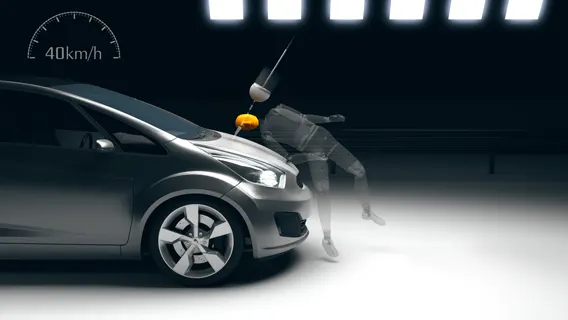
About 14 percent of all road fatalities in Europe are pedestrians, with children and the elderly being at greatest risk. Pedestrians comprise one of the main categories of vulnerable road users, which also include cyclists and motorcyclists.
Most pedestrian accidents occur within city areas where speeds are moderate. The head, the lower body and the legs are amongst the most frequently injured body regions. To estimate the potential risk of head injury in the event of a vehicle striking an adult or a child, a series of impact tests are carried out at 40 km/h using an adult or child head form impactor. Impact sites are then assessed and the protection offered is rated as good, adequate, marginal, weak or poor
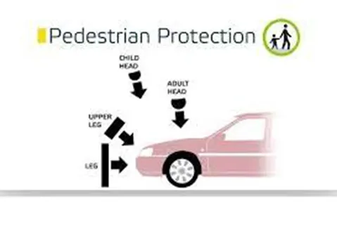
The head injury criterion (HIC) is a measure of the likelihood of head injury arising from an impact. The HIC can be used to assess safety related to vehicles, personal protective gear, and sports equipment.
Normally the variable is derived from the measurements of an accelerometer mounted at the center of mass of a crash test dummy’s head, when the dummy is exposed to crash forces.
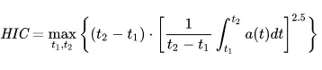
HIC(d)=0.75446(Free motion head form HIC) + 166.4, head injury criteria for Anthropomorphic test dummy
where t1 and t2 are the initial and final times (in seconds) chosen to maximize HIC, and acceleration a is measured in gs (standard gravity acceleration). The time duration, t2 – t1, is limited to a maximum value of 36 ms, usually 15 ms.
This means that the HIC includes the effects of head acceleration and the duration of the acceleration. Large accelerations may be tolerated for very short times.
Higher values of HIC indicate a higher probability of getting high-level injuries.
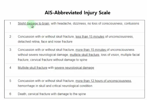
At HIC of 650
- 90% of level one injury
- 55% of level 2 injury
- 20% of level 3 injury
- 5% of level 4 injury
Procedure
- After Importing the keyword file of the simple head model, we can start by applying the boundary conditions
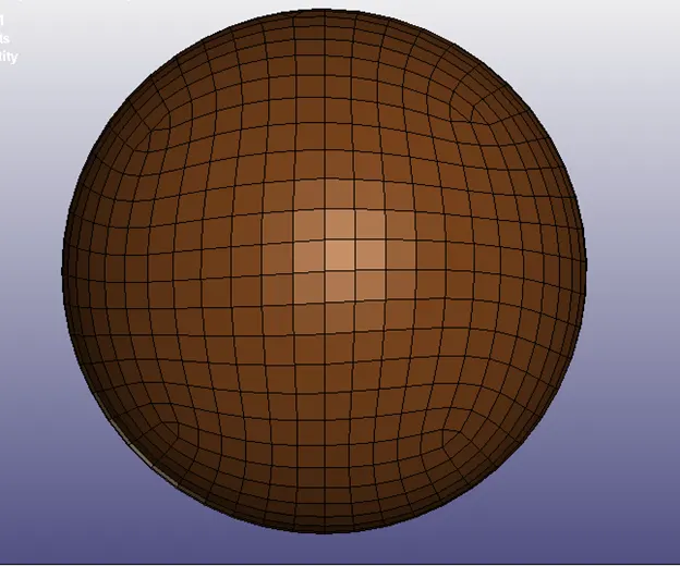
Using Create Entity option, create the rigid wall
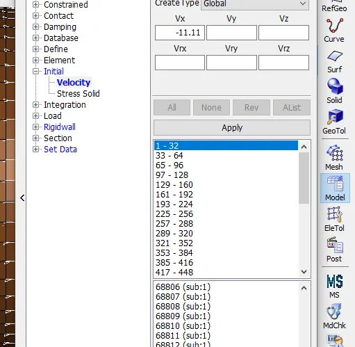
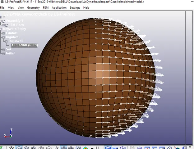
Create an initial velocity of 11.11mm/ms using create entity option
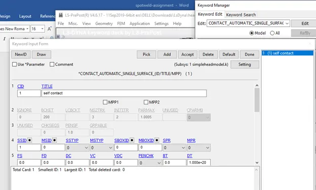
Contact
Create an automatic single surface Keyword to define self contact
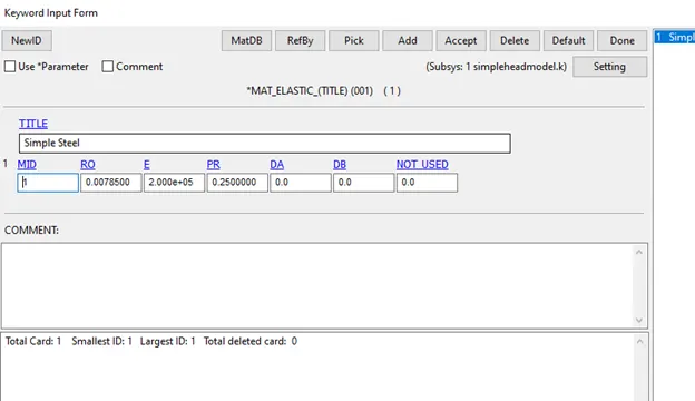
Use Simple Steel for the material.
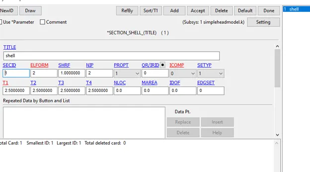
Define the section shell property.
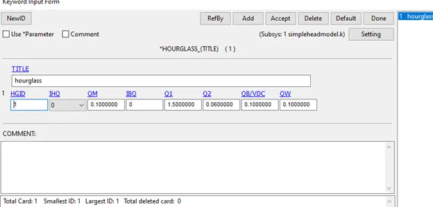
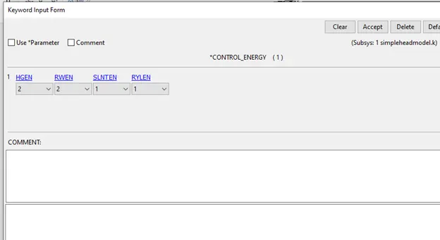
Create an hourglass card and control energy card.
Creating Section and Node
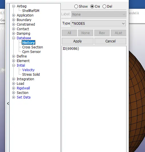
- In create Entity Option, under Database
- Create a history on a node on the head model.
Output Files
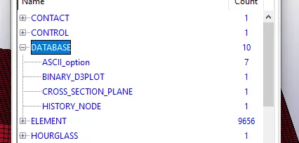
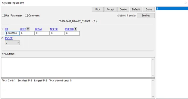
- In the database, create the d3plot and Ascii keywords
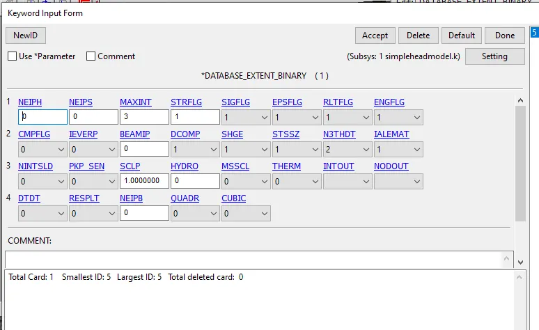
- Create extent binary and set STRFLG to 1.
- In Ascii, enable Glstat, Matsum and Nodout
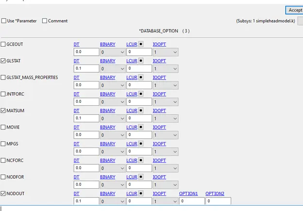
Create D3Plot
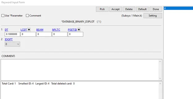
Control
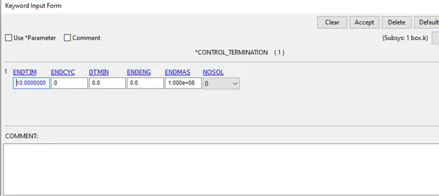
- Create a Control Termination Keyword
Check the keywords using the model checker for errors
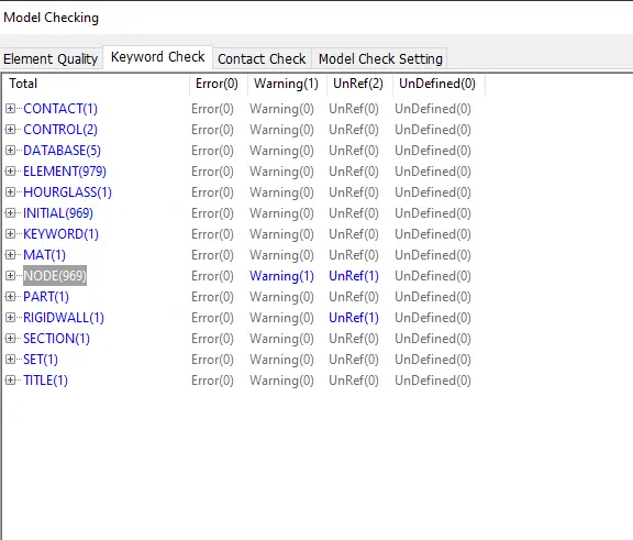
No errors only warnings and unref.
After this run the simulation using the ls Dyna solver
Headform+rigid wall
- Define a transformation
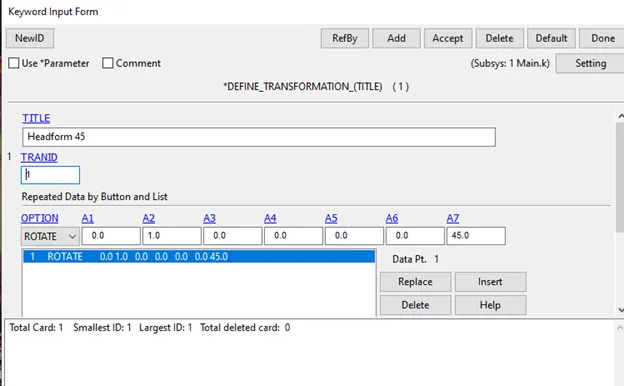
- Use include transform and refer the headform file located in the same folder, else you need to define the directory. Refer the tranid appropriately.
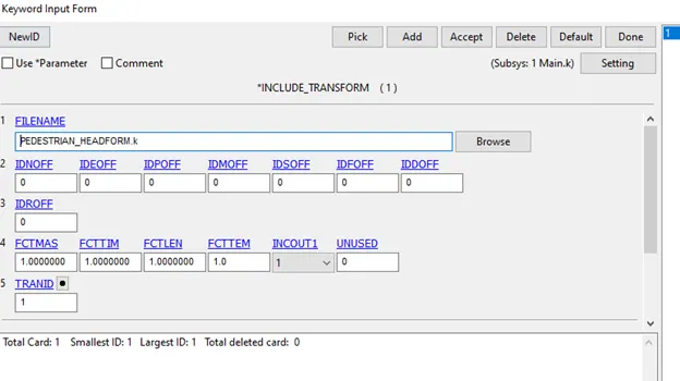
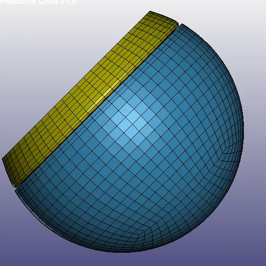
Save the file and open it.
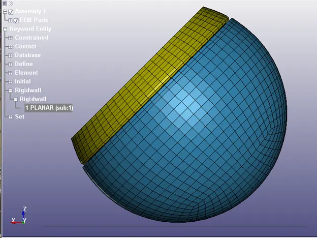
Define the rigid Wall on the bottom of the head model, the XY plane,
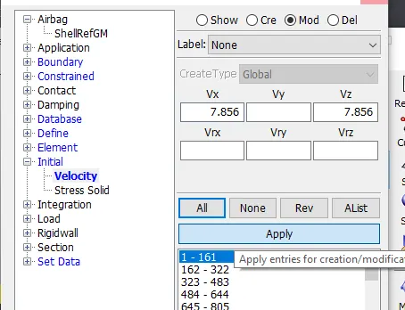
Define the velocity in the x and z-axis. Convert the diagonal vector of 11.11mm/ms to the horizontal and Vertical Components. Take angle as 45 degrees.
Enable Ascii matsum, glstat and nodout.
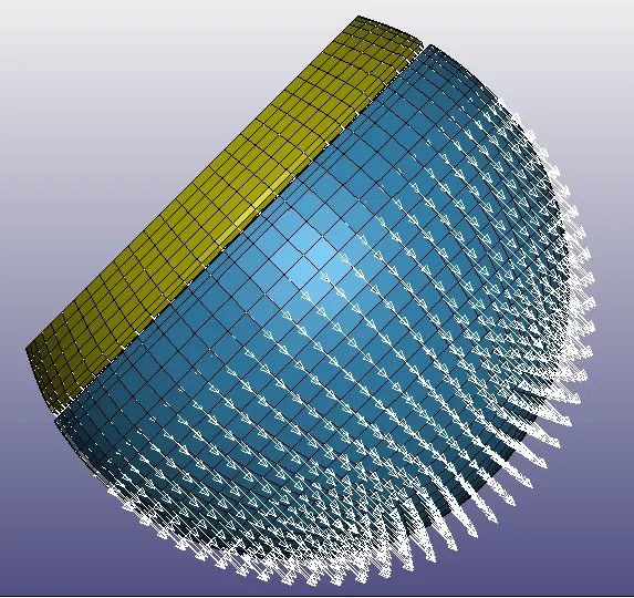
Create Database D3 Plot for 0.1.
Check for errors in the model checker.
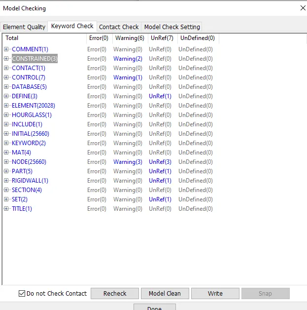
No errors only Warnings and unref.It is acceptable to run the simulation.
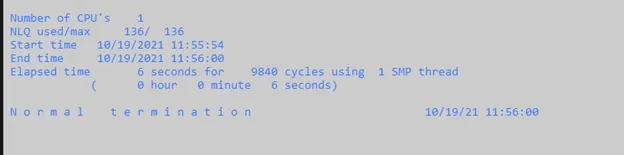
Make sure that the folder has no spaces and the termination is normal termination.
Headform model and meshed hood
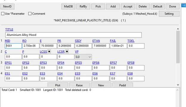
Open the meshed hood file and assign the material and section card for the hood. Make sure the units are consistent with the headform model.
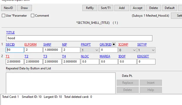
Add the headform model using define transform and include transform like in the previous case
After that use, include, include keywords and refer to the meshed hood file in the same folder.
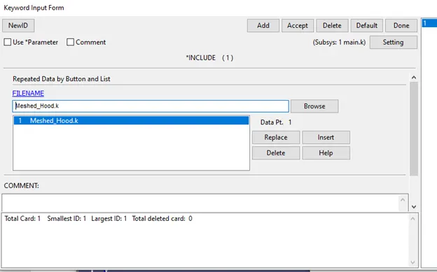
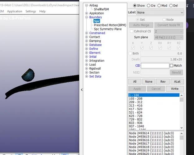
Set an SPC boundary condition, making the meshed hood rigid on all axis.
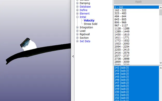
Similar to the previous case create initial velocity in x and z-axis.
In this case, we will be using a termination time of 20ms as the impact does not happen in 10ms.
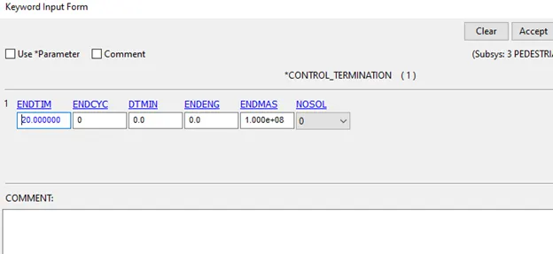
Create d3plot and Ascii options similar to the previous cases.
Run the model in the lsdyna solver.
Post Processing
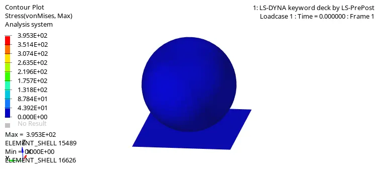
Since we are using a simple head model and elastic steel, there is no deformation taking place and after impact, it bounces back.
Hood+rigid
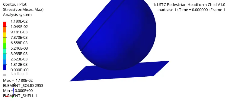
On comparing this to the simple head model, it can be seen that on impact, the head model slides over compared to bouncing back seen in case 1. This can be seen as more realistic compared to the simple head model.
Hood+Head model
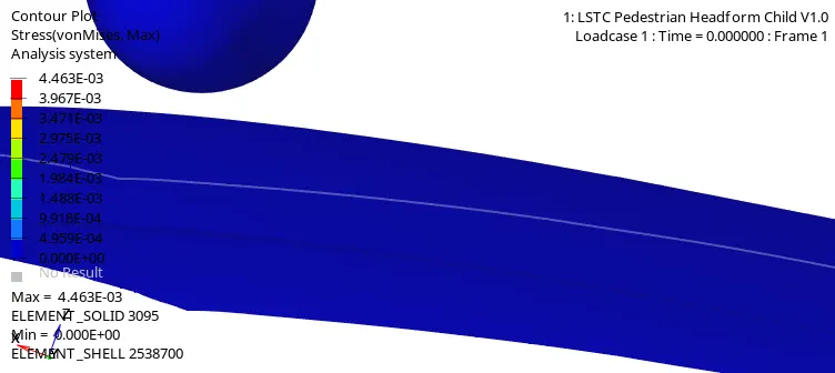
In this case, it can be noted that impact happens significantly later compared to the previous cases. This can be corrected using the transform command on the hood so that it is closer to the headform model.
Similar to the previous case, after impact, the head model slides over the hood.
This is because velocity has 2 components, x and z components, and in both cases, only the z component gets absorbed by the rigid wall/hood. So the horizontal component of velocity is not fully converted into internal energy and thus the headform model slides across the surface.
Stress and Strain Graphs
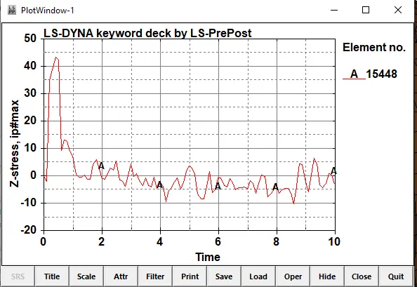
The stress peaks at around 43Gpa on impact. Due to the simple nature of the model, there is no deformation observed.
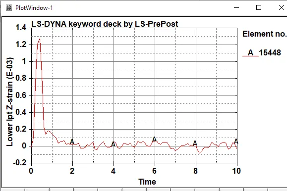
Strain peaks at around 1.3* 10-3 at the point of impact. This is an extremely small value that is not visible during the animation. This is because simple elastic steel was chosen as the material.
HIC And Acceleration
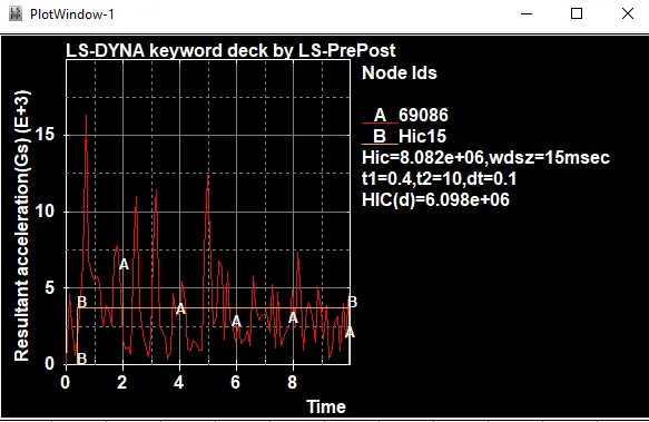
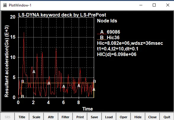
It can be seen that HIC16 and HIC36 values are the same.HIC values of above 1000 are considered bad as the probability of severe life-threatening injuries is extremely high. However, it should be noted that these values may be high due to the simple nature of the case.
Headform And Rigid
Stress and Strain
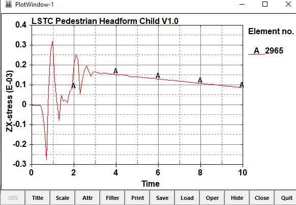
The stress peaks around 0.3x 10⁻³ Gpa and has a minimum value of -0.25 x 10⁻³ Gpa. These values occur at the point of impact and indicate compressive force on impact. This can be seen as during the animation after impact the elements compress.
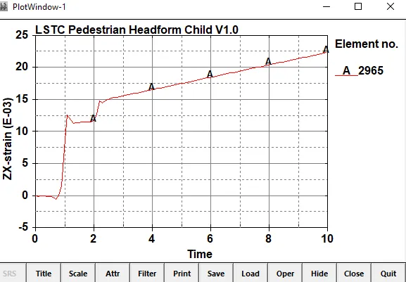
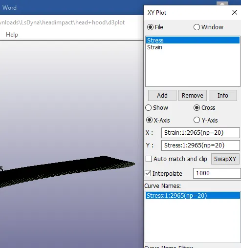
On cross plotting
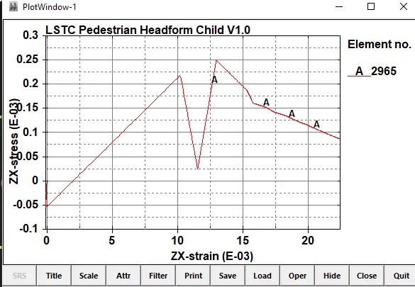
It can be seen that the stress linearly increases till failure, the large drop in stress, after that it once again increases. This can be because of new elements coming in contact with the rigid wall.
HIC
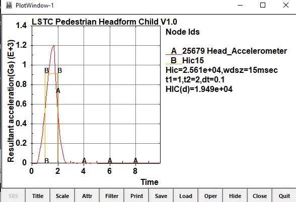
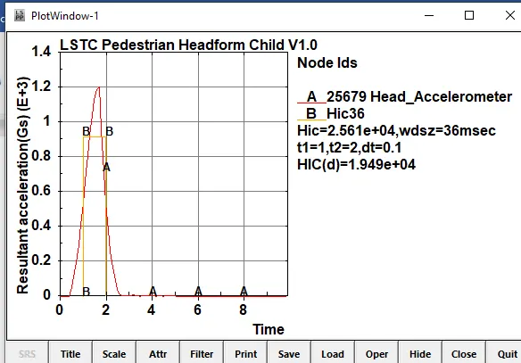
It can be seen that HIC16 and HIC36 values are the same. They are significantly less compared to the simple head model case. HIC values of above 1000 are considered bad as the probability of severe life-threatening injuries is extremely high. However, it should be noted that these values may be high due to the simple nature of the case.
Hood+Headform
Stress and Strain
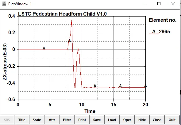
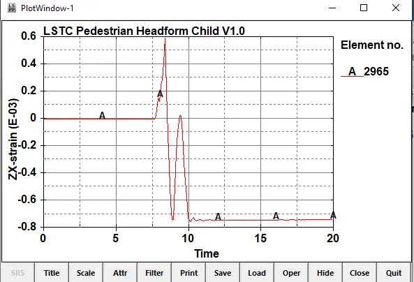
On cross plotting,
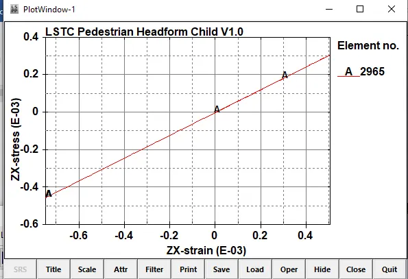
It can be seen that the stress-strain graph is linear. This indicates that there is a transfer of forces from the head to the hood along with no deformation of elements due to the low values of stress and strain.
Comparing this to case 2 it can be inferred that there is transfer of energy to the hood which does not happen with the rigid
wall.The stress is also lower and the strain is significantly less in case 3 compared to case 2 further suggesting transfer of energy.
HIC
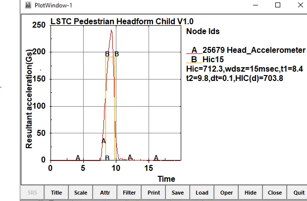
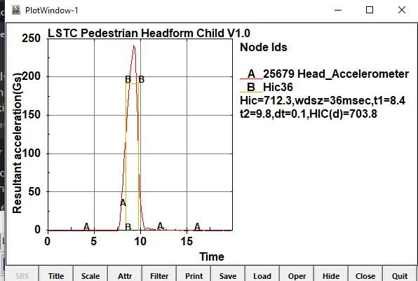
It can be seen that HIC16 and HIC36 values are the same.HIC values of above 1000 are considered bad as the probability of severe life-threatening injuries is extremely high. However, it should be noted that in this case, the value of HIC and HIC(d) is 712.3 and 703.8.
A Hic-15 value of 700 indicates that the risk of severe injury is around 5%.
Learning Outcomes
- Setting up and interpreting head impact tests in ls Dyna
- Using include and transform keywords to refer to different files
- Interpreting HIC values from ls Dyna
Conclusion
When the vehicle is engineered, manufacturers must ensure that any vehicle variant selected by the testing body can meet the required safety criteria. Consequently, as it is impossible to compute all the occupant injury responses for all vehicle structure manufacturing tolerance variants, a more statistical approach is usually used to encompass all eventualities. Some OEMs use a 6-Sigma approach for their vehicle design targets and ensure that all internal certification tests lie within 3σ (standard deviations) of the legal target. These OEM internal targets are kept confidential and vary from one OEM to another.
In this project, we modelled head impact tests using the Simple and pedestrian child headform model, observed the differences between the two. The pedestrian headform was set up using a meshed hood model and a rigid wall. It can be observed that there are significant differences in the HIC values, both 15 ms and 36ms and that a HIC value of below 1000 was only found when the headform was tested with the meshed hood.
The significant difference between case 2 and case 3 is because of the difference in the rigid wall and the hood. The rigid wall will reflect the energy on impact with minimal absorption of energy while the hood will absorb energy on impact leading to a lower and more accurate HIC value.