Week-7 Head Impact
AIM : Head Impact Simulation with three diffrenet cases as given below
Case 1: simple head model impacted on rigid wall
Case 2: child head foam impacted on rigid wall
case 3 : child head foam impacted on aluminium hood model.
Procedure
Case 1 :
open LS PREPOST and open the given .k file
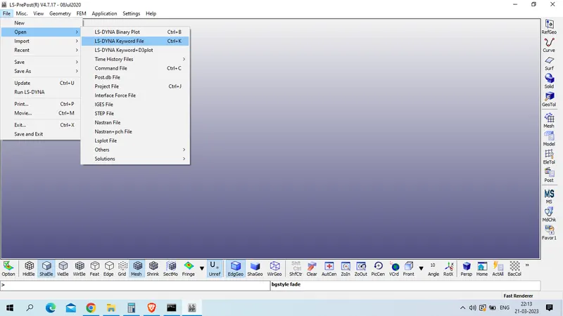
file >> open >> LS_DYNA keyword file
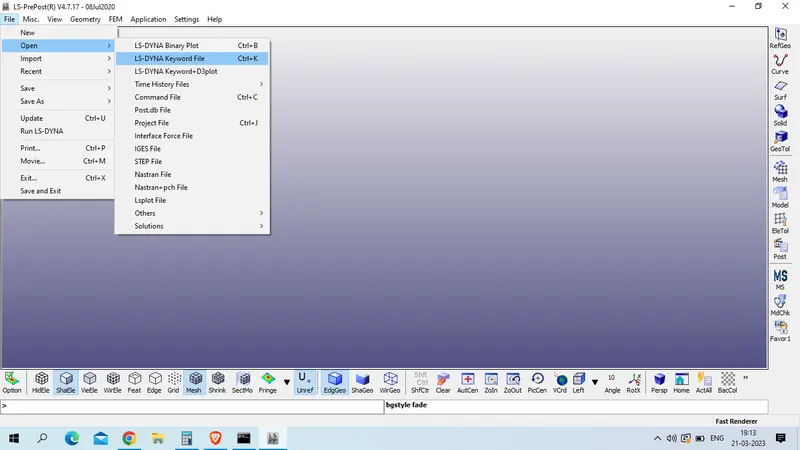
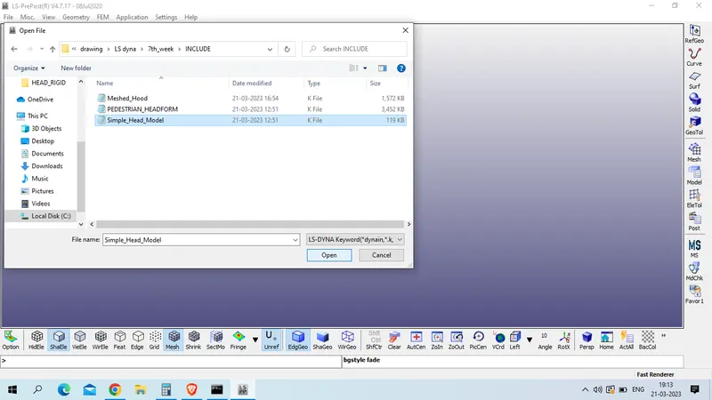
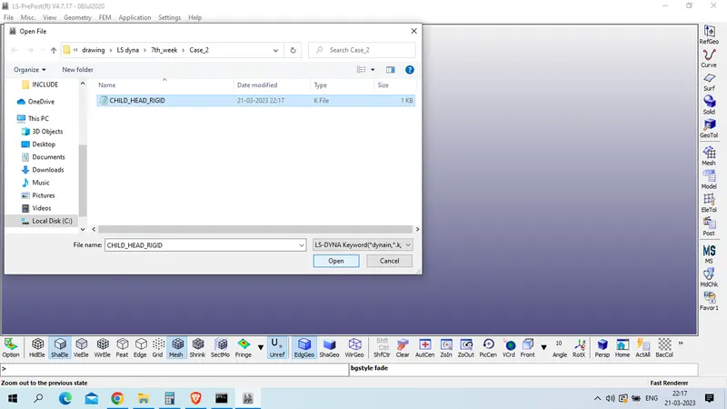
Select file >> open
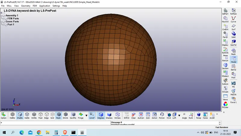
Check the keyword manager file >> as we have shell model only
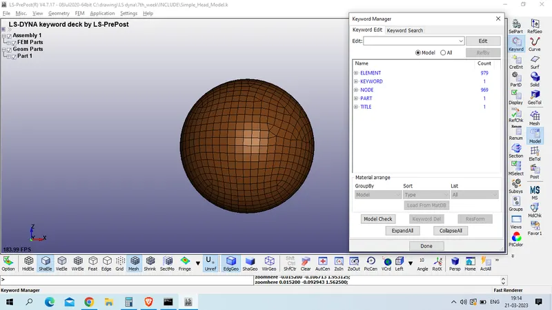
now we will create section for shell
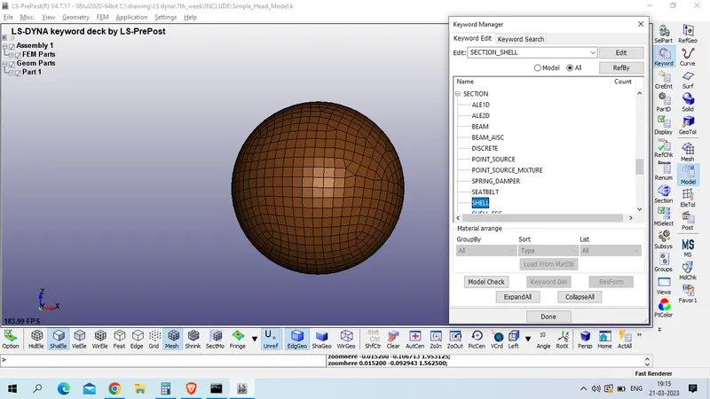
model and part >> keyword manager >> all >> section >> shell
Title : SECTION_SHELL
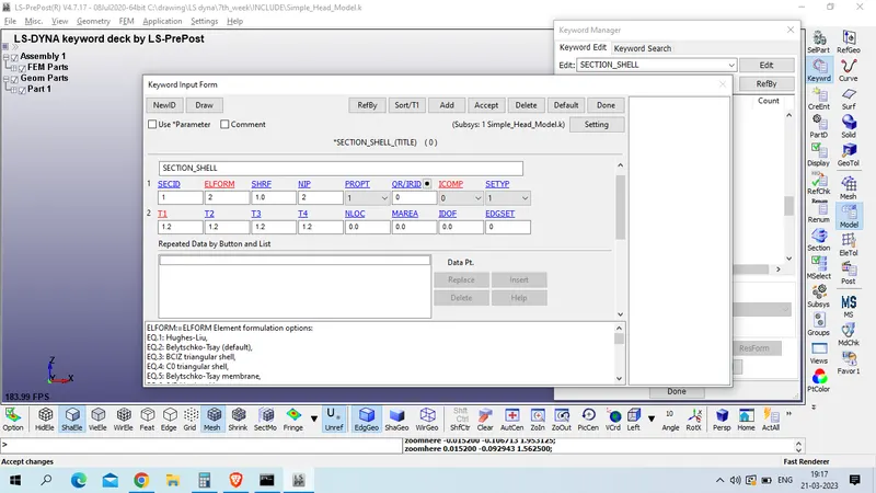
SECTID : 1
ELFORM : 2 (Belytschko-Tsay (default))
T1/T2/T3/T4 : 1.2
Rest setting as default
Accept >> done
now create material for this head model
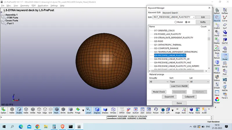
model and part >> keyword manager > all >> mat >> 024_PEICEWISE_LINEAR_PLASTIC
Now we will use kg-mm-ms unit system for this
mass - Kg
Length - mm
Time - ms
force - KN
Stress : GPa
Energy - KN-mm
Steel density - 7.83e-06 Kg /mm^3
Youngs modulus of steel - 2.07e+02 GPa
Possion's Ratio : 0.3
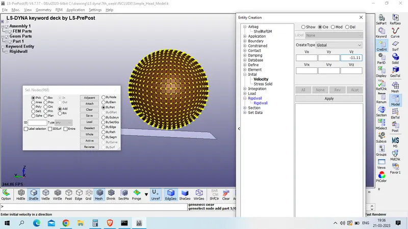
speed at 40 KM/h - 11.11 mm/ms
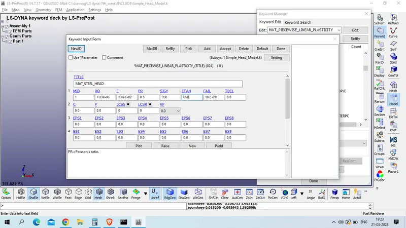
Title : MAT_STEEL_HEAD
MID - 1
Yield stress. - 350 GPa
Tangent modulus- 650 GPa
Accept >> done
now define hourglass card
model and part >> keyword manager >> all >> hourglass >> hourglass
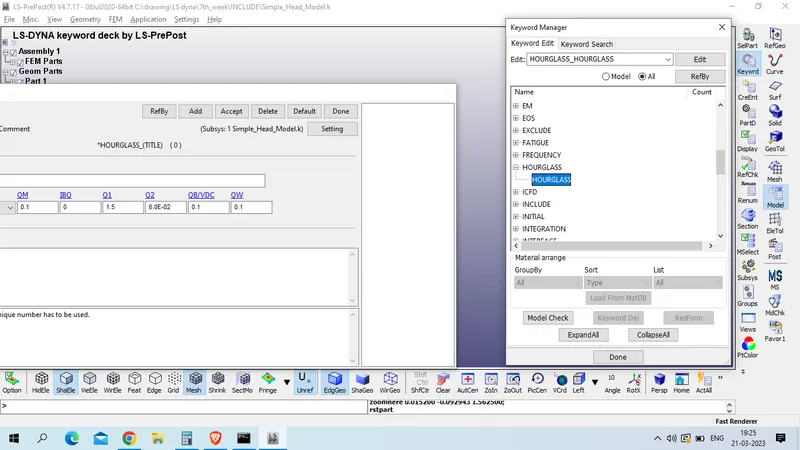
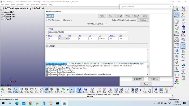
Title : HEAD_HOURGLASS
HGID : 1
IHQ:=Hourglass control type : 1
Accept >> done
now assign SECTION, MATERIAL and HOURGLASS to part
Model and part >> keyword manager >> model >> part >> part
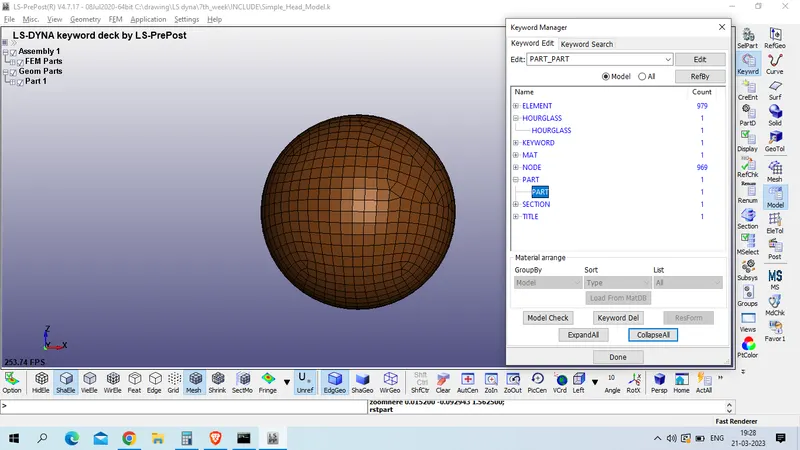
Title : HEAD_PART
PID : 5
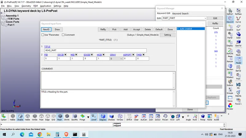
ACcept >> done
now create rigid wall
model and part >> create entity >> rigid wall >> rigid wall
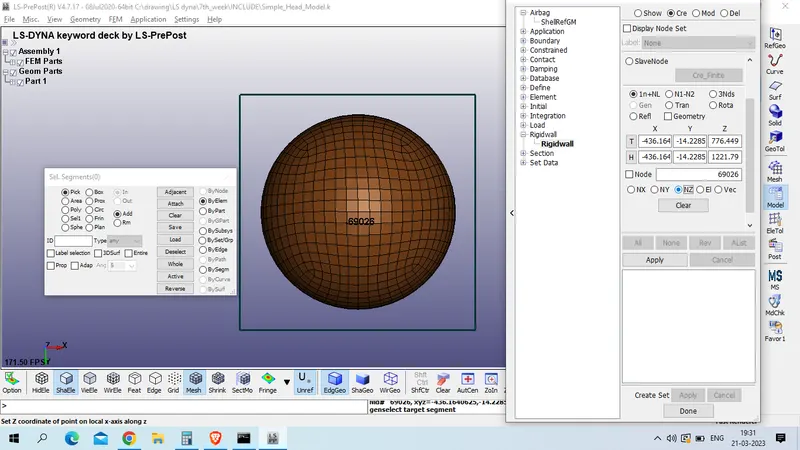
Click on create >> Planer >> Select a node >> Set Normal to z
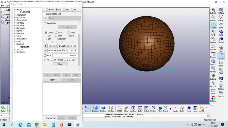
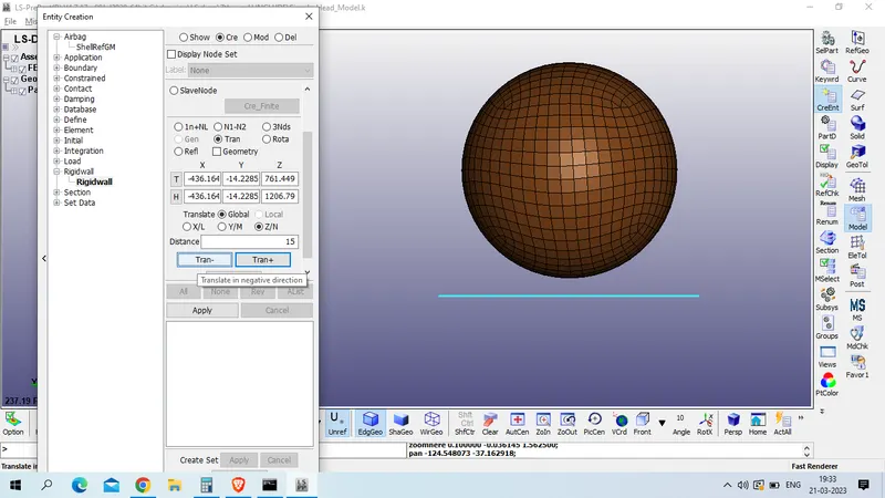
now translate this rigid body to 15 mm down
click on trans >> DISTANCE : 15 >> Trans - >> set Z/N
Apply >> done
Now create velocity to the head
model and part >> create entity >> INTIAL >> velocity
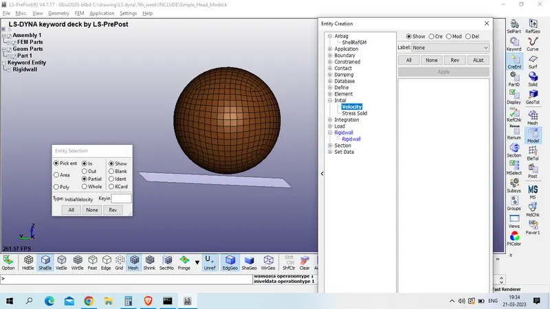
CLick on create >> select by part >> and select the head model
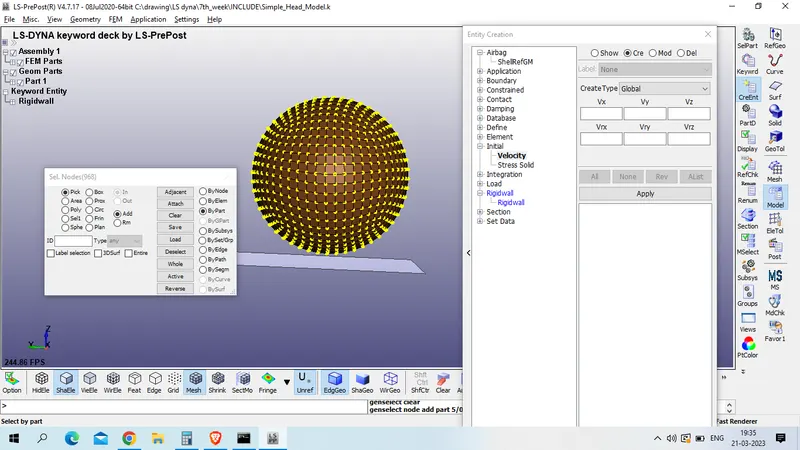
give velocity in z direction with magitude of 11.11 mm/ms in negative
apply >> done
Now create contact to the head model
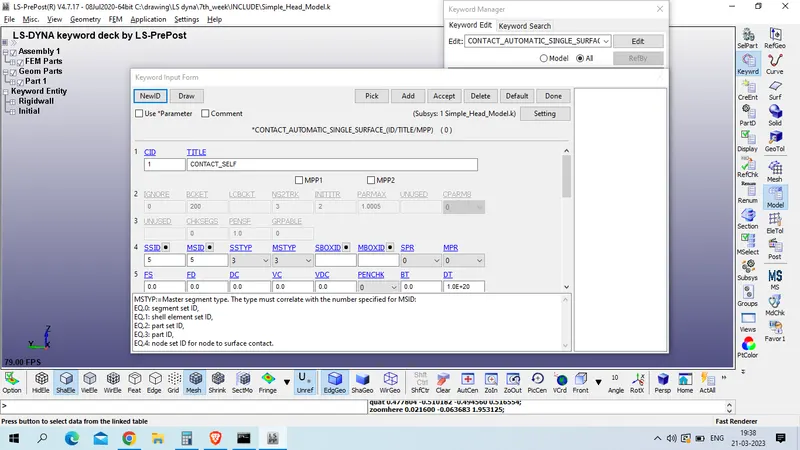
model and part >> keyword manager >> all >> contact >> AUTOMATIC_SINGLE_SURFACE
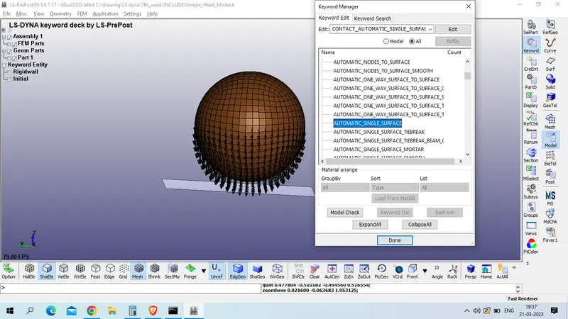
Title : CONTACT_SELF
CID : 1
make slave and master both as head part
FS & FD : 0.2
Accept >> done
NOw define control cart
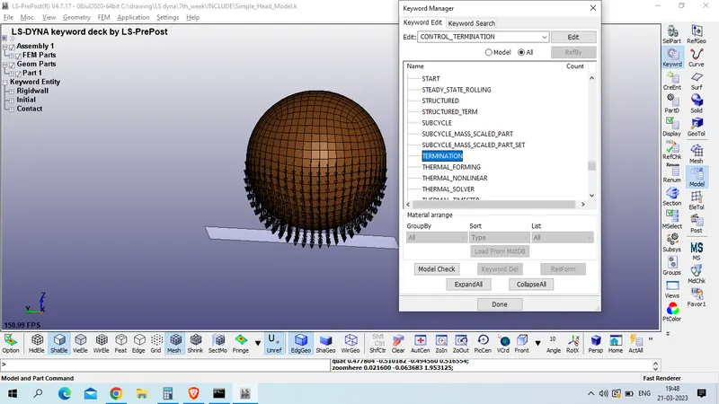
1. termination
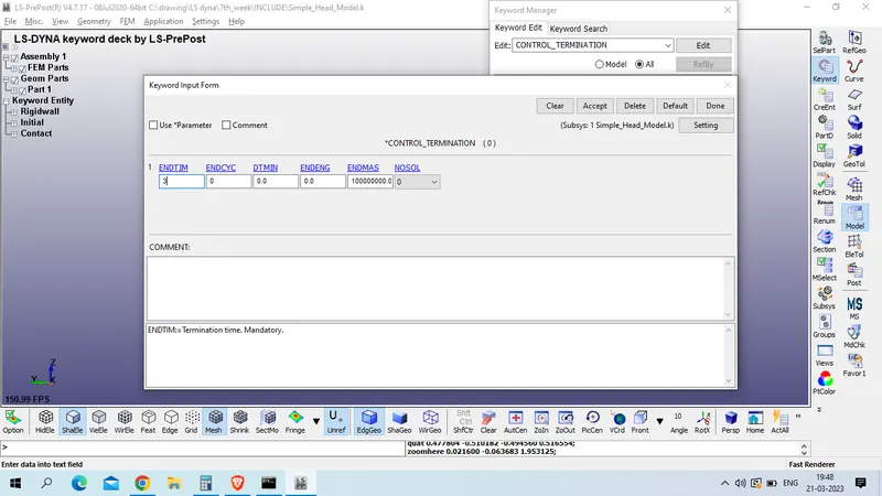
Model and part >> keyword manager >> all >> control >> termination
ENDTIM : 3
Accept >> done
now define database card
1. BINARY_D3PLOT
model and part >> keyword manager >> all >> database >> BINARY_D3PLOT
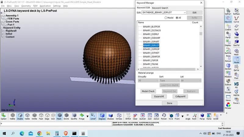
DT -0.2
Accept >> done
2.EXTEND_BINARY
Model and part >> keyword manager >> all >> DATABASE >> EXTEND_BINARY
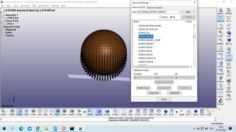
STRFLG : 1
Rest as default
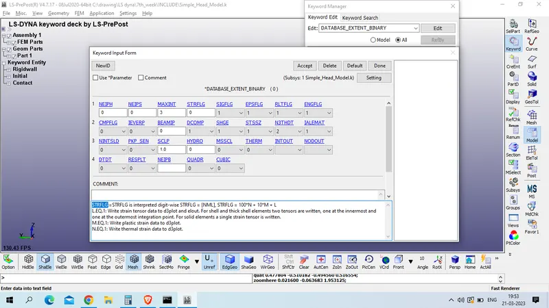
accept >> done
3. HIstoty NODE ID
Model and part >> keyword manager >> all >> DATABASE >> HISTORY_NODE_ID

Pick node from bottom ; Node id # 68789
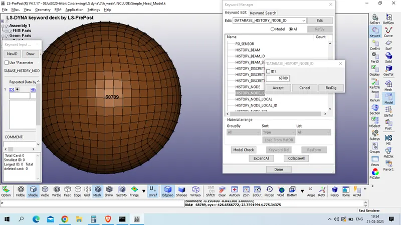
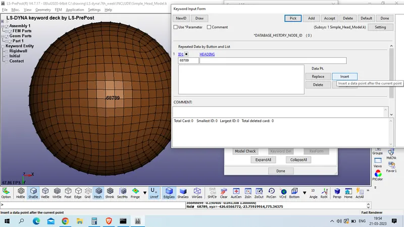
now insert >> accept >> done
4. ACSII_OPTION
Model and part >> keyword manager >> all >> DATABASE >> ACTII_OPTION
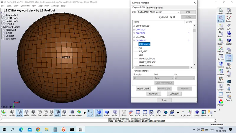
DEFAULT BINARY : 3
ELOUT - Element Output Data
GLSTAT - Global Statistics
MATSUM - Material Energies
NODOUT - Nodal Displacement/Velocity/Acceleration data
RWFORC - RigidWall Forces
all DT -0.2
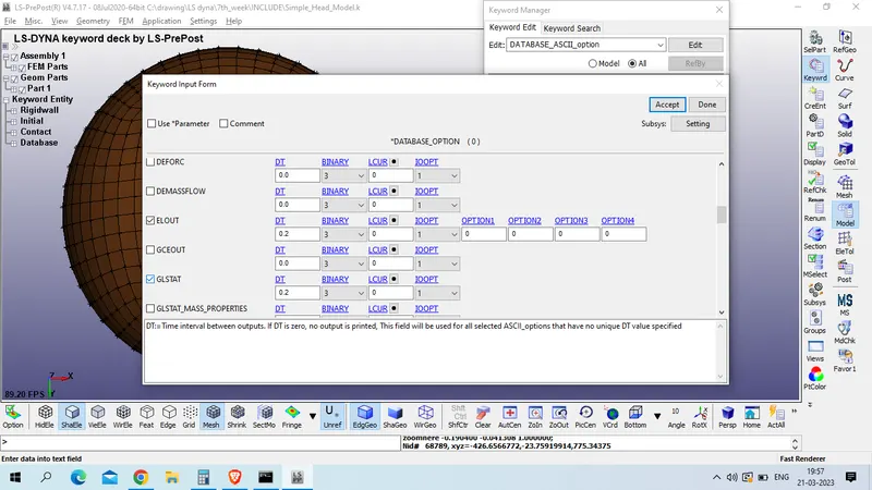
accept >> done
now check for keyword error
model check >> keyword check >> recheck
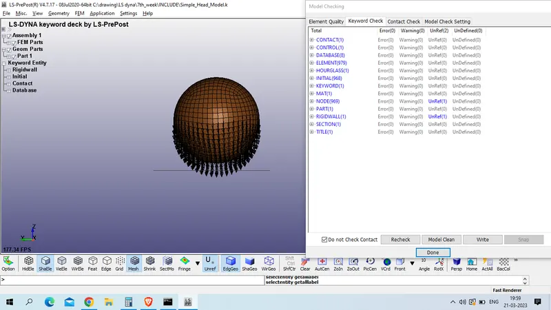
as we have zero keyword error we will save this file in diffrent folder and proceed for run
Results:
EFFECTIVE PLASTIC STRESS
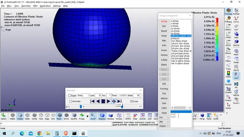
Graph of stress
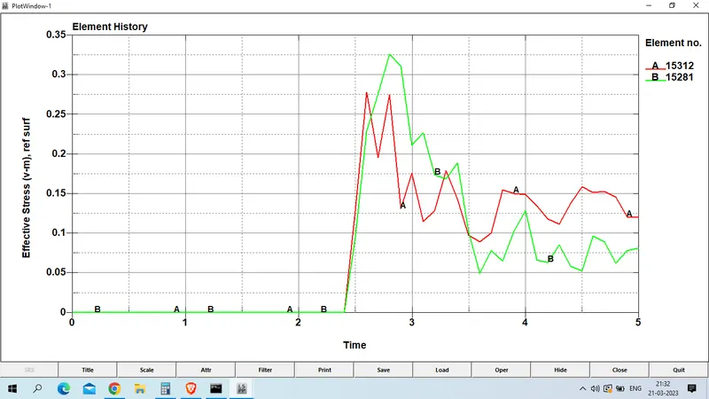
Max VOn Mises stress measure at element no 15821 is 0.326 GPa
Lower Ipt Plastic strain
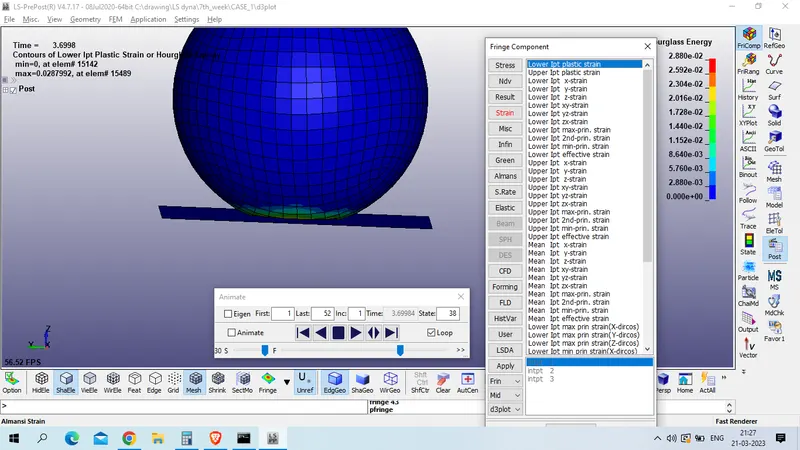
Plastic strain plot
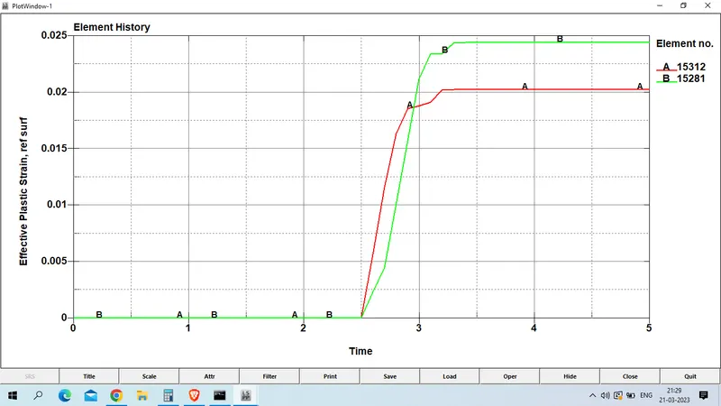
Max strain at element no 15821 is measure as 0.0244
Energy plot for case 1 is given below
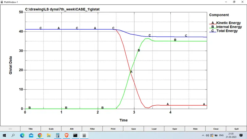
Calculation of HIC at node no 68789 is given below
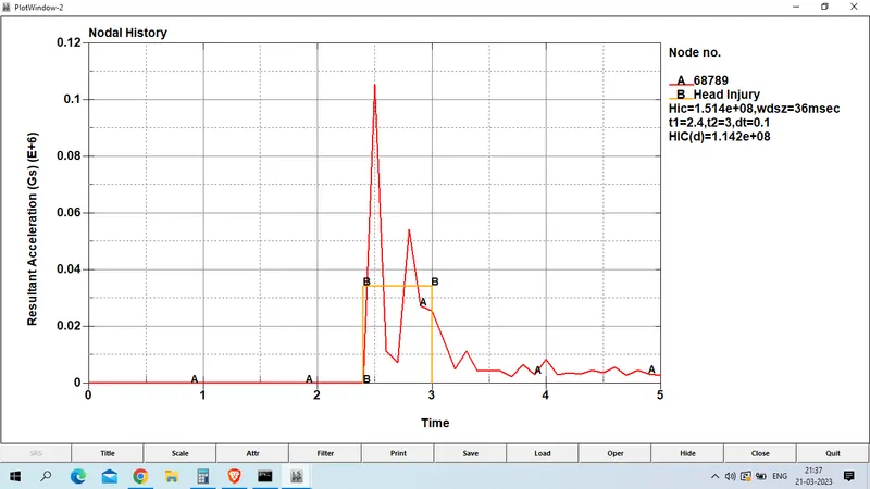
HIC(d) : 1.142E+08
Case 2: CHILD HEADFOAM IMpacted with rigid wall
open LS PrePost 
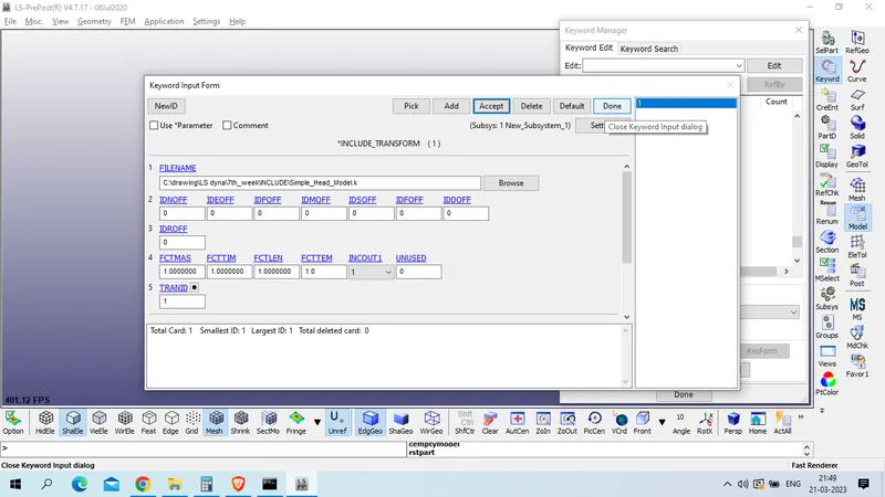
now we will refer include_tranformation cammand to for child head foam file
Model and part >> keyword manager >> all >> include >> transform
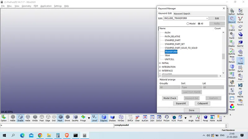
browse the file location in file name
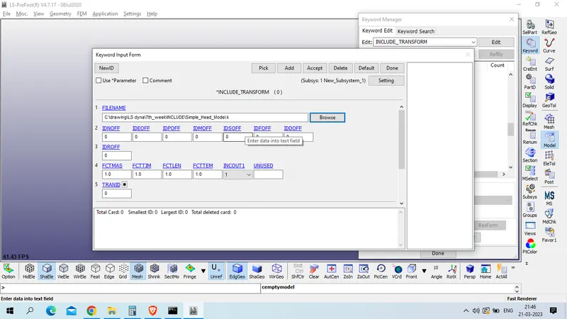
and create new define transformation
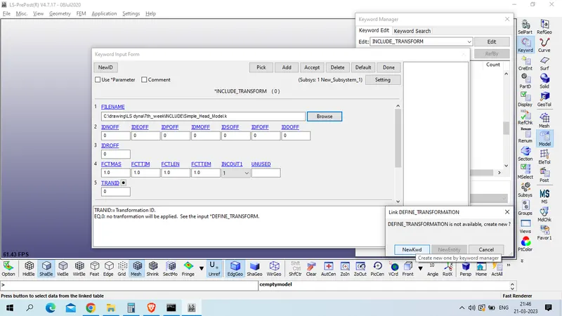
Title : HEAD_ROTATE
TRANID : 1
Option : Rotate
as we have to rotate the headfoam to 50 degree with ref. to global Y axis
put A2 : 1 and A7 :50
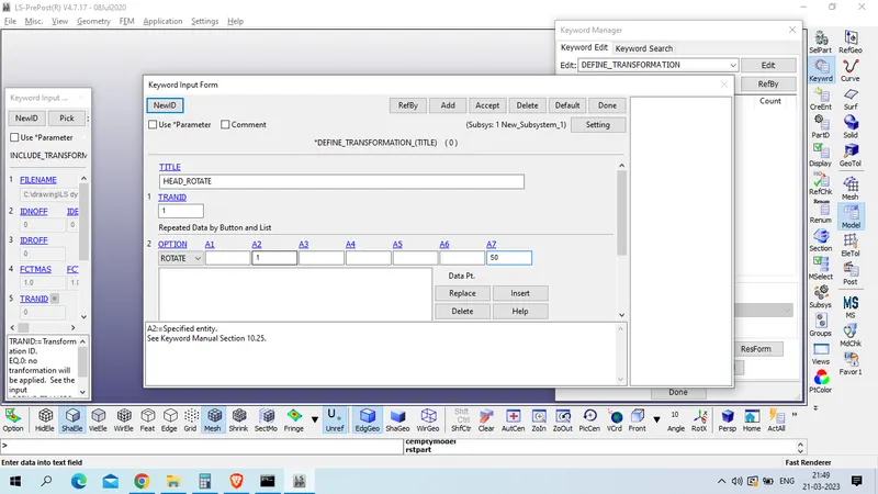
click on insert and accept
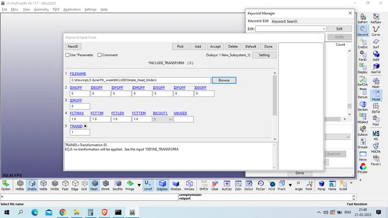
now accept include tranform file and done
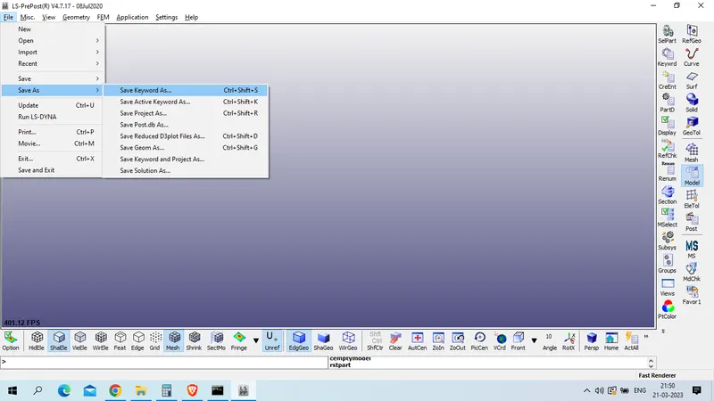
now save this file using
File >> save >> save keyword file
select the location and file name
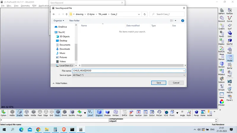
and save
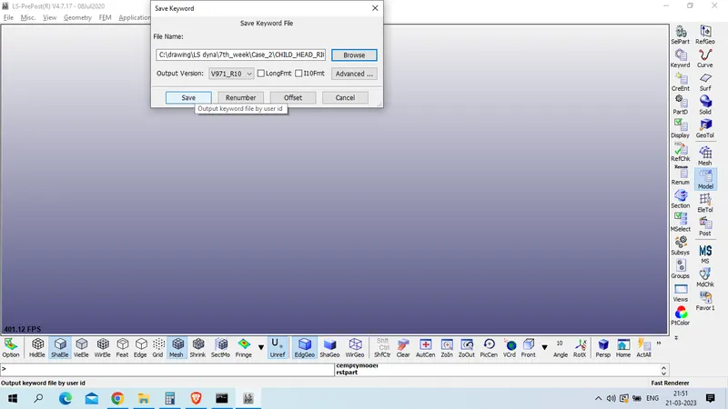
Now open this file in new LS PrePost page
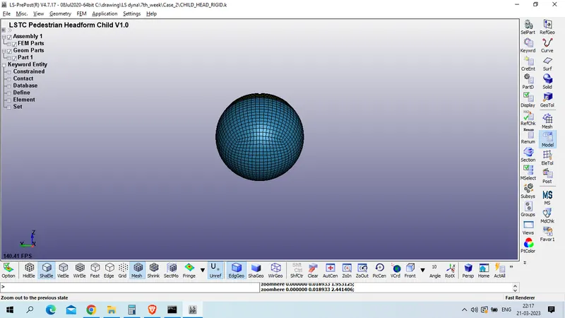
as we checked material card for this headfoam we found here also we are using Kg-mm-ms unit system as in case 1.
Now create part_set which include all parts of headfoam
model and part>> create entity >> set_data >> set_part
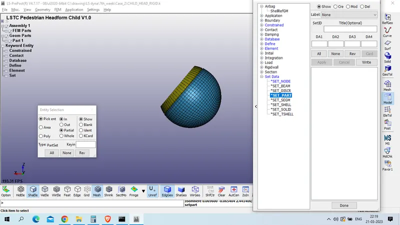
click on create >> select part by area >>
title : ALL_HEADFOAM_PARTS
SETID : 1
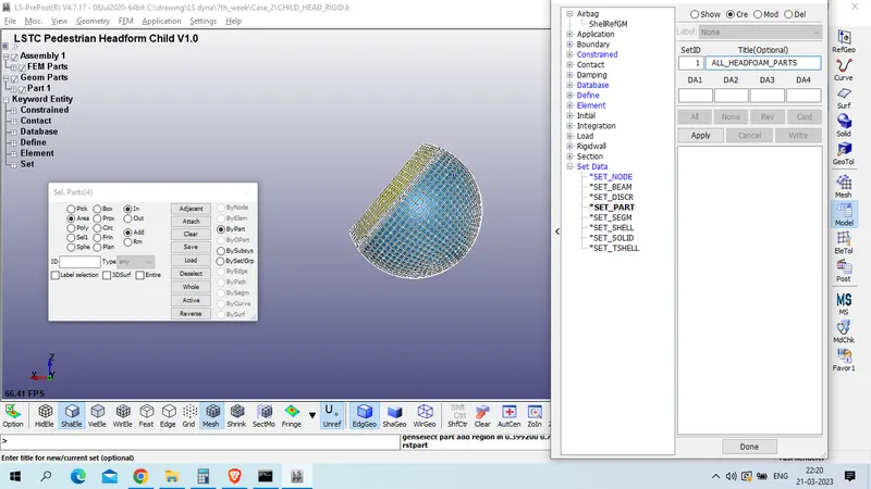
apply and done
as cheched all parts are pre defined with material and section id
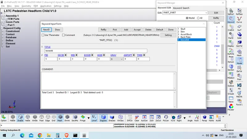
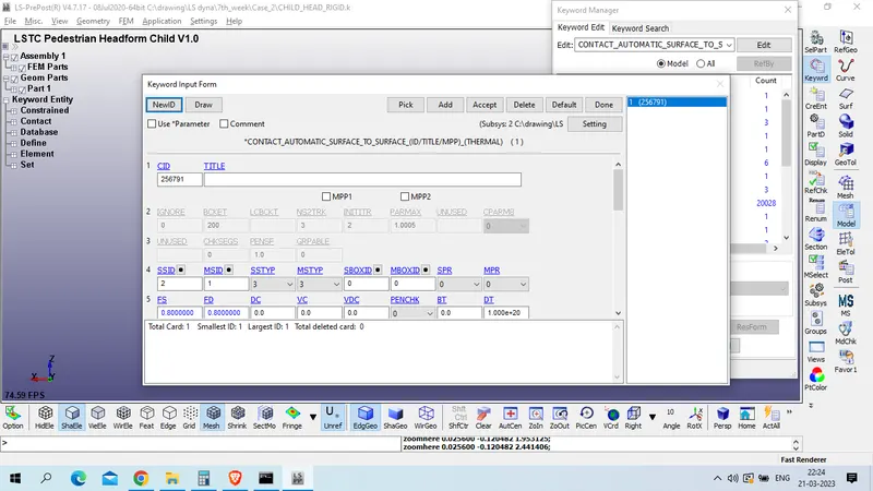
automatic surface to surface contact is also defined
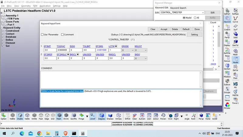
Control time step is also defined with TSSFAC:=Scale factor for computed time step as 0.9
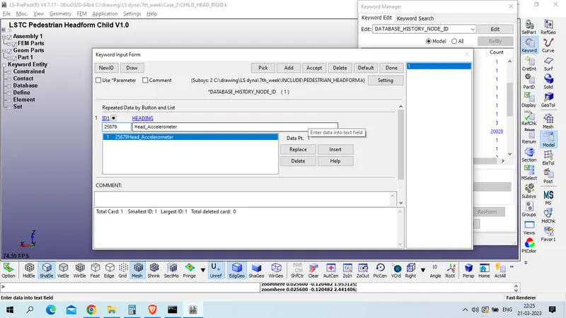
History node is pre defined for node id 25679 ,
now we will create rigid wall
Model and parts >> create entity >> rigid wall >> rigid wall
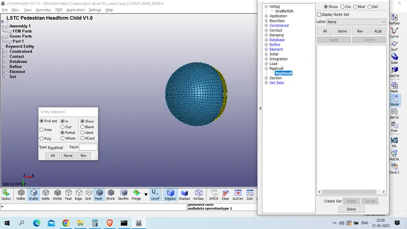
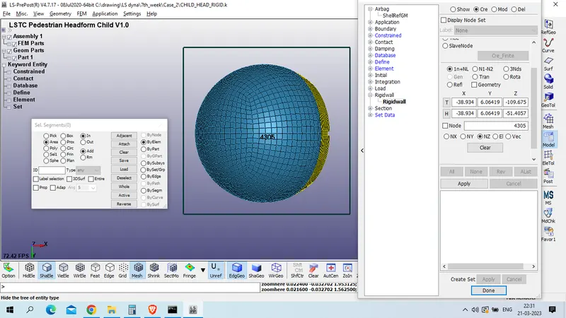
click on create >> planar >> select node on lower side >> click on NZ
now click on trans >> distance 15 >> click on Z/N >> trans -
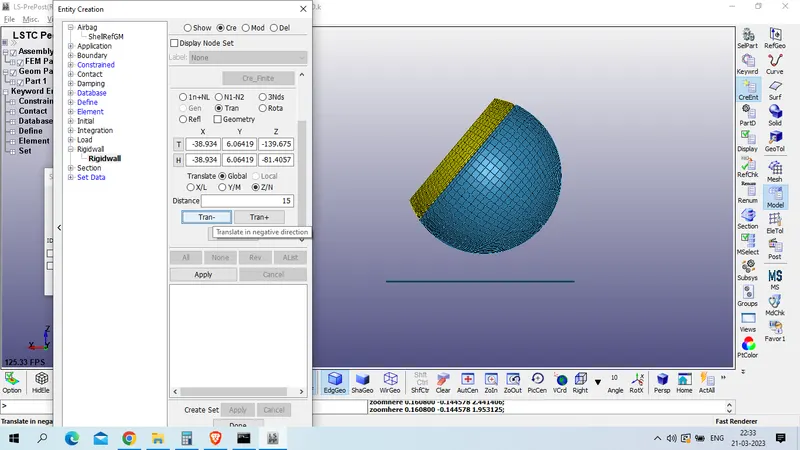
click on apply >> done
create velocity of 40 km/h to the head foam , as this head is moving in 50 degree inclined with global y axis .
so , z magnitude = 11.11 x sin(50) = 8.5107537
x magnitude = 11.11 x cos(50) = 7.141370
model and part >> create entity >> intial >> velocity
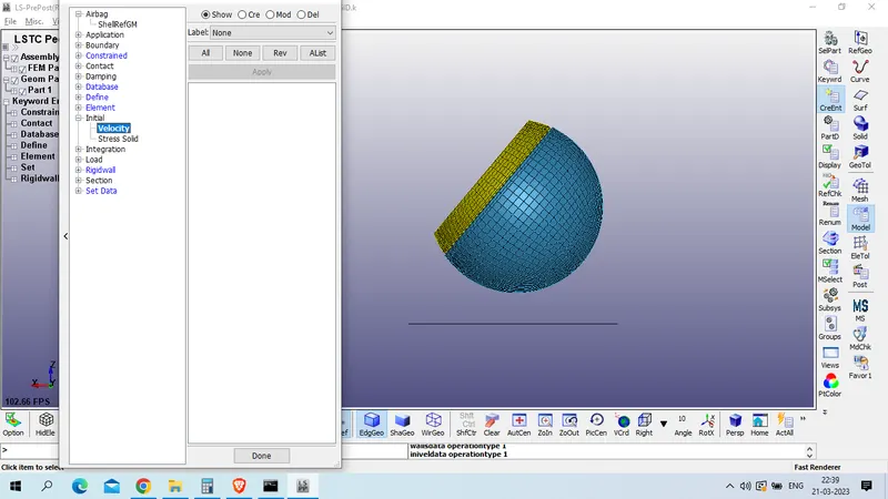
click on create >> select headfoam by area >>

put x and z magnitude as calculated with negative sign .
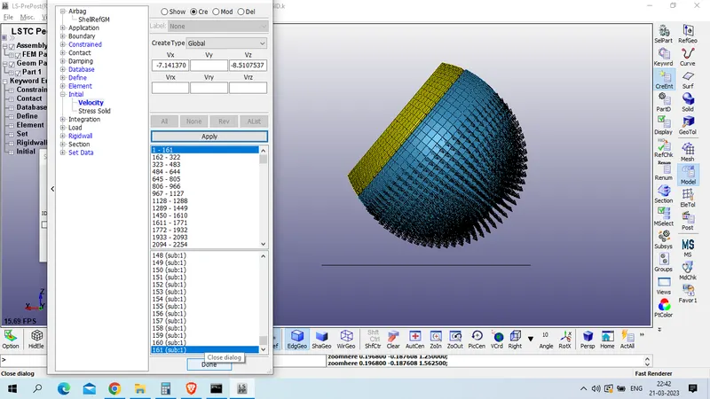
click on apply and done.
now create control_termination card for end the simulation , ENDTIM =20 ms
model and card >> keyword manager >> all >> control >> termination
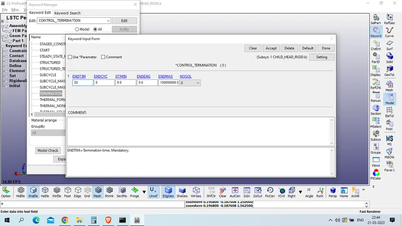
now define database card to this ,
model and part >> keyword manager >> all >> database >> BINARY_D3PLOT
DT :0.5
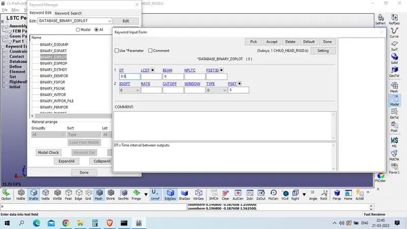
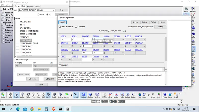
2. EXTEND_BINARY , STRFLG : 1, rest as default
3. ASCII_OPTION
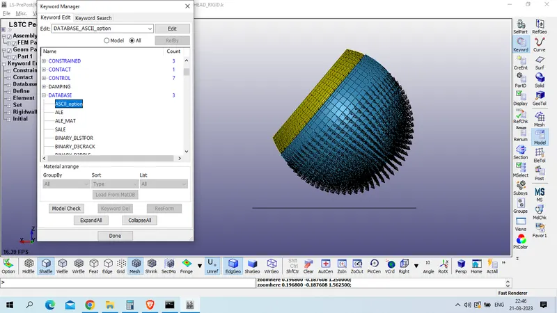
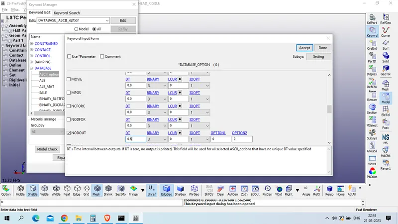
ELOUT - Element Output Data
GLSTAT - Global Statistics
MATSUM - Material Energies
NODOUT - Nodal Displacement/Velocity/Acceleration data
RWFORC - RigidWall Forces
ALL DT ; 0.5, BINARY : 3
accept >> done
now we will for keyword error
model checker >> keyword check >> recheck
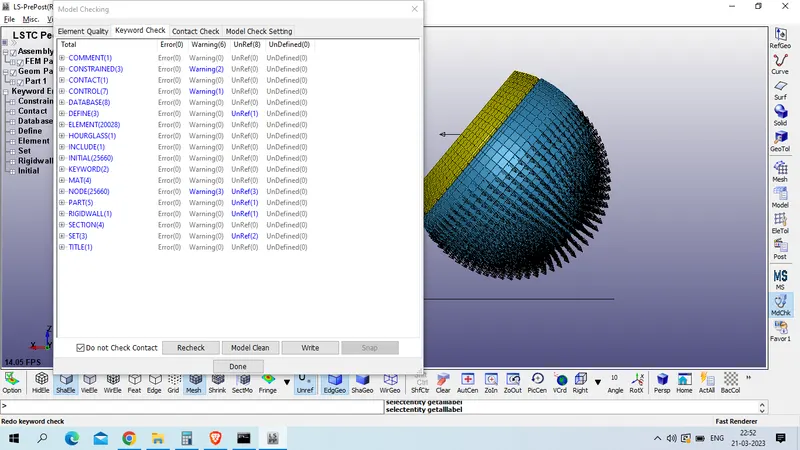
as we have zero error we will save this file .
file >> save as >> save keyword as
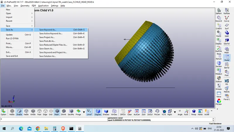
select only main file ; uncheck the refered file which was include
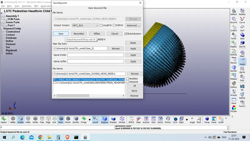
click on save
now run for the simulation
File >> run LS DYNA
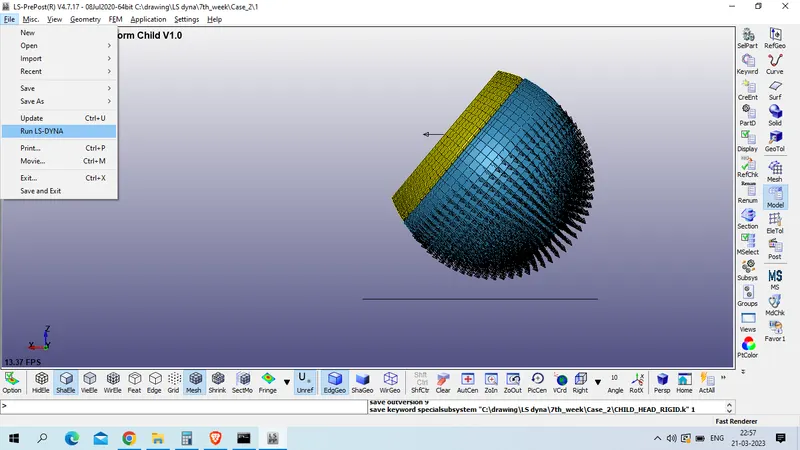
select file >> run
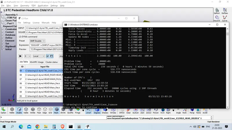
Results:
1. Von Mises Stress
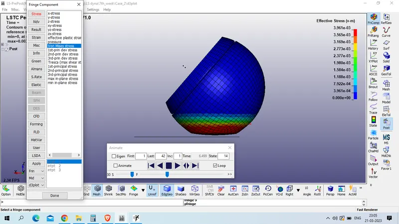
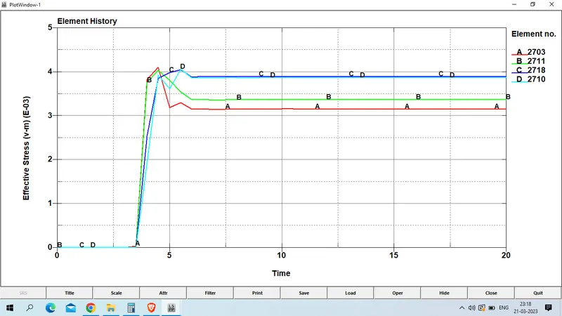
Plot for von mises stress at element no 2703, 2711 as given below
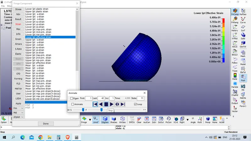
2. Lower IPt Effective strain
we observed max stress (VON_MISES) at element no 2703 which is 0.00411 GPa.
Plot for efective plastic strain at element no 2703, 2711
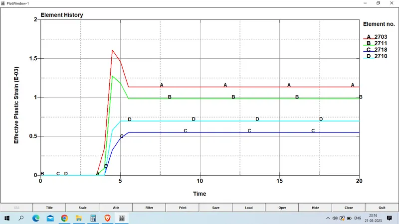
we observed that max stain was 0.00161 on element no 2703.
3. Resultant acceleration experiance by node 25679 is as given below
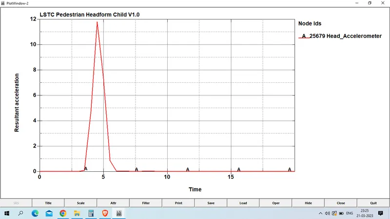
max acceleration received at 4.5 ms which is 11.8 mm/ms^2 at node id 25679.
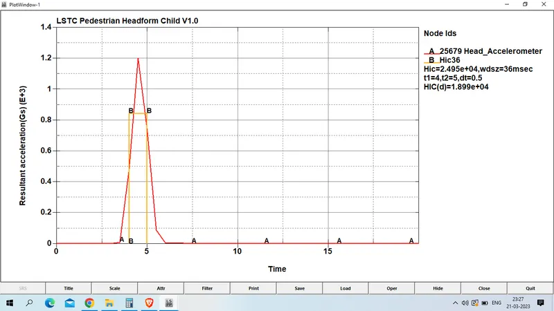
4. HIC 36. we had received hic 36 at node 25679 which is 1.89E+4
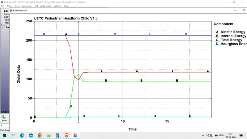
5. Global enery Plot is as given below
3. Case 3 : child headfoam impacted with mesh hood model
Open new LS PrePost page as in previous case and open mesh hood model.
file >> open >> LS DYNA KEYWORD FILE
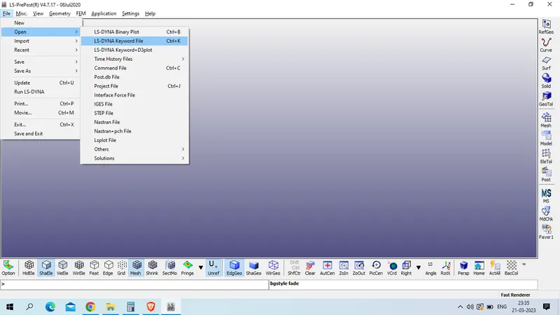
select hood mesh model and open
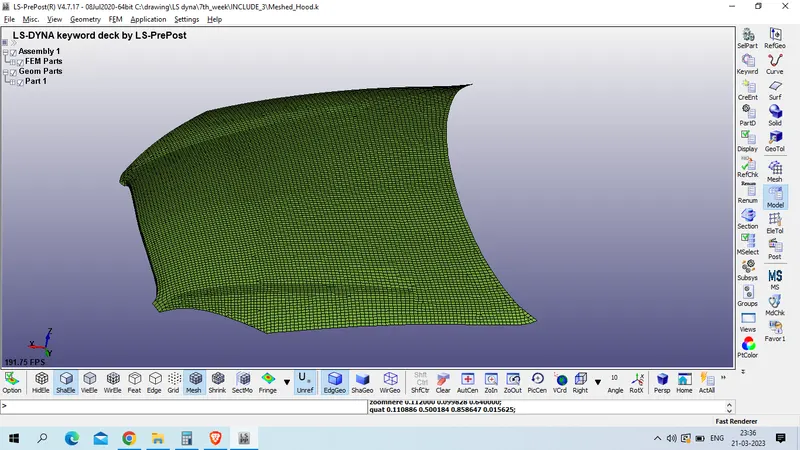
checked the model as it does not have section and material card we will define it 1st
model and part >> keyword manager >> all >> section >> shell
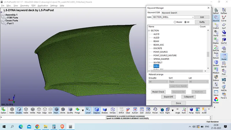
Title : SECTION_SHELL
SECID : 10
T1/T2/T3/T4 : 1.2
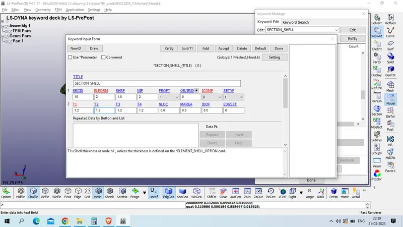
accept >> done
for material .
model and part >> keyword manager >> all >> mat >> 024_PEICEWISE_LIINEAR_PLASTIC
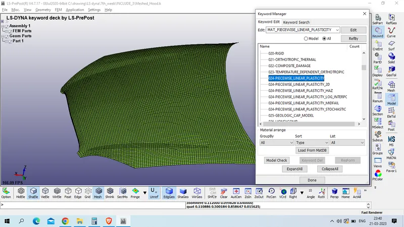
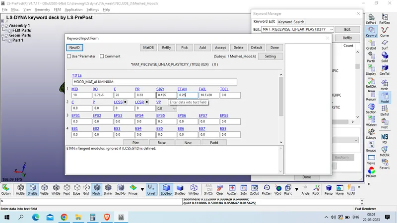
Title : HOOD_MAT_ALUMINIUM
MID : 10
Density of aluminum : 2.7E-6 Kg/ mm^3
Young's modulus of aluminium : 70 GPa
Poission's ratio : 0.33
Yield stress : 0.125 GPa
Tangent modulus : 0.25 GPa
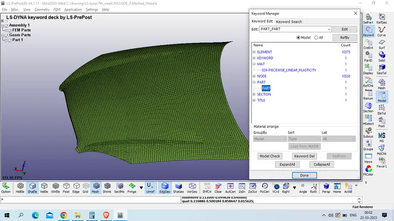
Now assign this material and section to the part
Model and part >> keyword manager >> model >> part >>part
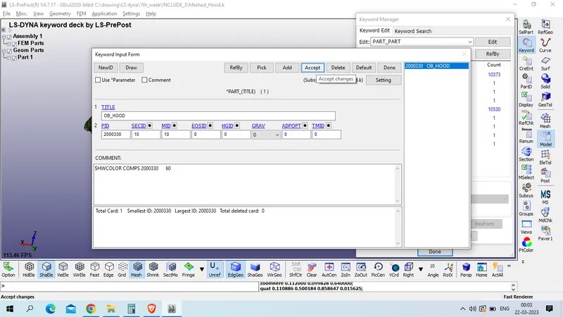
Title : OB_HOOD
PID : 2000330
now save this hood model to the folder
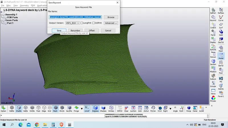
now open new LS PREPOST
now refere the mesh hood model using include cammand
model and part >>keyword manager >> all >> include >> include
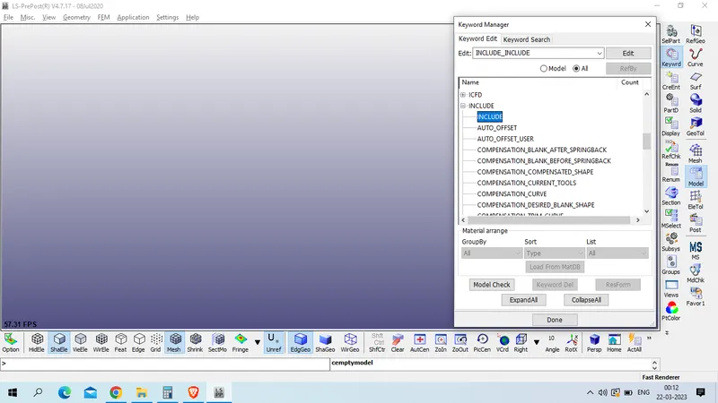
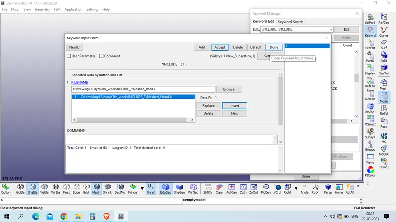
select the mesh hood file path >> insert >> accept >> done
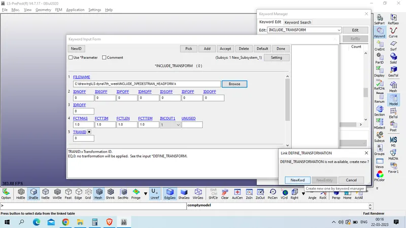
now refer child_headfoam using include >> transform
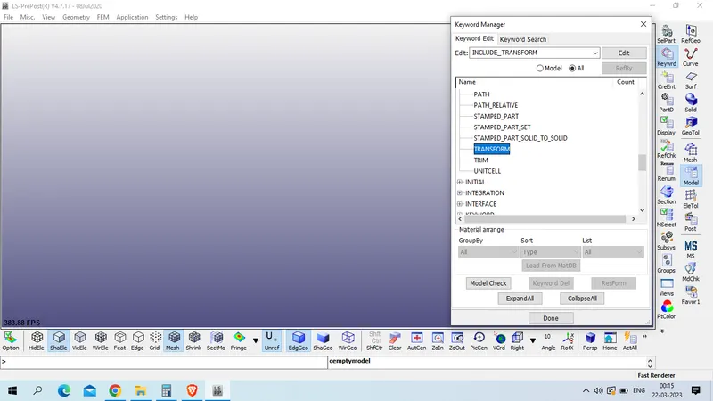
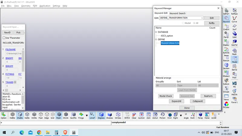
select file in file name >> Transformation ID >> create using new create
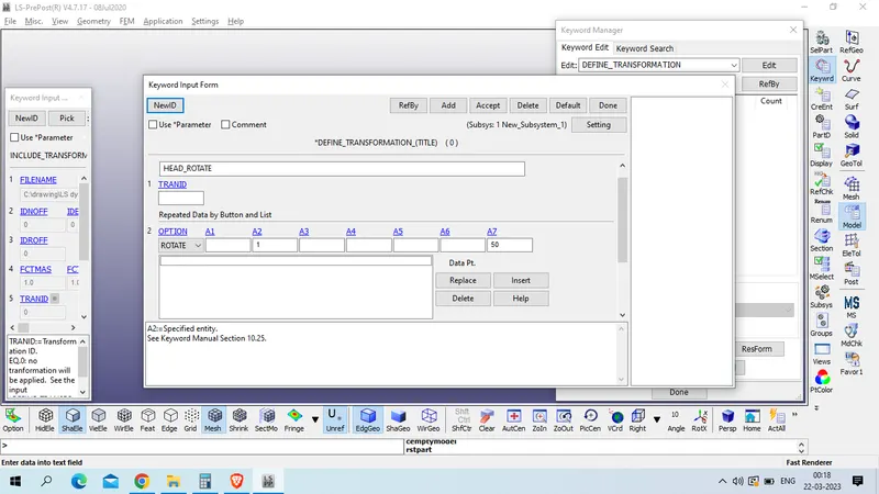
Title : HEAD_ROTATE
TRANID: 1
option : Rotate
A2 : 1 and A7 : 50
insert >> accept >>
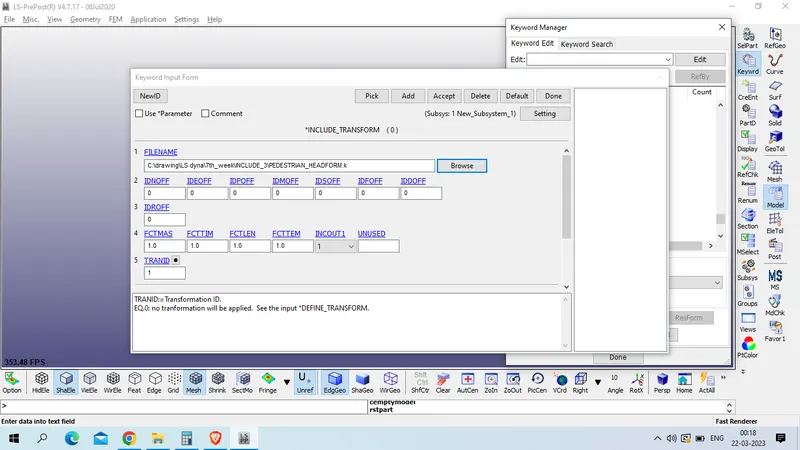
accept transform file >> done
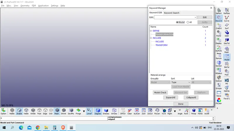
now save this keyword file in new folder
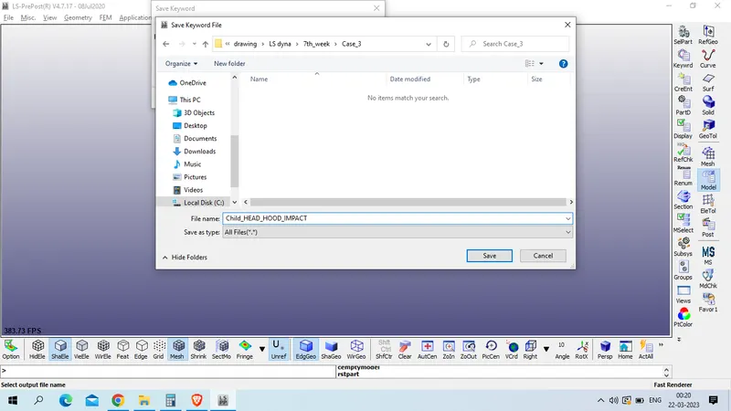
give proper name >> save
now open new LS prepost and open this file
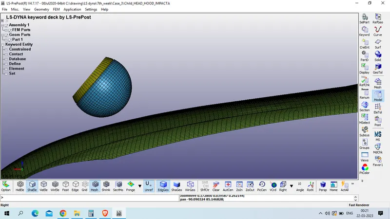
now 1st define boundary condition to fix the outer node of hood model
Model and part >> create entity >> boundary >> spc
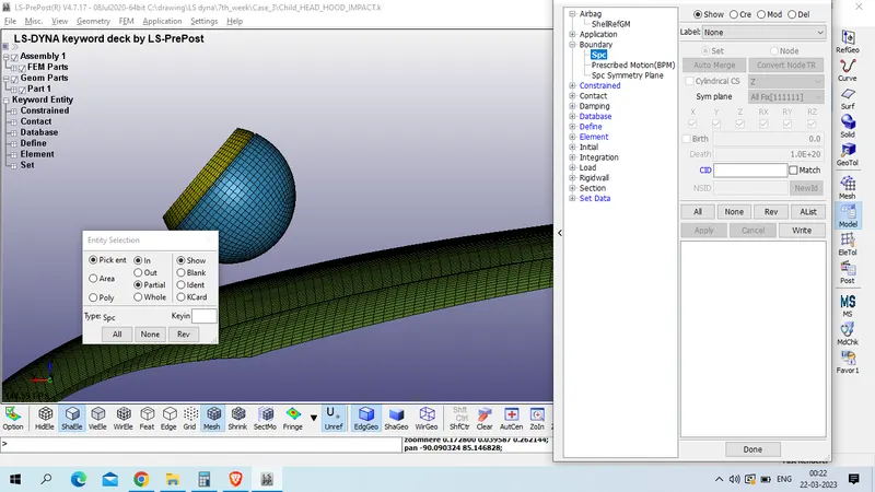
click on create >> select outer node by as given below
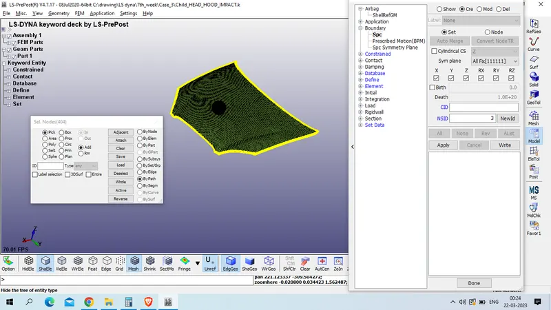
constrain all translation and rotation motion to these node by checking all X,Y,Z,RX,RY,RZ
apply >> done
and rename this set using model and path >> keyword manager >> model >> set >> node
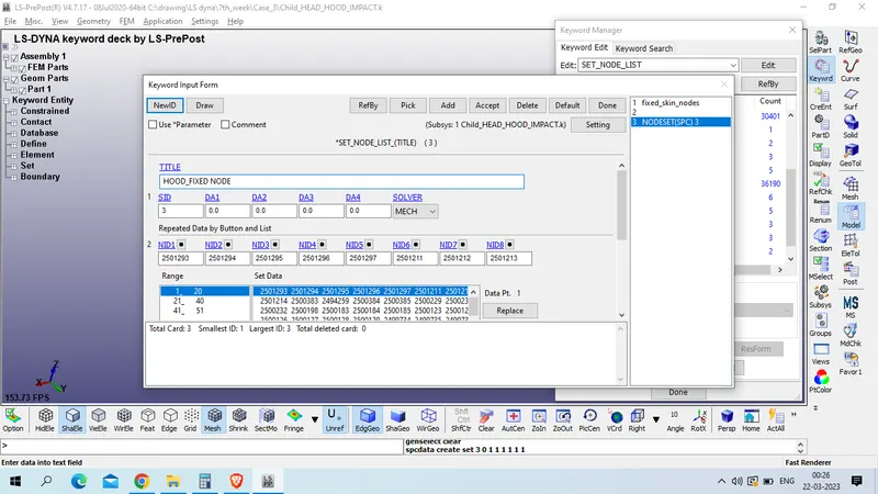
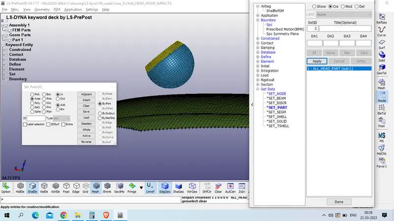
now create part_set for all part of head included in 1 set
model and part >> create entity >> set_data>> set_part>> create >> select all head foam part by area
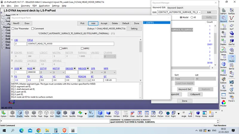
now create contact between hood model and headfoam model slave as headfoam and master as hood.
model and part >> keyword manager >> all contact >> AUTOMATIC_SURFACE_TO_SURFACE
Title : CONTACT_HEAD_TO_HOOD
CID : 2
FS and FD : 0.2
now define velocity as case 2 with x direction 7.14137 and z direction 8.5107537 mm/ms in negative magnitude
Model and part >> create Entity >> intial >> velocity >> create >>select all head_part by area selection method
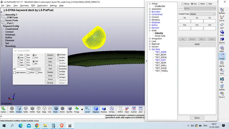
apply >> done
now we will define termination card
model and part >> keyword manager >> all >> control >> termination >>ENDTIM : 20
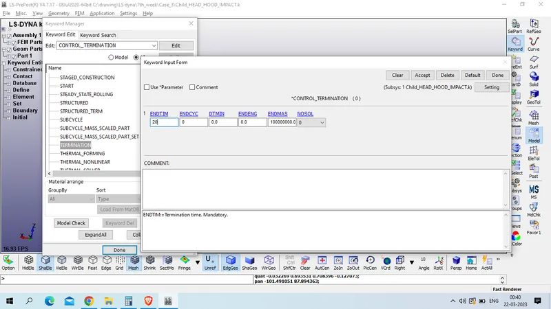
define database card
1. BINARY_D3PLOT
model and part >> keyword manager >> all >> database >>BINARY_D3PLOT
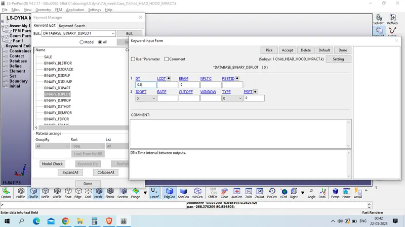
2. EXTEND_BINARY >> STRFLG :1, rest as defualt setting
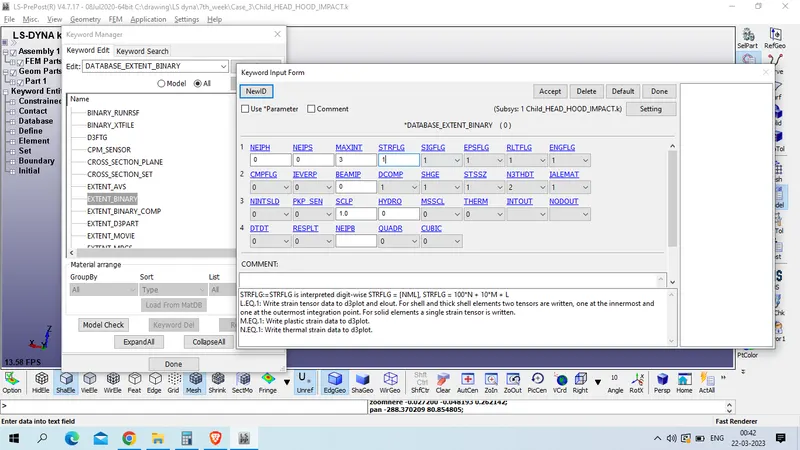
3. ASCII_OPTION
DEFAULT_BINARY : 3
ELOUT - Element Output Data
GLSTAT - Global Statistics
MATSUM - Material Energies
NODOUT - Nodal Displacement/Velocity/Acceleration data
RCFORC - Resultant Interface Forces
RWFORC - RigidWall Forces
ALL DT -0.5
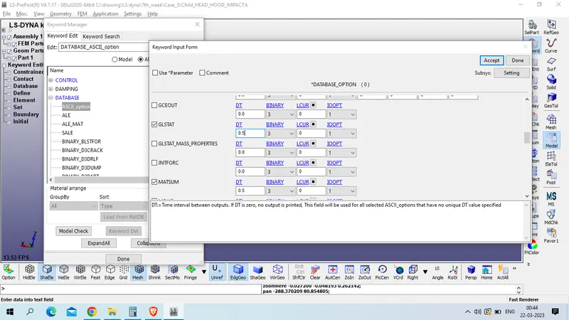
now check for model keyword error
model checker >> keyword check >> recheck
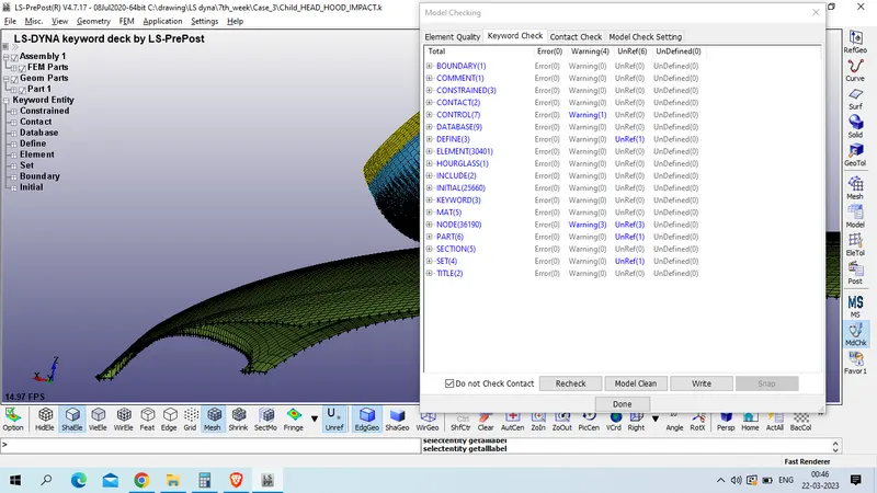
as we have zero keywrod error now we will save this file
file >> save As >> save keyword file as
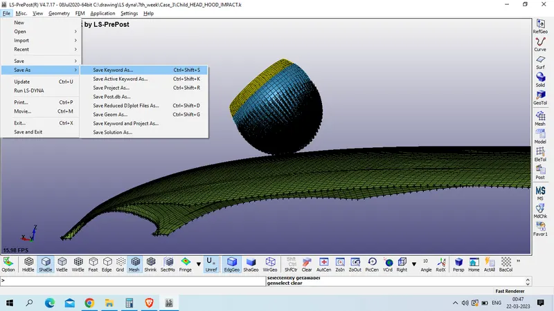
select only main file which we created >> save
now run for simulation
file >> run LS DYNA
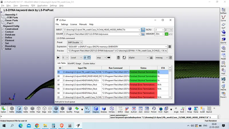
select file >> run
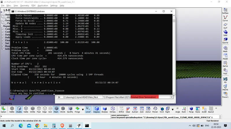
Result :
Von Mises stress
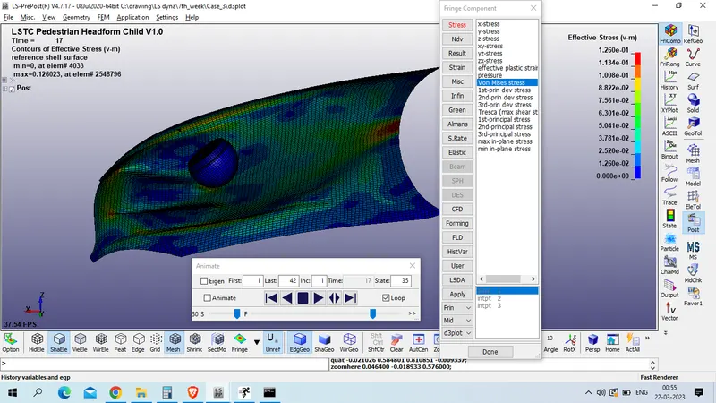
Plot for stress (Von Mises ) at element no 2701 is given as below
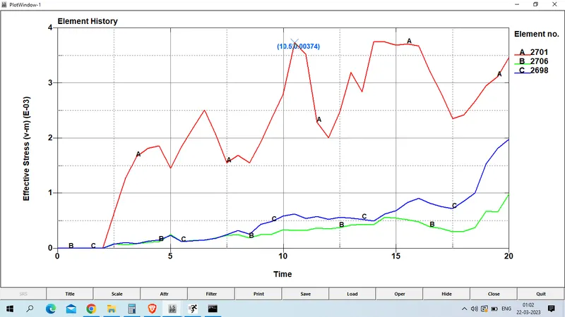
The maximum stress received at element no 2701 is 0.00374 GPa.
2. Lower Ipt Platic strain
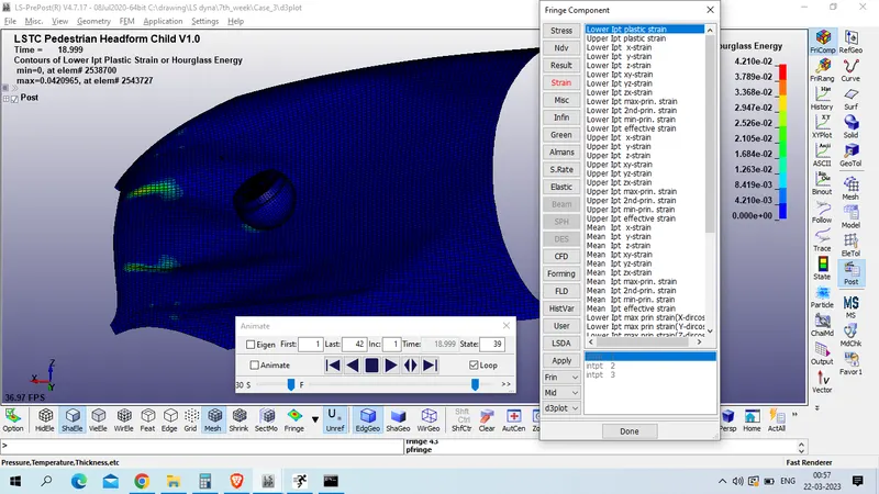
Plot of effective plastic strain is as given below for element no 2701
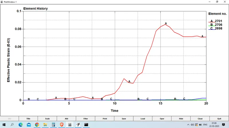
Maximum strain of head at element no 2701 is 8.53E-05.
3. resultant acceleration experiance by the node 25679 is as given below
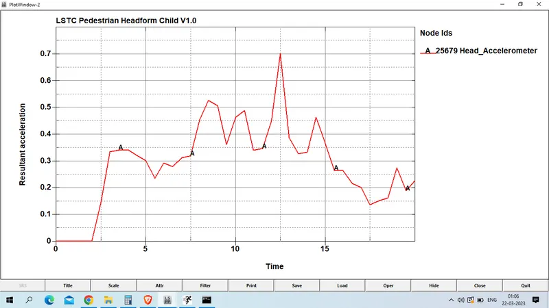
The maximum acceleration experiance by node 25679 is 0.702 mm/ms^2 at 12.5 ms.
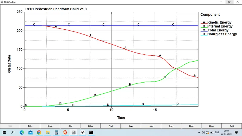
4. Energy plot
the kinetic energy , interal enery , total enery and hourglass energy plot is as given below
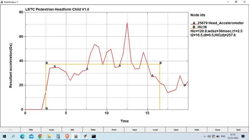
5. HIC 36 at node no 25679 is given as below
HIC(d) : 257.6
conclusion :
the comparison of HIC 36, STRESS and strain is as given below
| Case 1 | Case 2 | case 3 | |
| HIC | 1.14E+08 | 1.89E+04 | 257.6 |
| STRESS (Gpa) | 0.326 | 0.00411 | 0.00374 |
| STRAIN | 0.0244 | 0.00161 | 8.53E-05 |
as we know that in 1st case we had taken only outer shell which is made of steel whose mechanical properties such as young modulus , yeild tress are much higher that actual head, so that we had experinace maximum stress in cases 1 and maximum strain . there is no significant deformation in the simple head geometry. That’s why the HIC values are too high
in case 2 we had used child head foam which is reprentation of actual head with related material but we had used rigid wall for impact , so that we had used plastic linear platic material also . rigid wall is undeformable so the total stress is transferred to the head and deforms the head foam geometry severely the HIC values are lower than case 1
in case 3 we had used actual head foam as in case 2 and we had used actual hood model with aluminium material as in real life uses , as we had used thin aluminium material with linear peicewise material which is easly deformable while in case of accident. thus we had experiance lowest strain which is also neglegible and hic value is also very less which is 257 only