Week-7 Head Impact
AIM:-
To perform Head impact analysis On child pedestrian head Using LS-Dyna and Calculate Head Injury Criterion (HIC) value in different case setups.
INTRODUCTION:-
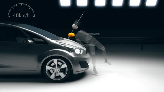
Pedestrian safety simulation is a part of vehicle safety engineering. This study focuses on car and pedestrian interaction. The main focus of this is to reduce pedestrian injury in case of an accident (head injury, leg injury, etc). Usually, these tests are performed in the lower velocity range from 20-40KmpH. HIC(Head injury criteria/coefficient) is a measure of the likelihood of the head injury caused due to the impact after an accident. This is basically a measure of average acceleration during a small interval of the crash.

Currently in India, Automotive Indian Standard (AIS) 100, Amendment 1 is used to evaluate the performance of vehicles against pedestrian safety. This standard has been harmonized from the international evaluation standard Global Technical Regulation No. 9 (GTR 9), whose purpose is to bring about an improvement in the construction of the fronts of vehicles and, in particular, those areas which have been most frequently identified as causing injury when in collision with a pedestrian or other vulnerable road user. The tests required are focused on those elements of the child and adult body most frequently identified as sustaining an injury, i.e. the adult head and leg and the child's head. To achieve the required improvements in the construction of vehicles, the tests are designed in such a way that they will represent the rear world accident scenario.
HEAD INJURY CRITERION:-
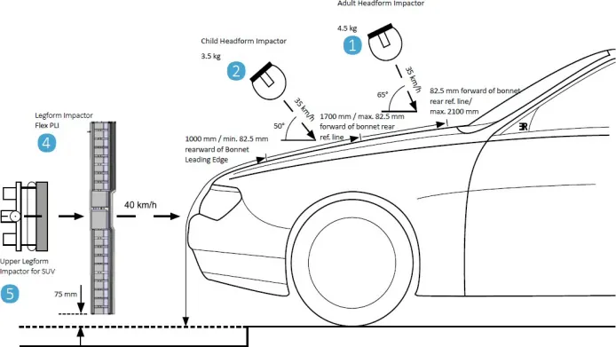
Head foam impactors are used to test the behavior of vehicle structures such as the hood. In a pedestrian-vehicle impact, the kinematics and severity of pedestrian injuries are affected by the impact locations on the vehicle and body velocities after impact. The objective of this project is to analyze the pedestrian kinematics in a Pedestrian-Car accident scenario and determine the Head Injury Criteria (HIC) from the head resultant acceleration, for head impacts on the vehicle hood
The head injury criterion (HIC) is a measure of the likelihood of head injury arising from an impact. The HIC can be used to assess safety-related to vehicles, personal protective gear, and sports equipment.
Normally the variable is derived from the measurements of an accelerometer mounted at the center of mass of a crash test Dummy's head when the dummy is exposed to crash forces.

where t1 and t2 are the initial and final times (in seconds) chosen to maximize HIC and Acceleration is measured in gs (standard gravity acceleration). The time duration, t2 – t1, is limited to a maximum value of 36 ms, usually 15 ms.
This means that the HIC includes the effects of head acceleration and the duration of the acceleration. Large accelerations may be tolerated for very short times.
At a HIC of 1000, there is an 18% probability of a severe head injury, a 55% probability of a serious injury, and a 90% probability of a moderate head injury to the average adult.
CASE-1: SIMPLE HEAD IMPACT ON RIGID WALL:-
Geometry:
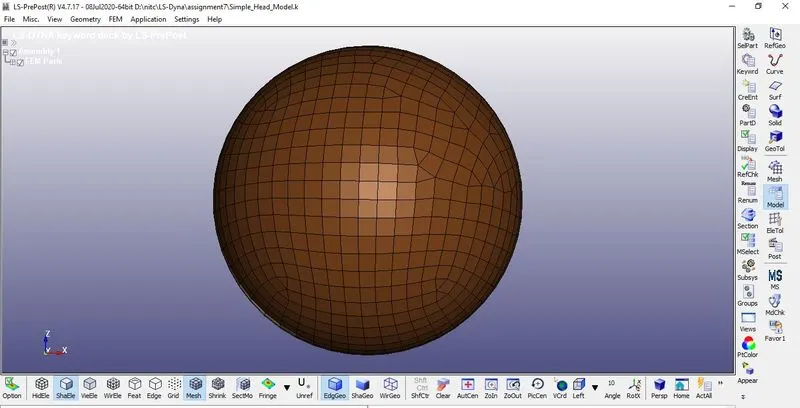
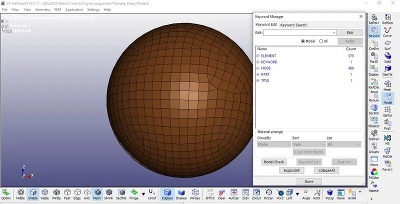
1. A simple head Geometry Keyword file is Imported and the Model is verified using Model info
2. The GiVen Simple head Model has meshed with Shell elements.
3. The Unit Kg/mm/ms is followed throughout the Analysis
Rigid Wall:-
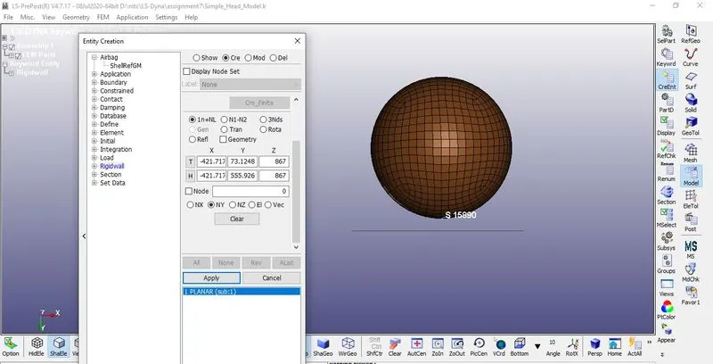
1. A Rigid wall is created Normal to the Z-axis by Create entity >Rigid wall > Planar option.
2. The Rigid wall is Displaced 15mm normal to the Z-axis
Section Creation:-
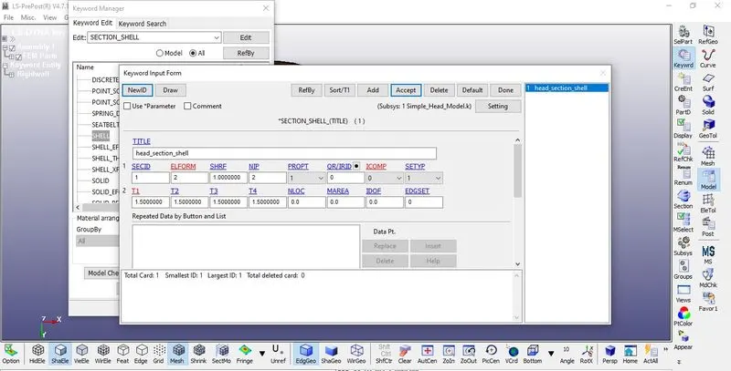
1. For Defining Section Go to Keyword manager > All > Section > Shell
2. For the Simple head Section_SHELL is created because it has meshed with simple 2D elements.
3.The element Formulation is Given as 2 And the thickness of 1.5mm is Assigned.
Material Model:-
1. For Defining materials go to Keyword Manager > All> MAT > Select the Material card and define the material properties like density, Young’s modulus, Poisson’s ratio.
2. For the Simple Head MAT_Elastic Material Card is assigned with the Properties Of Silicone
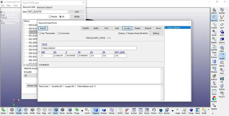
Massdensity(RO)=2.300e-06 kg/mm3
Young'sModus(E)=50Gpa
Poisson'sratio(PR)=0.49
Specifying the Material and Section ID to the respective part IDs.
1. In parts, we basically assign material and sections with their proper ID for every part individually.
2.Assign the Section-Id and Materials Individually as Part-1.
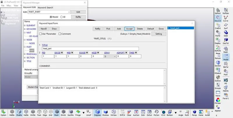
3. For Creating part Go to Keyword manager> Model > Part and assign the Materials and Sections of the Simple head
Boundary Condition:
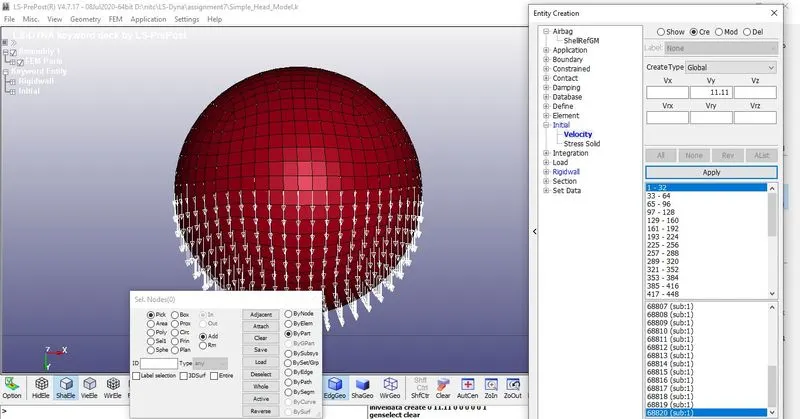
1. Initial velocity Is defined to the Simple head By Keyword manager > New > Initial > Velocity. select the Nodes By part Apply
2. An velocity of -11.11 mm/ms (40kmph) Is assigned to all the Nodes in a Simple head.
CONTACT INTERFACE:-
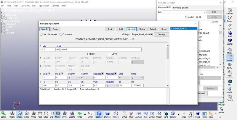
1.As the wall Created is Rigid Here, it acts as Master in Nature, So Automatic Single surface Contact is created defining Head Model as a slave.
2. The slave segment type (SSTYP) is defined by the Part IDs, select the simple head as Slave.
3.All other Parameters are given as default
Control Cards:
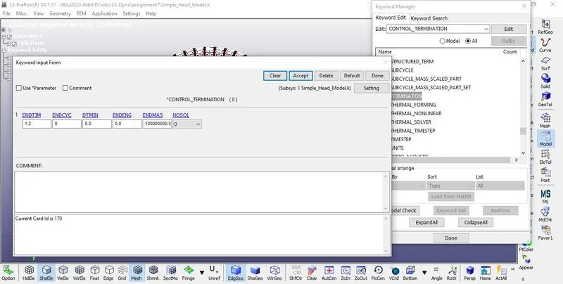
1. Control card *CONTROL_TERMINATION is specified
2.Termination time defined by using Control_Termination card, The termination time is set to 1.2ms
Database Creation
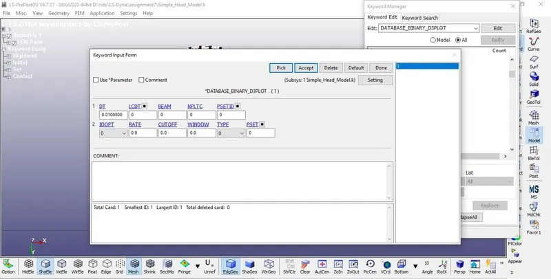
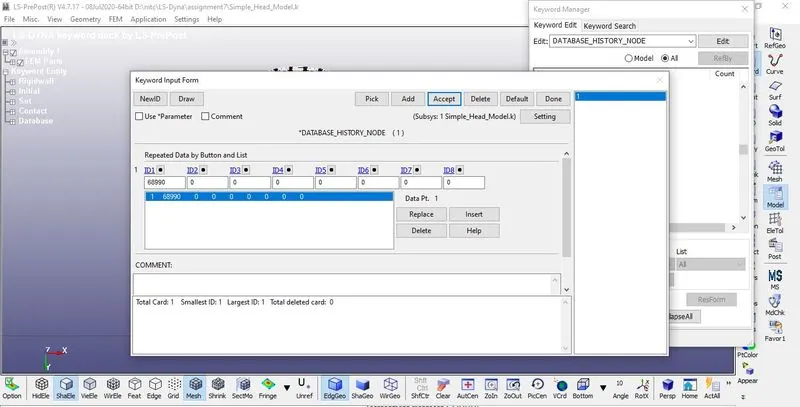
1. BINARY_D3PLOT - It defines the frequency at which the animation file is to be created and is set to 0.01
2. DATABASE_HISTORY_NODE- A set of nodes created Below the Head where It will impact to measure the acceleration And HIC value
OUTPUT REQUEST:-
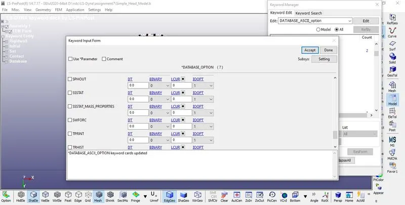
1. To view the results of Simulations Following Steps are Specified.
2.The time interval between the outputs is 0.05 is defined in D3plot
3. Go to Keyword Manager > Database > ASCII select GLSTAT, RCFORC with DT 0.01
4. ELOUT, MATSUM, GLSTAT, RCFORC, RWFORC, SWFORC, NOD OUT this required option assigned into the ASCII option.
Model Checks:
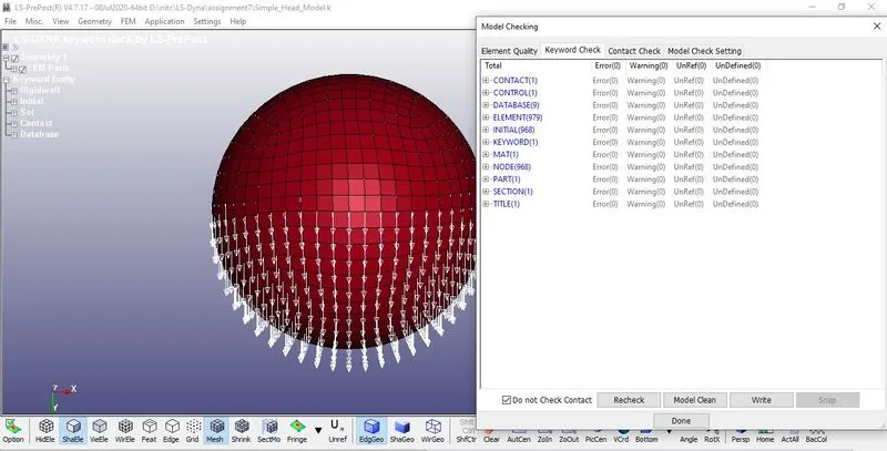
check the model whether any errors were there and correct them.
Figure19 shows the model after correcting the errors.
Run The Simulation.
Save the edited keyword in a separate folder and Run the Simulation in LS Run.
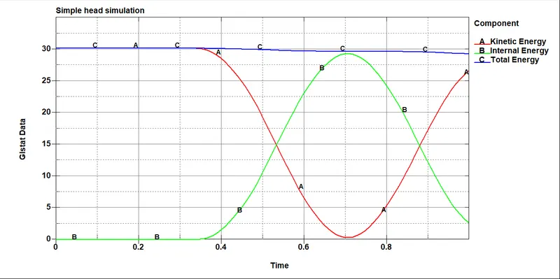
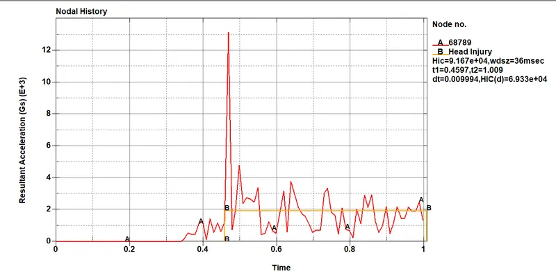
1. In the first case, the Headform is defined with the MAT_ELASTIC material card so that we can see the stress acting on the head only during the Time of Impact and Rebounds to its original shape as soon as after the Impact.
2. The head form only consists of shell elements, as there is No accelerometer Placed to measure the Resultant Acceleration or HIC value.
3. So even the HIC value Could be plotted by taking a node at a point of Impact and Plot the HIC values The value Obtained might Not be realistic in Nature.
CASE-2: HEADFORM IMPACT ON THE RIGID WALL:-
1. As per the Automotive Industry standards AIS 100 The Headform should be Set Up.
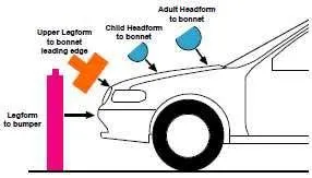
2. The Angle of Impact of the Headform Must be within 35-75 degrees and the Speed of the Impact Should be 40kmph (11.11mm/ms)
3. The Pedestrian Headform is Imported
4. As we can see the pedestrian Head form is in the Angle 90deg with respect to the z-axis considering x and y as base
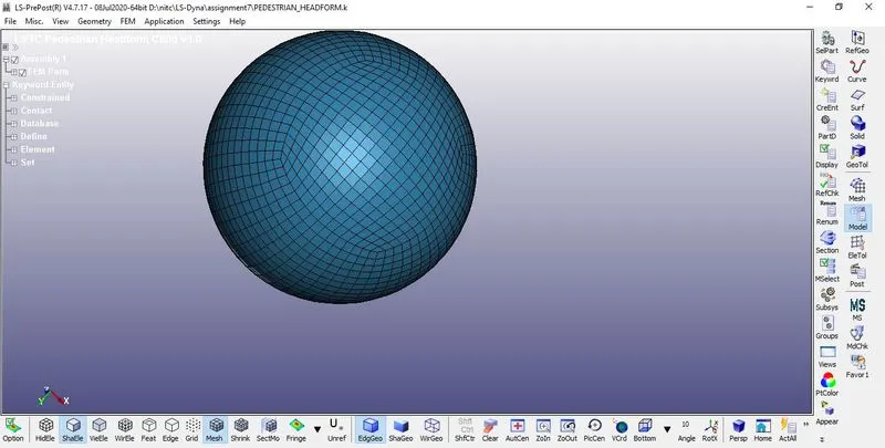
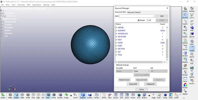
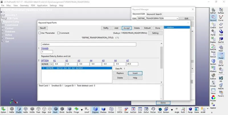
5. Since the Transformation of original Geometry Is necessary To replicate the Solution Like real-time Impact *DEFINE_TRANSFORMATION Card is used.
6. A new keyword file Is created for the Rotation of the Headform Using the *DEFINE_TRANSFORMATION card.
7. Give TRANID as 1 and Choose Rotation as Option
8. The head form is rotated Along Y-axis at an angle of 45deg
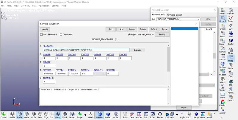
9. *INCLUDE_TRANSFORM card is used to Complete the Rotation Process.
10. While defining *INCLUDE_TRANSFORM card Original Geometry which is Pedestrian head form is called and TRANID is Applied.
11. The Keyword is saved in the same Folder Where the Original Geometry Is Saved.
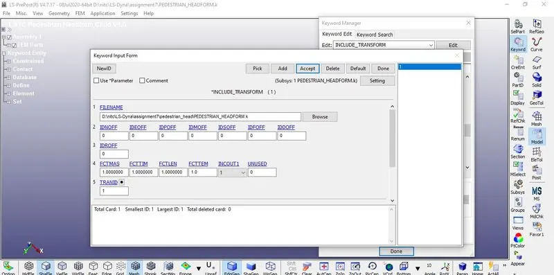
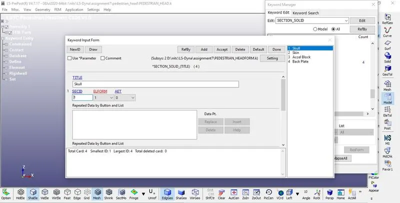
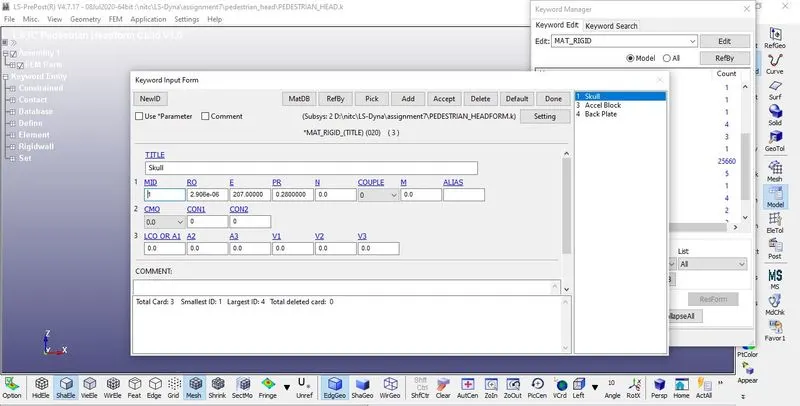
12. Both *INCLUDE_TRANSFORM and *DEFINE_TRANSFORMATION cards are included with the original geometry
13. Import the New keyword which contains Both *INCLUDE_TRANSFORM and *DEFINE_TRANSFORMATION cards
14.As we can see the Headform is Inclined at an angle of 45deg from the Global Axis
Rigid wall creation:-
1. A Rigid wall is created Normal to the Z-axis by Create entity >Rigid wall > Planar option like same as the previous process
2. The Rigid wall is Displaced 15mm normal to the Z-axis
Section Creation:-
1.Here The *SECTION_SOLID is predefined for all the parts in the Headform with Element Formulation 1
MATERIAL:-
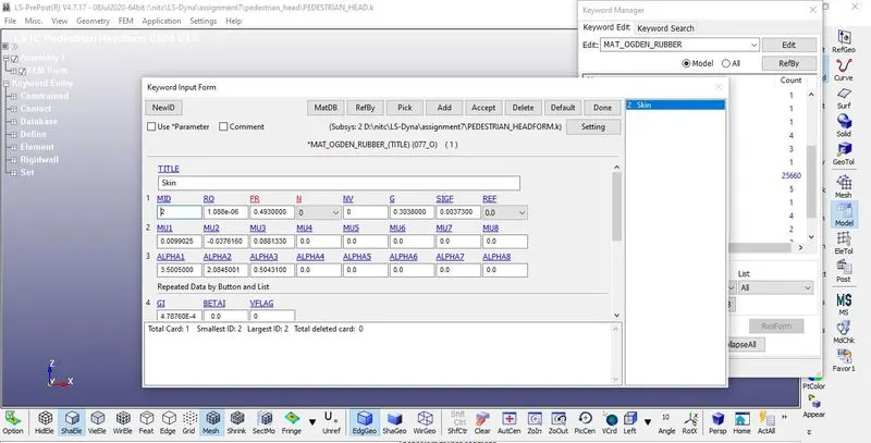
The material is predefined in the Keyword, for Skull, Accel block, plate MAT_020_Rigid IS defined and for the Skin, MAT_O_077_Odgen rubber is Used
The accelerometer was Placed Inside the Inner sphere, which is used to record the Impact
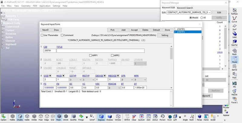
Contact Automatic Surface To surface Is predefined with Skull as master and Skin as Slave.
Other predefined Cards Such as:-
Constrained: Extra_nodes_Set, Rigid_bodies
Control: Bulk_viscosity, Time_step, Energy, Output..
are Noted for their parameters.
Boundary condition:-
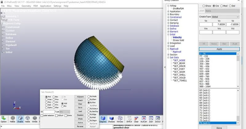
As the velocity of impact is 11.11mm/ms is defined in the previous case as its is acting in a single direction before rotation is Induced
Since the Model is rotated to a certain angle the velocity should be resolved according to the axis
In this case, The Headform is rotated 45 deg
Vx =-7.85
V= -7.85
Control Cards:
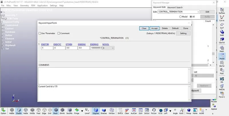
Control_Termination is defined at what time the simulation ends or the end time of the simulation. It is set to 5ms
OUTPUT REQUEST:-
1. To view the results of Simulations Following Steps are Specified.
2.The time interval between the outputs is 0.05 is defined in D3plot
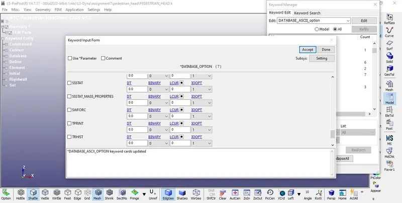
3. Go to Keyword Manager > Database > ASCII select GLSTAT, RCFORC with DT 0.1
4. ELOUT, MATSUM, GLSTAT, RCFORC, RWFORC, SWFORC, NOD OUT this required option assigned into the ASCII option.
RESULTS
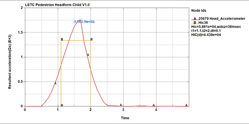
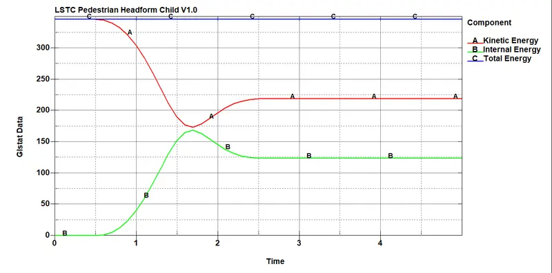
1. In case -2 the Head is Set up as per AIS100 regulations and Impacted On the Same Rigid wall again. The Child Headform is Assigned with Proper Materials, and an accelerometer Is placed for recording the Impact.
2. Since the HEadform is Impacting the rigid wall Which is Undeformable, we can see a Drastic amount of Stress acting on the head and it is failed to rebound to its original shape
3. The Hic value obtained here is Less than the Case-1, It IS because Of the change in MAT Cards related to the real-life experiment in case-2, As the Rigid wall is the same in Both cases.
4. Since Hyperelastic Material Is used It absorbs More More stress and Strain, So the HIC value is Comparatively Less with Case-1
CASE-3: IMPACT Of HEADFORM in THE HOOD:-
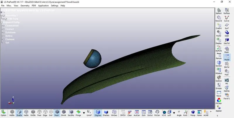
1. The Meshed Hood is Imported As per the Automotive Industry standards AIS 100, in a new keyword File
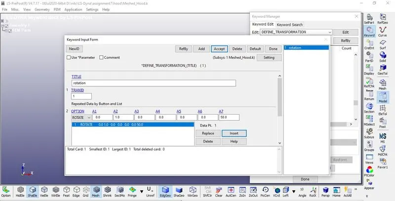
2. The head form is rotated about 50deg release angle using *DEFINE_TRANSFORMATION card So like the previous case
3. The HeadForm Model is called Using *INCLUDE_TRANSFORM to the Hood Keyword file
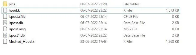
4. The Keyword is saved in the same Folder With the Hood
Section Creation:-
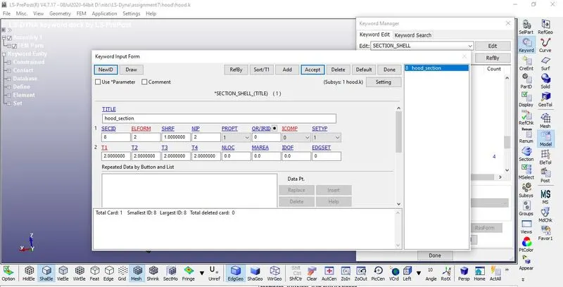
1. The sections of the Headform is predefined, so the sections of Hood are Created
2. For the Hood, Section Shell is Assigned, as it has meshed with The 2D element
3. SECTION_SHELL card with ELFORM-2 And Thickness of 2 is Assigned
Material:-
1. Since the Impact on the rigid wall is replaced By a Hood, proper Material should be assigned for the Hood Too.
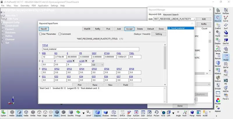
2. In this case, The Hood is assigned with the Material card *MAT_024 or *MAT_PIECEWISE_LINEAR_PLASTICITY, With the Properties of Aluminium.
3. MAT_24 is an elastoplastic material card since the Hood has chances of regaining its shape to its original form after impact and at the same time Hood maybe Deformable if the load is High.
Contact Creation:-
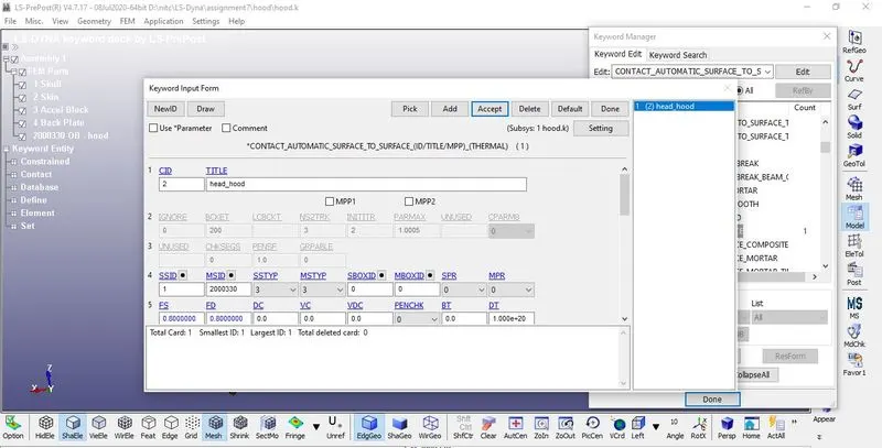
An AUTOMATIC_SURFACE_TO_SURFACE contact has been defined between Hood and headfoamHood as master and the Headform as slave.
Boundary Condition:-
Initial velocity
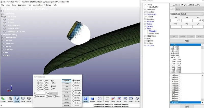
1. The velocity of -7.5mm/ms Is applied normal to the Z-axis and X-axis for looking at exact Impact.
2. As the velocity of impact is 11.11mm/ms is defined in the previous case as its is acting in a single direction before rotation is Induced
3. Since the Model is rotated to a certain angle the velocity should be resolved according to the axis
4. In this case, The Headform is rotated 50 deg
Vx=11.11cos50
Vz=11.11sin50
The resolved velocity is 7.5mm/ms since its acting in a negative direction -7.50mm/ms is defined
Boundary-SPC:-
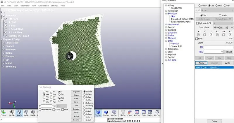
The Corner nodes in the Hood are Constrained in All degrees of Freedom using the Boundary SPC option.
Control Cards:-
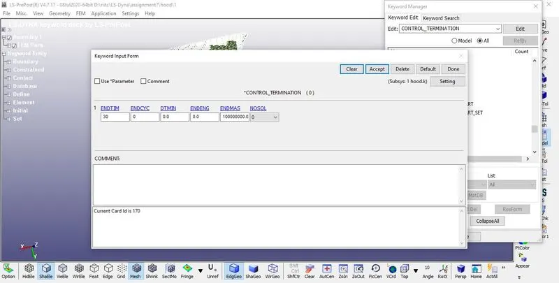
Control_Termination is defined at what time the simulation ends or the end time of the simulation. It is set to 30ms
OUTPUT REQUEST:-
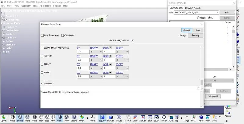
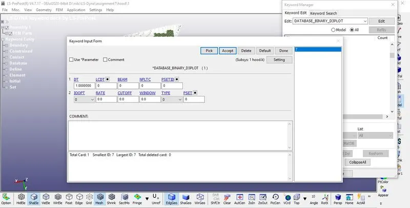
1. To view the results of Simulations Following Steps are Specified.
2.The time interval between the outputs is 1 is defined in D3plot
3. Go to Keyword Manager > Database > ASCII select GLSTAT, RCFORC with DT 1
4. ELOUT, MATSUM, GLSTAT, RCFORC, RWFORC, SWFORC, NOD OUT this required option assigned into the ASCII option
RESULTS:
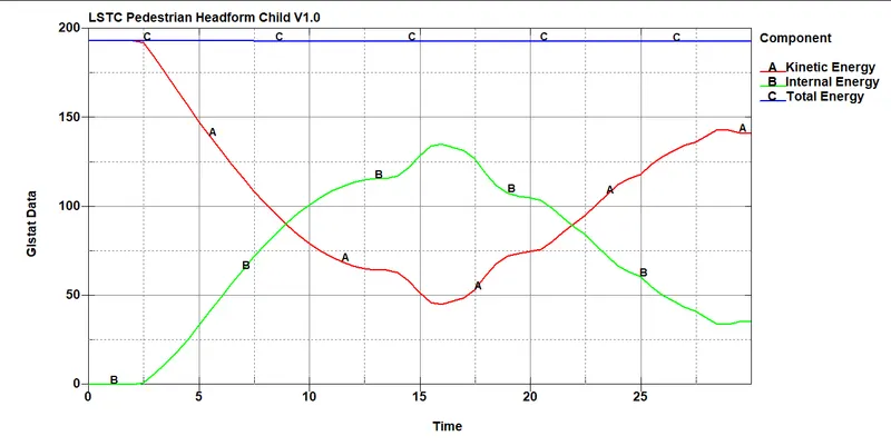
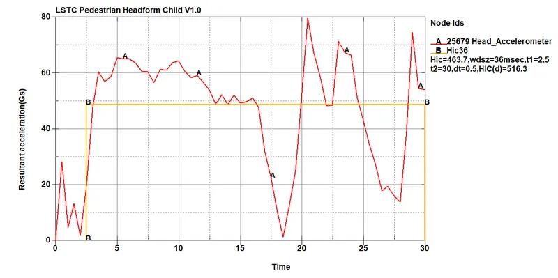
1.In case 3 The Head Model Is set up the same as Case 2 But with The Hood Instead of the rigid wall.
2.The Hood is Assigned with the Material card MAT_024 or MAT_PEICEWISE_LINEAR PLASTICITY To Study the Real-life Impact6 experiment
3. The Hood Is Considerably deformable during the Impact, So the hood deforms significantly While the head from impacting and Absorbs Relative stress and strain more comparatively with the Rigid wall.
4.As The Headform is Hyperelastic with the deformable Hood the HIC value is less Compared with Case-2
Conclusion:-
Thus the HIC value of the pedestrian Head is Solved by the Standard methods, the Value might be differ based on the Material of the Hood, different angles, and Different release angles
The Severity Index for The Head is 2.5 And has different values for different parts Of the Body, HIC value Can be calculated for different parts of the body and COmpared with the standard values.