Assignment 2-RADIOSS Engine File Editing & 3D Meshing Challenge
1) Check the material properties of the rail component and calculate the speed of sound in steel rail=_______
Ans: speed of sound c=`sqrt(E/rho)`
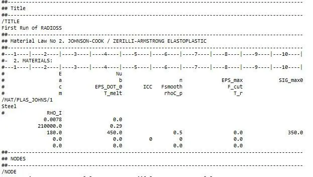
figure1
from the above figure 1 the value of E= 210000 N/mm^2
and rho= 0.0078 g/mm^3
by substituting the values speed of sound c= 5188.745217 m/s
2)The length of the rail is about 1000 mm.calculate the time takes for a shock wave to travel from one end of the rail to the other.
Ans: Time takes for a shock wave to travel from one end of the rail to the other is given as T= l/c
where l = length
T= 1000 mm/(5188.745217 m/s)
T= 0.00019272482 s
T= 0.19272482 ms
3) Time for sound to travel length of rail=______
Ans: To calculate the time firsr we have to calculate length of rail in which the sound wave is travelled by imorting given Radioss file in Hypermesh and calculate lenth of rail by using Nodes as shown in figure 2,3,4 and 5.
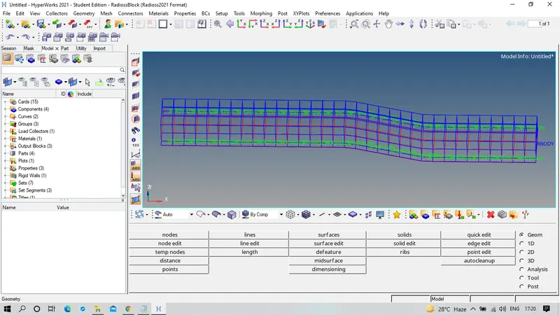 Figure 2
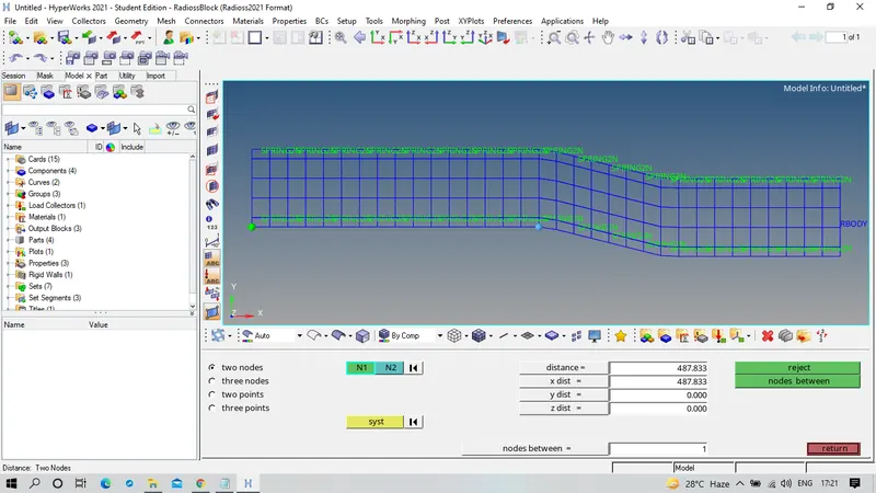 Figure 3
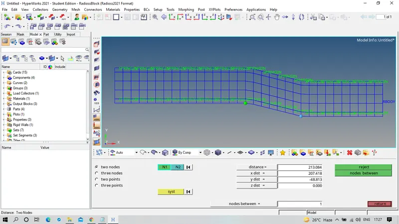 Figure 4
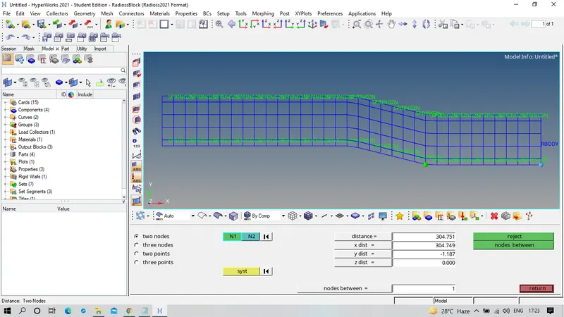 Figure 5
Total length of Rail= 487.833+213.084+304.751
l= 1005.668 mm
time T= l/c = (1005.668 mm)/(5188.745217 m/s)
T= 0.19381719 ms
4) Edit the engine file so that the stress wave can be monitored, moving from one end of the rail to the other during impact -this will require a termination time equal to the time it takes for the sound to travel the length of the rail(set on/RUN card)
Ans: Figure 6 shows edited value of time step
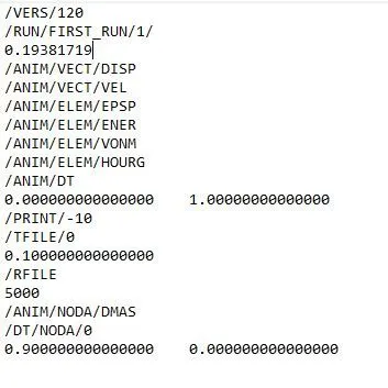
Figure 6
5) Set the frequency of animation output to a time that will give 20 animation steps(/ANIM/DT)
Ans: Figure 7 shows edited value of frequency animation steps
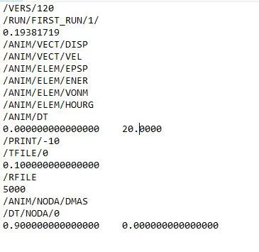
Figure 7
6) Change /print -10.
Ans: Figure 8 shows the edited value
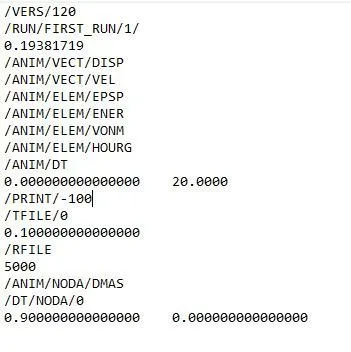
Figure 8
7) 3d meshing tetra mesh and hex mesh
- Repeat class examples and, maintain the quality.
- Target tet size=5mm,hex size=10mm,tet collapse=0.15
Ans:
OBJECTIVE : To perform the 3d meshing Tetramesh and Hexamesh for class examples by maintaining the Quality and Target tet size=5mm,hex size=10mm,tet collapse=0.15
PROCEDURE :
1.Hex 3d mesh on Arm Bracket
To import .stp file click on import option as import as geometry and select STEP file, browse for the required file and import the required file. Figure 9 shows the imported file of Arm Bracket.
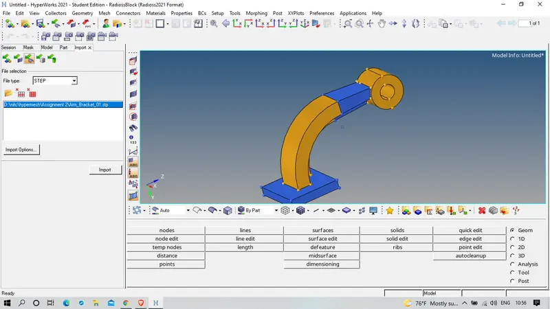 Figure 9
There are five individual parts in the component, First focussing on the Base and hide the other parts, select the top surface of the base and 2d Mesh on that face by choosing Element size 10mm and selecting only Quad elements and complete the 2d Mesh on the surface.Check the quality of the mesh and if certain doesn't qualify for mesh quality then edit that elements to get Good Mesh quality. Figure 10 shows 2d Mesh on the top surface.
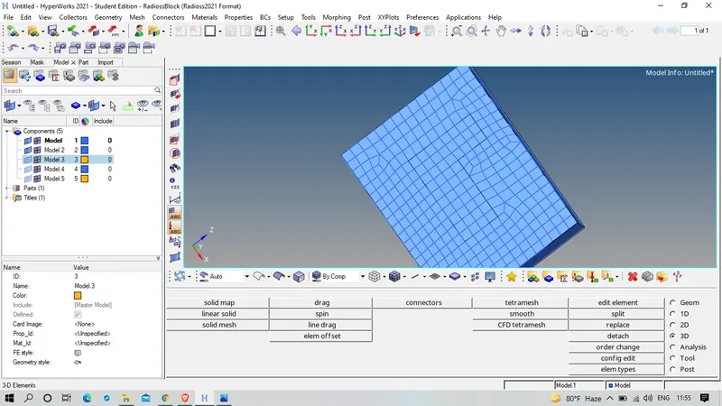 Figure 10
After that enter into 3d panel inthat click on element offset inthis select solid layers, select the 2d elementa to offset after that select the surfaces along with the geometry to follow and set no of layers to 5 and calculate the thickness value and after that click on offset+ or offset- according to the mesh create dimension. Figure 11 shows selection of surfaces for which 2d mesh geoetry should follow. Figure 12 shows finalized 3d mesh model of base.
Figure 11
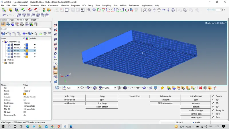
Figure 12
Now unhide the 3rd part as shown in figure 13, and we have to make sure that everytime we select other part make that part as a current and hide 3d elements of first part by maskin where the elements were selected by config where select hex8 and mask all 3d elments, since the selected part is curved select spin in 3D Panel, spin elements in which angle 90 degrees and bias density 25, select 2d elements that to be spin and before that we have to get the circle centre and it can be know by selecting distance in geometry panel or pressing F4 by selecting three nodes on the path and click on circle centre, Figure 14 shows the circle centre finding.
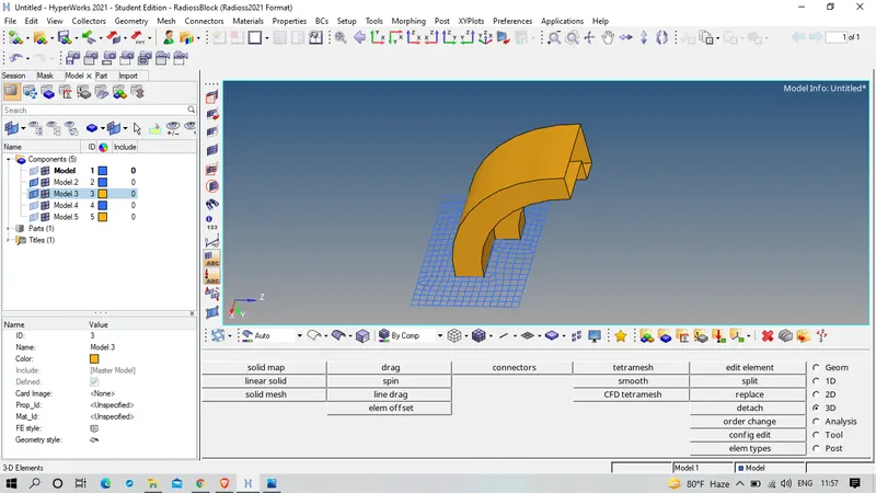 Figure 13
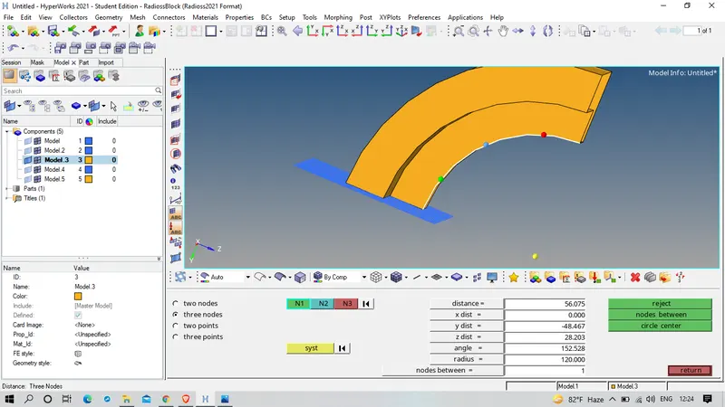 Figure 14
After this selecting perpendicular to the newly 3d meshing elements along which curved path is generating and selecting the circle centre and clickk spin+ or spin- according the dimension of meshing elements.Figure 15 shows the meshed part.
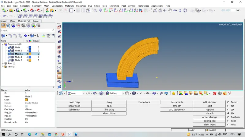 Figure 15
Now unhide the other parts, since this crosssection is decreased on moving select linear solid in 3d Panel in which we have to select from elements to To elements and from initial alignment of elements to final alignment of elements and giving the density and click on solid. During selection of alignment of element care should be taken. Figure 16&17 shows selecting from and to elements and from and to alignment of elements. Figure 18 shows the meshed part.
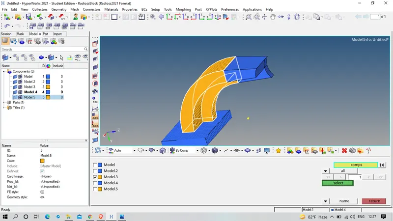 Figure 16
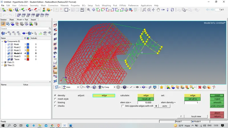 Figure 17
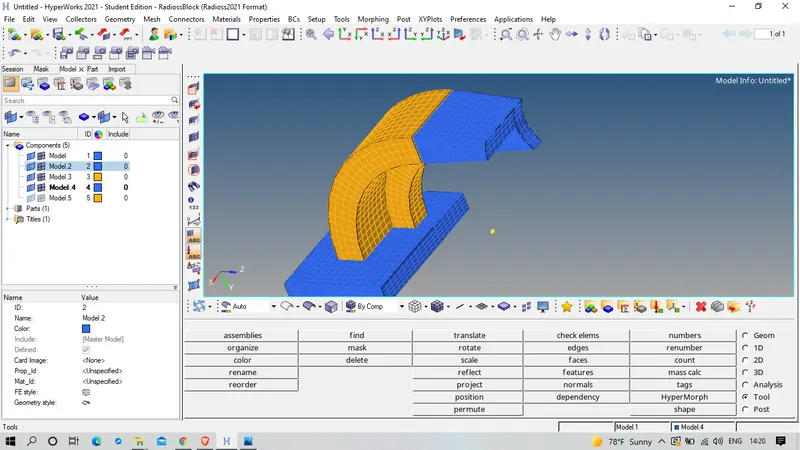 Figure 18
Now unhide the last component, completed automesh on one side as shown in figure 19, select solid map in 3D panel in which selected gneral in which choosen source geometry as none , destination geometry is opposite face along geometry as mixed and selecting no of layers to 10 as shown in figure 20,and completed the mesh. Figure 21 shows the FINAL Meshed component.
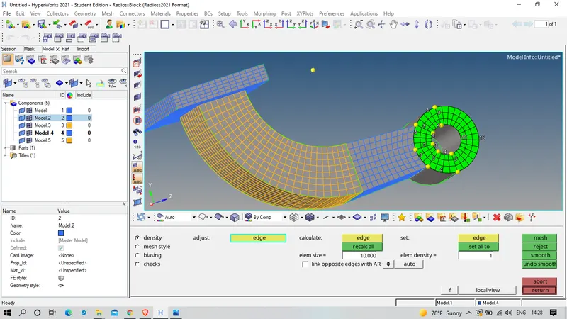 Figure 19
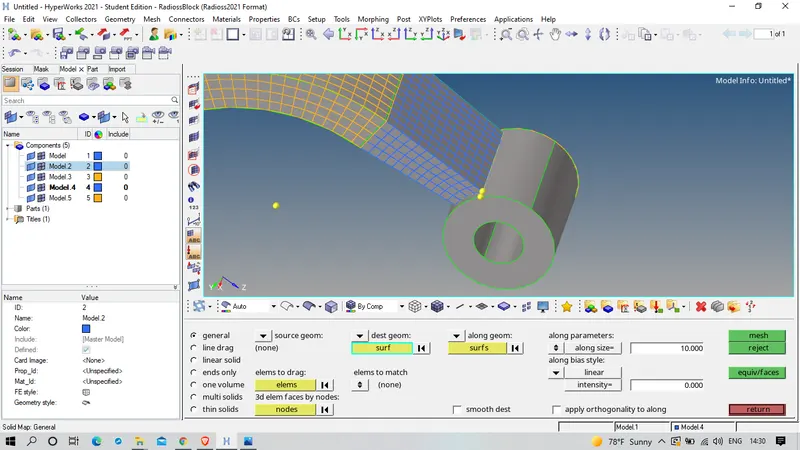 Figure 20
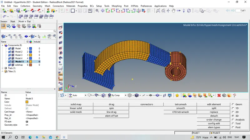 Figure 21
2. Tetra 3d mesh on housing
To import .stp file click on import option as import as geometry and select STEP file, browse for the required file and import the required file. Figure 22 shows the imported file of Housing.
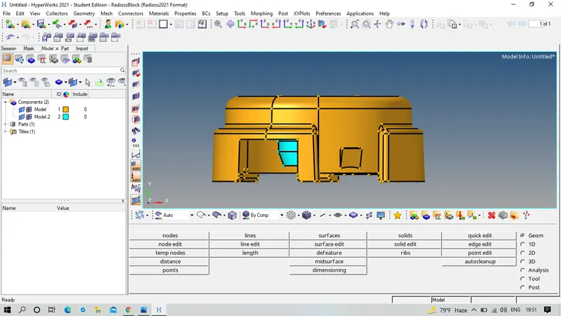 Figure 22
Now Hide the first part after in 3d Panel select Tetramesh in which Tetra mesh subpanel select all the surface that are to be meshed as shown in figure 23 , again in Tetramesh Parameters select minimum tetra size as 3mm and Tet collapse as 0.15 and completed the mesh. Figure 24&25 shows the meshed component.
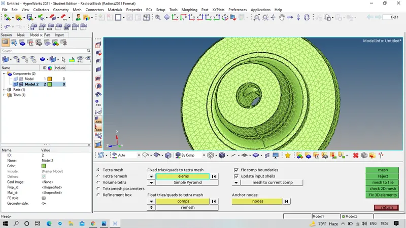 Figure 23
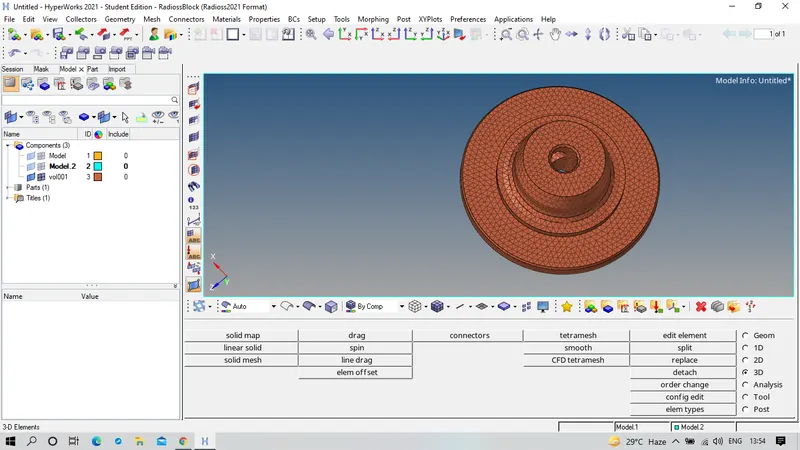
Figure 24
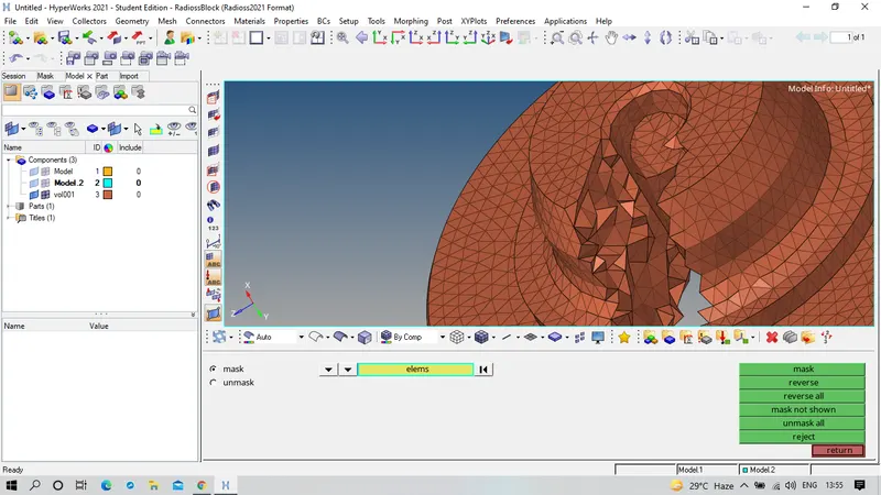
Figure 25
Now unhiding other part and by folowing the process
Components-view-browser-hypermesh-utility-Geom/Mesh- Quick Tetramesh
and here selecting the required component to mesh, size of mesh as 5mm, minimum tria angle 20 and others are not changed and create on mesh.
Advantage of this process it will do cleanup process in geometry.
Figure 26&27 shows the meshed component.
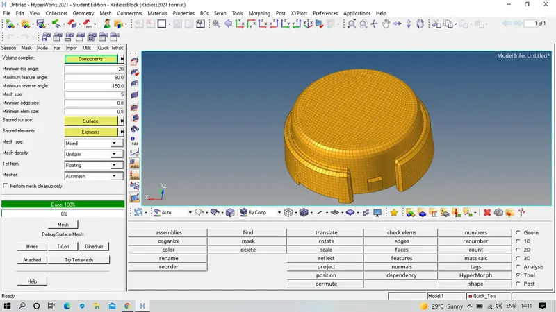 Figure 26
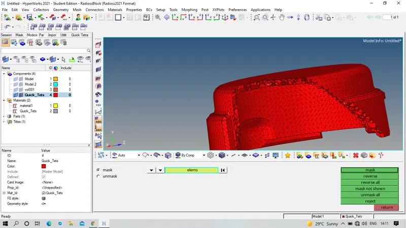 Figure 27
Figure 28 shows the final tetra meshed component
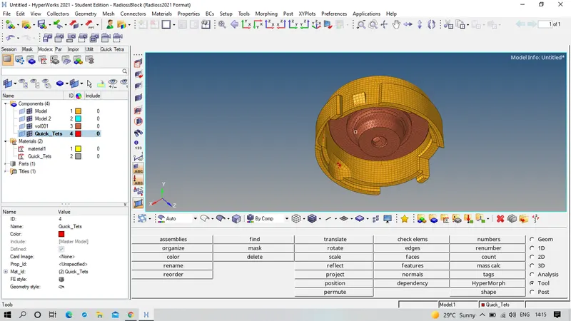 Figure 28
3. 1D_Elements
To import .stp file click on import option as import as geometry and select STEP file, browse for the required file and import the required file. Figure 29 shows the imported file of 1D_Element.
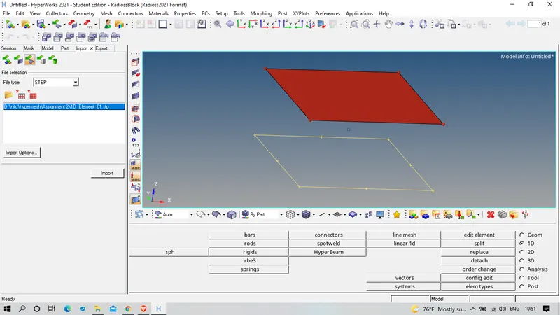 Figure 29
To create surface on other side in geometry section, goto surfaces in which selecting ruled option and created the surface by selecting opposite lines. Figure 30 shows the surface created.
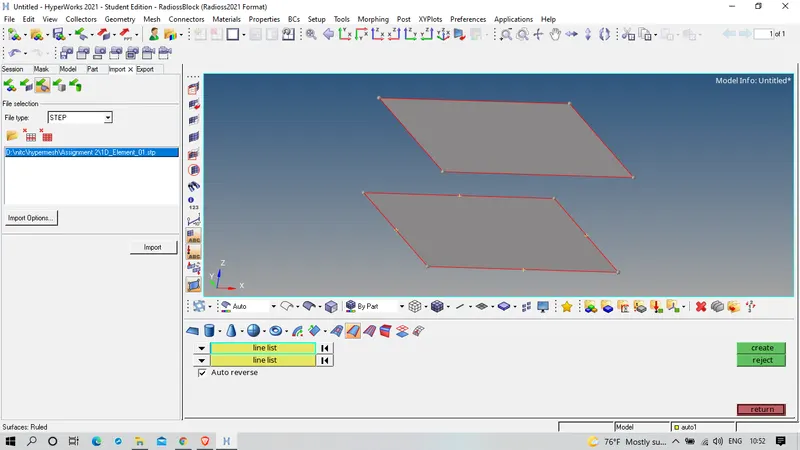 Figure 30
created 2D mesh on both surfaces as shown in figure 31
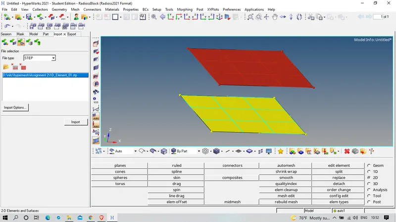 Figure 31
On this created mesh, working on 1D Elements as shown in figure 32.
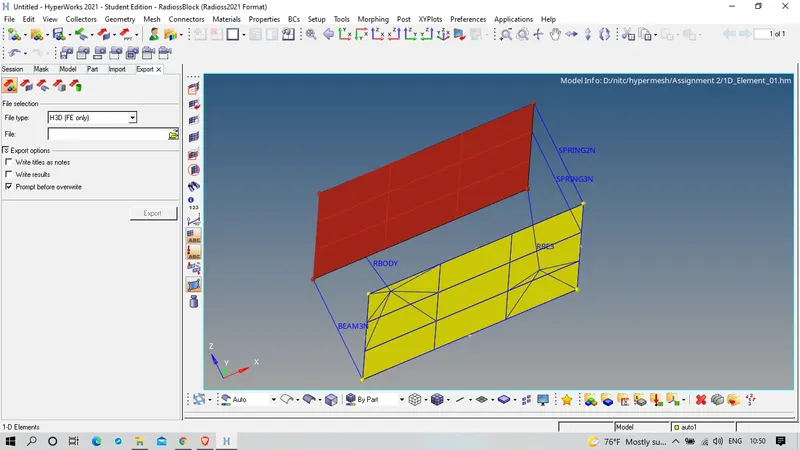 Figure 32
RESULT AND CONCLUSION: Successfully created Hex mesh on Arm Bracket and Tetra Mesh on Housing and worked on 1D Elements. Beginning faced some issuess and finally corrected it.