Assignment 5-RADIOSS Interfaces & Study of Effect of Notches Challenge
Objective:
- Create the mesh for bumper assembly, mesh size should be 6mm.
- Run the crash tube model as it is.
- Change the Inacti=6 and run.
- Create the type 11 contact and run.
- Remove both notches and remove boundary condition on rigid body node then run.
- Create a new notch in the middle, select the whole session and run.
- Create a new notch with nodes only from opposing 2 faces and run.
Bumper Meshing :
Procedure:
First import the Bumper_System.hm model by following > Import > model > select .hm file and import.
After importing the model it will be in Wireframe geometry as shown in figure1, changing that to the solidframe geometry as shown in figure2.
Edit the geometrical and topological defects in the model for better flow of mesh.
In Topo geometry color mode few free edges are found, these free edges can be easily removed by using Surface edit tool available in geometry.
Use quick edit tool in geometry to remove unwanted nodes or Temporary nodes and edges or to project points on to the adjacent lines.
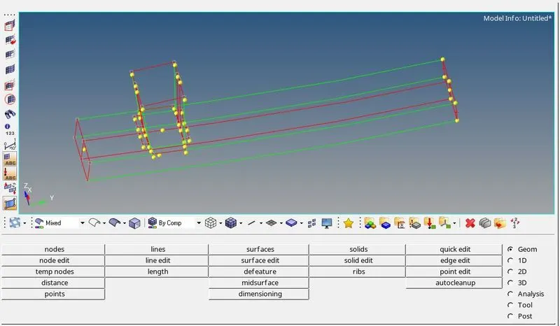
Figure 1
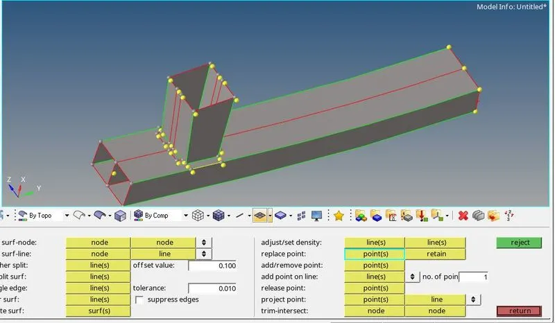
Figure 2
To mesh the model in 2D panel and select automesh, where select element size = 6, and mesh type = quads and make sure that no tria elements were generated during the meshing.
Figure3 shows the final meshing model og the Bumper_System.
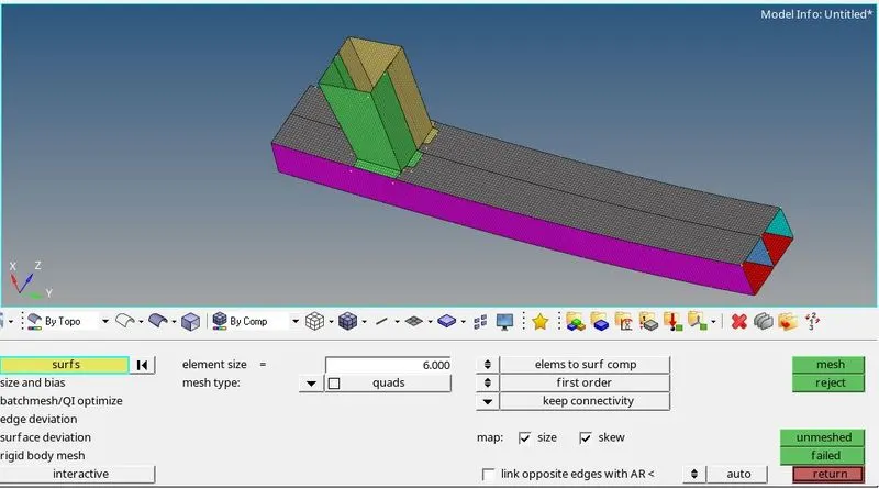
Figure 3
Now we will connect the components having gaps between them with connectors. To connect the components goto connectors panel in 2D page and selected the spot weld connectors to connect the components. Here we will specigy the node location where we want the spot weld, selecting the connecting components and then click on create to create the connectors and connect all the components as shown in the Figure4,5 and 6.
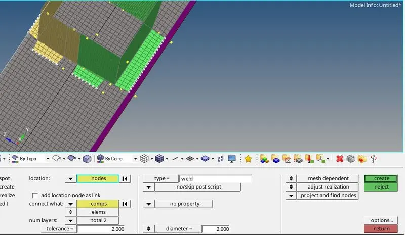
Figure 4
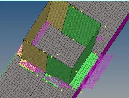
Figure 5
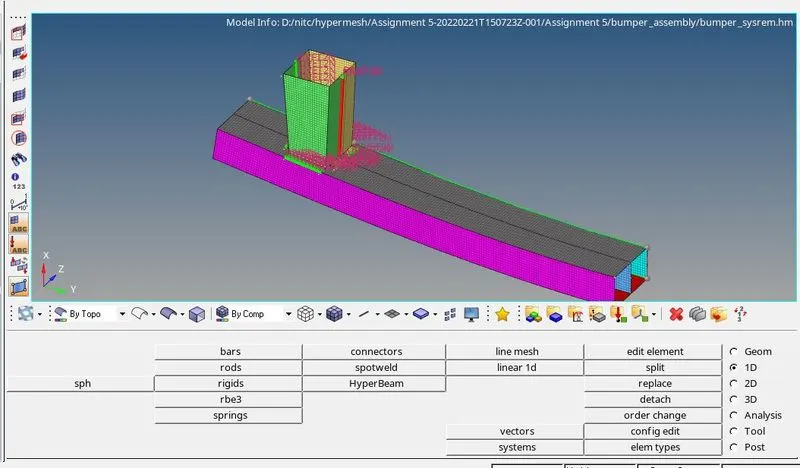
Figure 6
CrashTube Analysis:
Case Description and Procedure:
CASE1: Run the Crush Tube model as it is.
First Import the import Crush_tube_0000.rad starter file using Import Solver Deck menu, as shown in figure7.
Figure8 shows the imported Crush_tube file.
To run the model as it is Navigate to Radioss option in Analysis Panel, in which save the model where we wanted to save the model in a specific folder, and select the include parameters option and under options folder write -nt 4 ( to run 4 cpus at a same time) and click on Radioss to run the simulation.
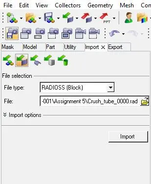 Figure7
 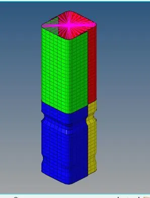 Figure8
After completing of simulation open the .out file in Notepad to know the Energy error, mass error and elapsed time as shown in Figure9
1) Energy error = -3.8%
2) Mass error = 0.000
3) Starter runtime = 14.35s
4) Engine runtime = 303.91s
5) Total number of cycles = 83529
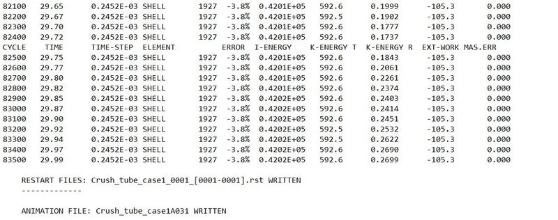
Figure 9
To run the Animation files, Switch to Hyperworks View and in Hyperworks view import the .h3d file as shown i Figure10.
In this model, initial bending or failure occures at the upper notch and then bending or failure occures at the lower notch, due to this Upper part deformation is starts after only the complete deformation of lower part of the tube.
Animated video file for Von Mises failure are uploaded as case1.mkv
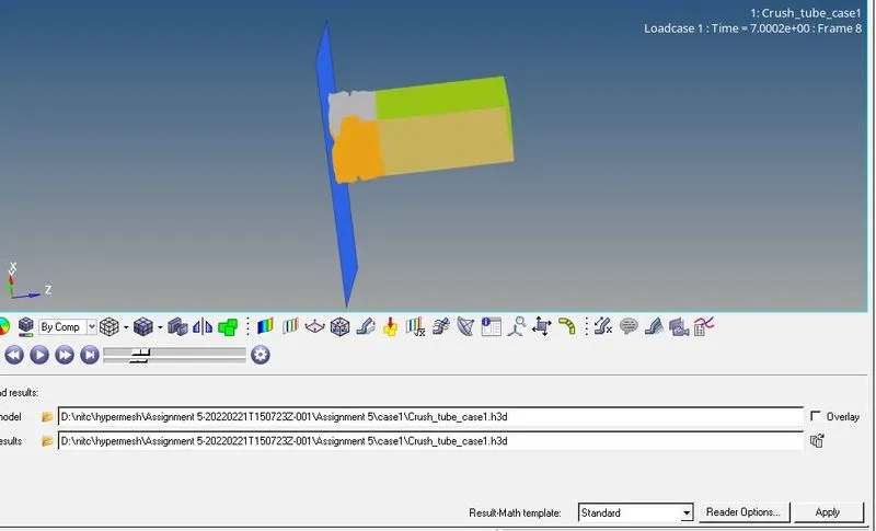
Figure10
To plot the resuts, switch to HyperGraph 2D and import the T01 files and then plot the results as shown in Figure11 and 12.
Rwall Forces - From the plot we can see that the effect of Normal force at intial stage is less due to the opposing resistance of the crash tube and increases when the crash tube is deforming and again decreases to zero after complete deformation of crash tube.
Contact, Internal, Kinetic and Total Energy - Contact energy increases with time as the model deforming in zigzag way and the material accumulation layer by layer which incrases the contact forces. Kinetic energy having higher value at the start of the simulation decreases as the simulation progresses with time and these energy is converted into the Internal energy of the system due to this internal increases with time and overall total energy almost constant.
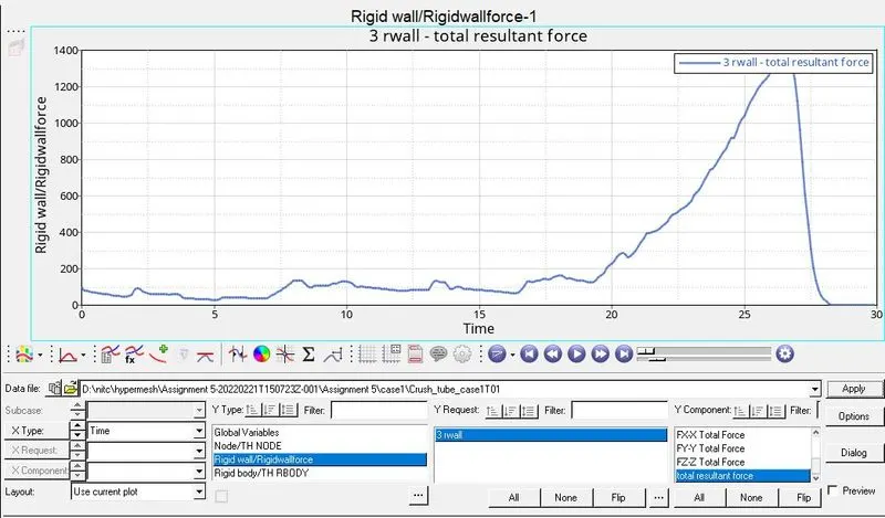
Figure11
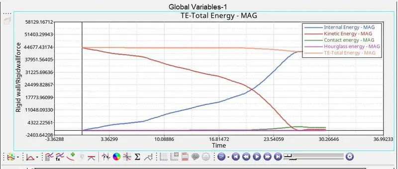
Figure 12
CASE2: Change the Inacti=6 and run.
Import the starter .rad file, Open Solver browser in which open groups and click on self contact and edit the Inacti value of TYPE7 contact to 6 (i,e Inacti=6) as shown in figure 13 and 14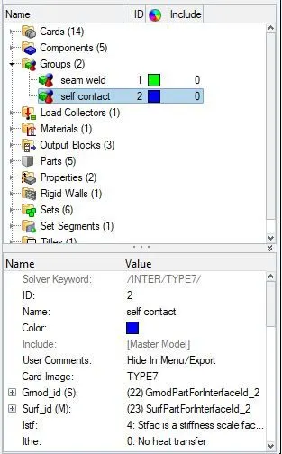 figure 13
 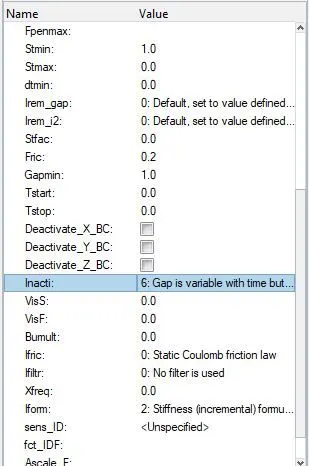 figure 14
To run the model Navigate to Radioss option in Analysis Panel, in which save the model where we wanted to save the model in a specific folder, and select the include parameters option and under options folder write -nt 4 ( to run 4 cpus at a same time) and click on Radioss to run the simulation.
After simulation is completed open .out file to know about the energy error, mass error and number of cycles etc.
To run the Animation files, Switch to Hyperworks View and in Hyperworks view import the .h3d file
Animated video file for von mises failure is uploaded as case2.mkv
To plot the resuts, switch to HyperGraph 2D and import the T01 files and then plot the results as shown in Figure15 and 16.
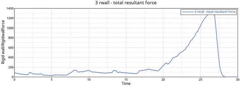
Figure 15
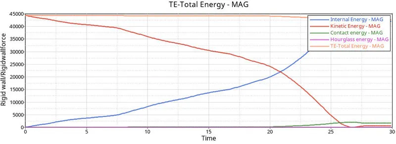
Figure 16
There is no much changes in the rigid wall force and change in energy values compared to previous values.
CASE3: Create the new type 11 contact and run the model.
For this case we will use HyperCrash to create new interface type easily. HyperCrash is a specialized preprocessor for Radioss.
Import the file by drag and drop from its location to the workspace of hypermesh.
In menu bar, navigate to Loadcase > Contact Interface > Create new > Edge to Edge (Type11) contact and configure the recommended parameters as shown in figure17 and 18.
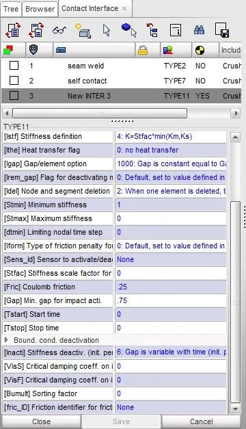
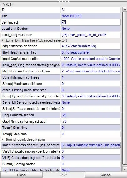
Figure17, Before creating Type 11 contact Figure18, After creating Type 11 contact
As the model is self-contacting, we will check Self Impact option which implies that the components selected for master will also selected as slave because the edge to edge contact happens when impacting line can belong to the the master and the slave side hence for master line option we will select all the 4 components of the model. Export the model and save it in specified path. Import that specific model and run the simulation by Navigating to Radioss Panel in Analysis page.
To run the model Navigate to Radioss option in Analysis Panel, in which save the model where we wanted to save the model in a specific folder, and select the include parameters option and under options folder write -nt 4 ( to run 4 cpus at a same time) and click on Radioss to run the simulation.
After simulation is completed open .out file to know about the energy error, mass error and number of cycles etc.
To run the Animation files, Switch to Hyperworks View and in Hyperworks view import the .h3d file
Animated video file for deformation and von mises failure is uploaded as case3_1.mkv and case3_2.mkv
To plot the resuts, switch to HyperGraph 2D and import the T01 files and then plot the results as shown in Figure19 and 20.
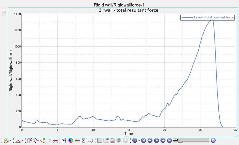
Figure19
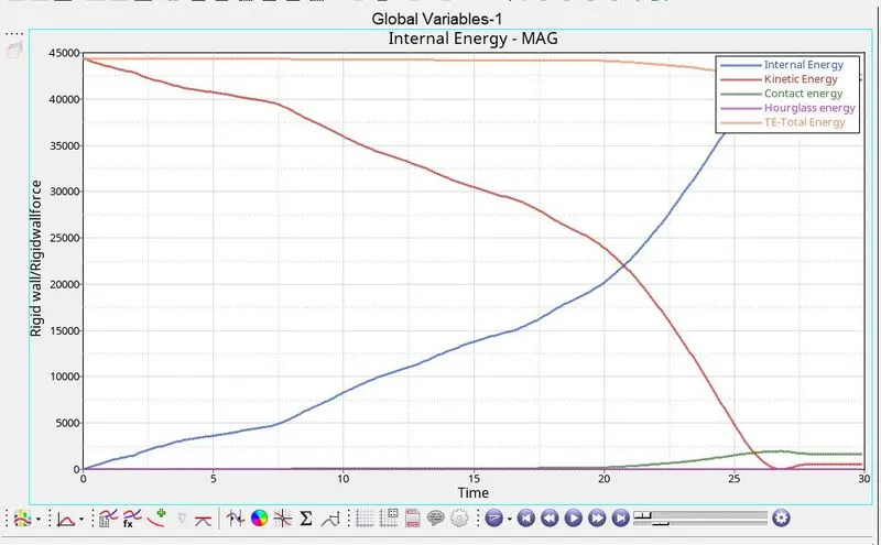
Figure20
CASE4: Remove both the notches and remove boundary condition on rigid body node then run the model.
Import the starter file in Hypermesh and delete the boundary condition from BCS card solver as shown in figure21 and 22, then remove the notches by using Align Node option in Node edit as shown in figure 23. Figure 24 shows the final model with removing all the notches.
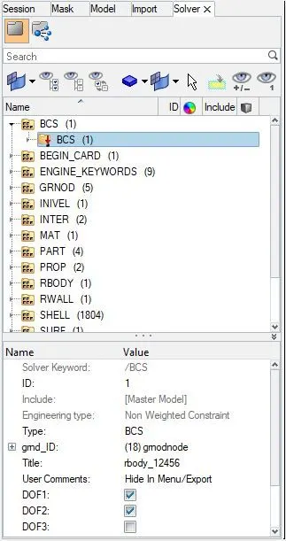
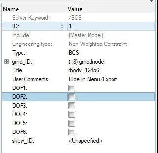
Figure21, before deleting of Boundary Condition Figure22, After deleting of Boundary Condition
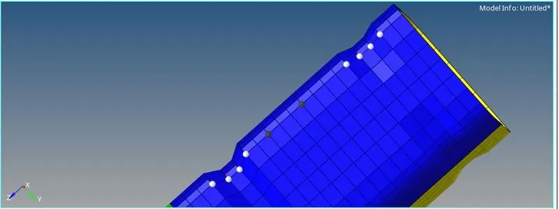
Figure23
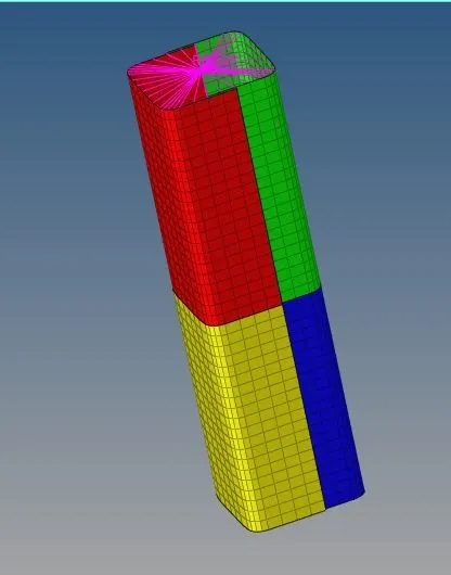
Figure24
To run the model Navigate to Radioss option in Analysis Panel, in which save the model where we wanted to save the model in a specific folder, and select the include parameters option and under options folder write -nt 4 ( to run 4 cpus at a same time) and click on Radioss to run the simulation.
After simulation is completed open .out file to know about the energy error, mass error and number of cycles etc.
To run the Animation files, Switch to Hyperworks View and in Hyperworks view import the .h3d file
Animated video file for deformation and von mises failure is uploaded as case4_1.mkv and case4_2.mkv
To plot the resuts, switch to HyperGraph 2D and import the T01 files and then plot the results as shown in Figure25 and 26.
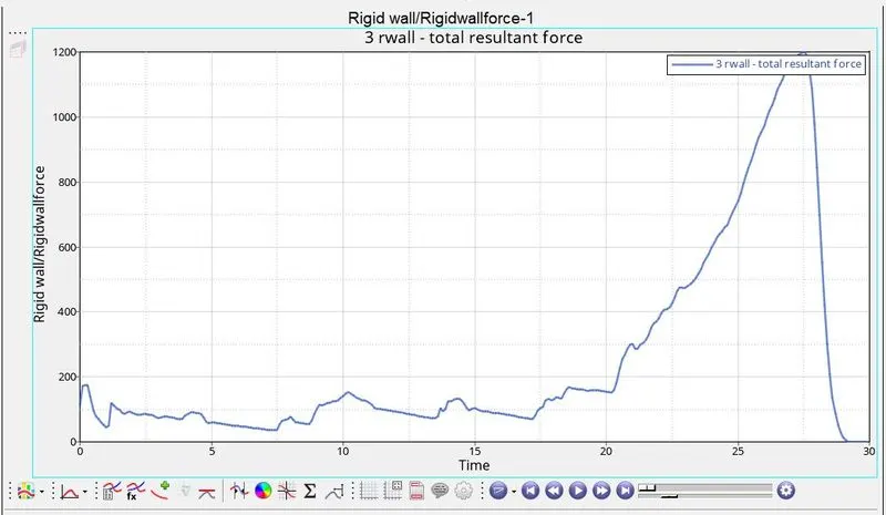
Figure25
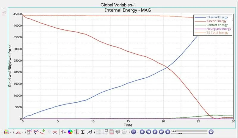
Figure26
In this case due to removing of notches plane uniform surface throughout the component, hence there is no geometrical irregularity or discontinuity the force that applied on upper edge is directly to the bottom edge and deformation starts from bottom in zigzag manner
RWALL FORCES: In this case the Normal and Total resultant forces are comparatively less than the above mentioned cases as the boundary condition is removed.
CONTACT, INTERNAL, KINETIC AND TOTAL ENERGY: Contact energy is decreased due to removal of notches and slight amount of kinetic energy is decreased and subsequent amount of internal energy is increased and total energy remains same.
CASE5: Create a new notch in the middle, select the whole section and run the model.
Import the starter file using Import Solver Deck menu and remove all the notches by following the same procedure in case4 then create a new Notch in the middle portion of the model as shown in below figures.
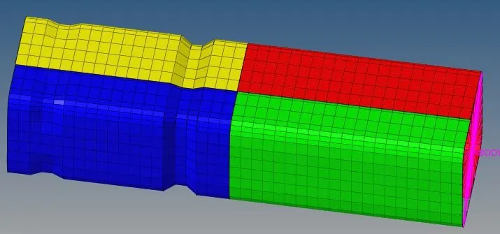
Figure27, Before creating a Notch in the middle
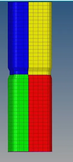 Figure28, After creating a Notch in the middle.
To run the model Navigate to Radioss option in Analysis Panel, in which save the model where we wanted to save the model in a specific folder, and select the include parameters option and under options folder write -nt 4 ( to run 4 cpus at a same time) and click on Radioss to run the simulation.
After simulation is completed open .out file to know about the energy error, mass error and number of cycles etc.
To run the Animation files, Switch to Hyperworks View and in Hyperworks view import the .h3d file
Animated video file for deformation and von mises failure is uploaded as case5_1.mkv and case5_2.mkv
To plot the resuts, switch to HyperGraph 2D and import the T01 files and then plot the results as shown in Figure29 and 30.
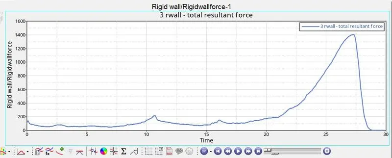
Figure29
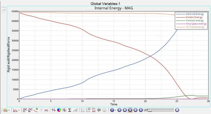
Figure30
In this case the deformation is seen initially at the notch position because it causes geometrical irregularity and thus thus the stress formation is higher in that area, lower part is first deformed then the upper part deforms completely.
Due to change in Notch location, The Normal and Total resulatant forces are higher than than that of previous cases, contact energy is also higher compared to previous cases and there are slight changes in the profile of internal, kinetic and total energy.
CASE6: Create a new notch with nodes only from opposing 2 faces and run the model.
Import the starter file using Import Solver Deck menu and remove all the notches by following the same procedure in case4 then create a new Notch in the middle portion of the model, then by using align node from Node edit Option remove the notches in adjacent side as shown in figures.
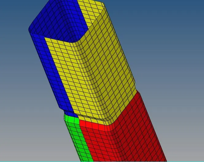
Figure31, Before deleting the adjacent notches
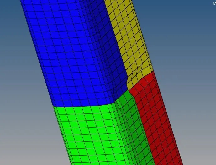
Figure32, After deleting the adjacent notches.
To run the model Navigate to Radioss option in Analysis Panel, in which save the model where we wanted to save the model in a specific folder, and select the include parameters option and under options folder write -nt 4 ( to run 4 cpus at a same time) and click on Radioss to run the simulation.
After simulation is completed open .out file to know about the energy error, mass error and number of cycles etc.
To run the Animation files, Switch to Hyperworks View and in Hyperworks view import the .h3d file
Animated video file for deformation and von mises failure is uploaded as case5_1.mkv and case5_2.mkv
To plot the resuts, switch to HyperGraph 2D and import the T01 files and then plot the results as shown in Figure33 and 34.
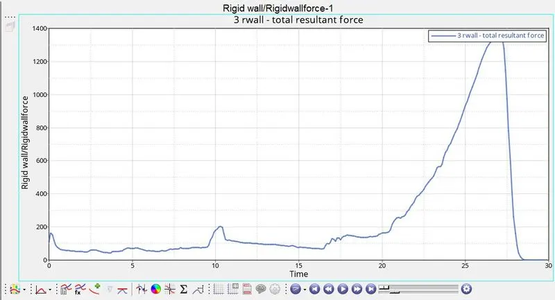
Figure33
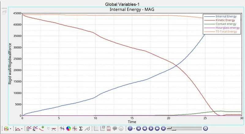
Figure34
In this case, the initial deformation happens at the location of the notch. The two opposite notched faces deforms inwards and the faces adjacent to them deform outwards which again follows up with zigzag layer by layer formation.
There is only slight changes by comparing with case5 in Rigidwall forces, Contact, Internal, Kinetic and Total Energy.
RESULTS:
Comparing all the six cases
| Case No. | Total number of cycles | Energy Error | Mass Error | Total simulation Time (in seconds) |
| 1 | 83529 | -3.8% | 0.00 | 318.26 |
| 2 | 83529 | -3.8% | 0.00 | 181.61 |
| 3 | 82174 | -3.8% | 0.00 | 307.92 |
| 4 | 78422 | -3.0% | 0.00 | 320.80 |
| 5 | 104340 | -3.4% | 0.00 | 404.24 |
| 6 | 88690 | -3.7% | 0.00 | 178.13 |
CONCLUSION:
Studied about the different types of contact interfaces namely Type 7 and Type 11 and studied the different caused in the analysis due to notch geometry.