Assignment 3-2D Element Formulation Challenge
OBJECTIVE: Comparison of results with base simulation and improved shell element properties.
CASE1 SETUP AND PROCEDURE:
First import the Element_Formulation-Shell-3_assignment_0000.rad file in Hyperworks. To import this file, Import - Import solver deck - Browse the file - import the file. After importing components are look like in Wireframe element skin only (default) as shown in Figure1 , by clicking shaded elements, Components look like a completely shaded.
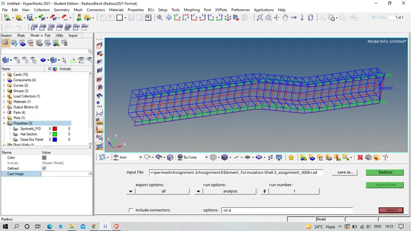 Figure 1
To change Run time to 55ms, Model Browser-cards-ENG_RUN-Tstop-change to 55ms
Figure 2 shows the changing of Run time
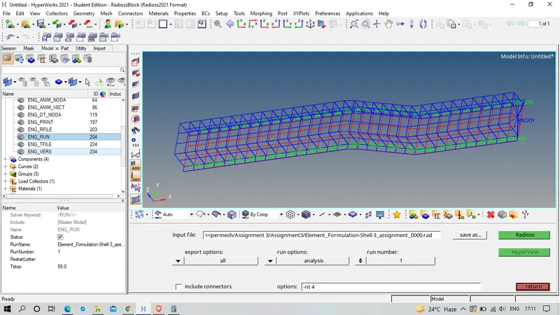 Figure 2
To change the number of animation steps during simulation to a minimum of 25 and maximum of 60, I am selcting 40 animation steps
we know that Tfreq = (Time step)/(no of steps)
Tfreq= 55/40
Tfreq = 1.375
Figure 3 shows the changing of Tfreq value to get 40 animation steps.
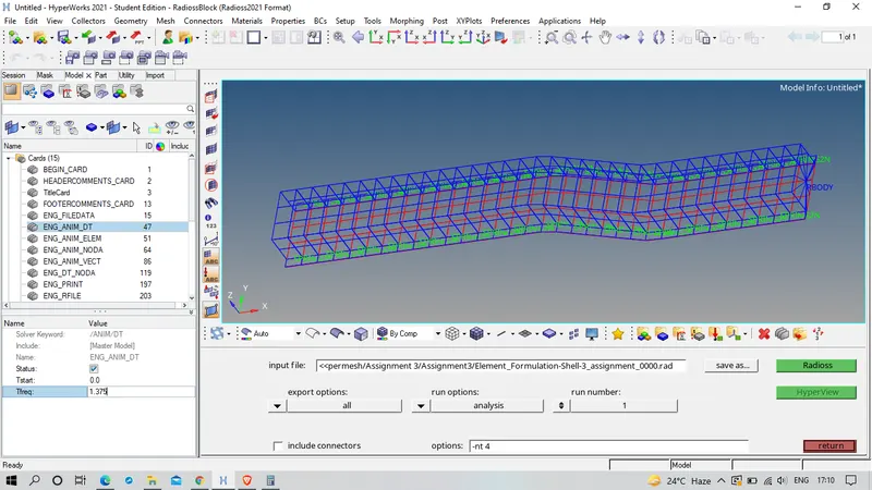 Figure 3
To run the Base simulation, Analysis - Radioss - select where to save file - select all in export options(because if we select displayed and by mistakely if we switched off some components then that components are may not consider for simulation) - in 0ption use -nt 4 for faster simulation ( four cpus run simultaneously) - Hit on Radioss .
To check the Energy error and Mass error checks open the Engine output file (Runname_0001.out) in Notepad as shown in the figure 4.
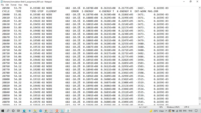 Figure 4
Energy Error:
- The error must be negative and decreasing (except for the first cycles or in spring back stage). The error must be less than 15% at the end of computation ( 5% for a good model ). If the error increases a little, then decreases may be normal. If the error increases, this means that a problem has occured. Then, the error may grow to 99.9% with computation failure message.
- So ideally the error should be at most -15% and better to have -5%. The closer to 0% error the better. For QEPH shell formulation or fully integrated elements, the Energy Error can be slightly positive since there is no Hourglass energy and the computation is much more accurate. An error of 1 or 2% will be acceptable. Otherwise any positive energy error means energy has been created which indicates a model issue.
- If the error is negative, it means that some energy has been dissipated.
In case of under integrated elements (Belytschko shells, solids with 1 integration point), the Hourglass energy can also explain a negative Energy Error since it is not counted in the energy balance. The normal amount of Hourglass energy is about -10% to -15%.
- If the error is positive, there is an energy creation.
In case of using QEPH shell formulation (Ishell=24) or fully integrated elements, the Energy Error can be slightly positive since there is no Hourglass energy and the computation is much more accurate. An error of +1% or +2% is acceptable
If the positive energy error is greater than 2%, the source of this energy has to be identified. Incompatible kinematic conditions can lead to such a situation.
From the above figure 4, The Energy error value is -10.3% and the mass error is constant throughout i,e 0.1659E-03, both the results are in aacceptable level.
To view the Animated file enter into the Hyperview and browse for the .h3d file
The animated results of the analysis are uploaded in video format
video1_before_properties_change.mkv
video2_before_properties_change.mkv
To plot the Graohs enter into the Hyperworks Graph 2D and browse for T01 file
The plot results of the analysis are shown in below figures 5,6,7,8,9and 10.
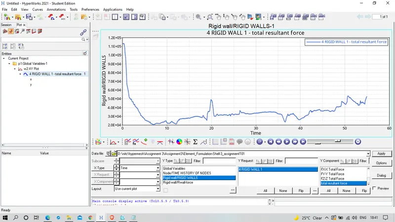 Figure 5
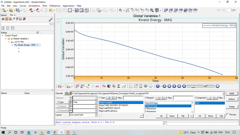 Figure 6
Kinetic Energy of a body can be calculated by using the formula (1/2)*m*v^2.
To know the total mass of components, Tools - mass details - mass,cog and inertia - check total mass.
mass (m)=503881.2817982854
To know the velocity , view - browsers - Hypermesh - solver - INIVEL - check velocity.
velocity = 15.6
Kinetic Energy = (1/2)*503881.281798254*(15.6)^2
= 61312274.37
Here the kinetic energy decreases due to decrease in velocity wrt time
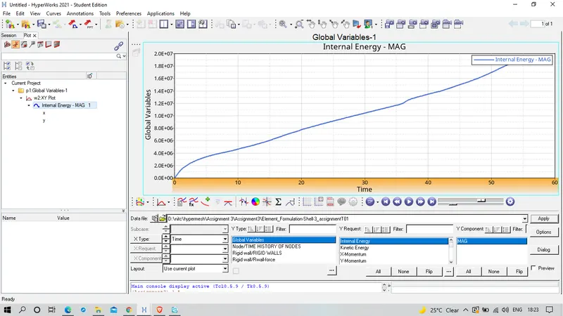 Figure 7
Internal energy = Heat energy `pm` work done
since deformation is increases wrt time work done increases, hence internal energy increases.
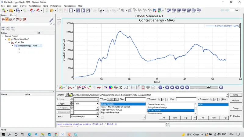 Figure 8
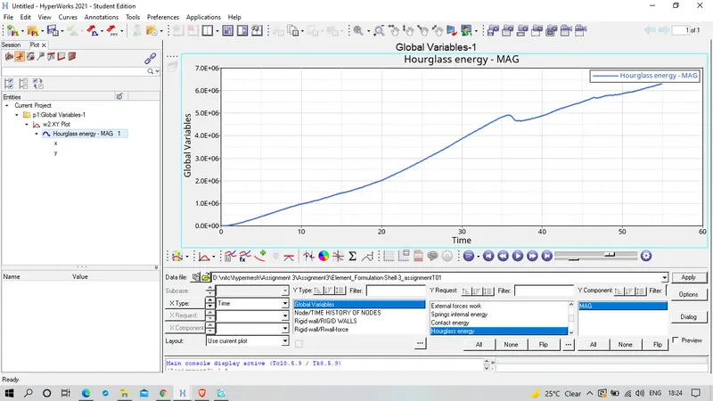 Figure 9
Hourglass Deformation: - For the under-integrated shell element, displacements and forces may exit for each node of the element, like the sum of all these forces and displacements give null strain and stress on the integration point of the element.
This problem exist only for under-integrated element.
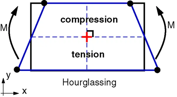
Typical hourglass deformation: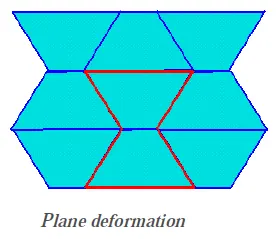
Hourglass energy, which is work done by the forces calculated to resist hourglassmodes, takes away from physical energy of the system.
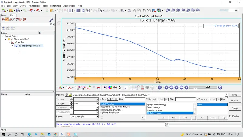 Figure 10
CASE2 SETUP AND PROCEDURE:
To change the shell element propeties, Model Browser - properties - edit the propertied with given recommended properties.
Recommended properties:
| Parameters | Comment | |
|
Ishell =24 |
QEPH 4 nodes shells are best combination of cost and accuracy. | |
|
Ismstr=2 |
Full geometric nonlinearities (default)with possible small strain formulation activation in RADIOSS Engine. | |
|
Ish3n=2 |
Standard 3 noded shell (C0)with modification for large rotation(default) |
|
| N=5 | Number of integration points set to 5 for accuracy bending. | |
|
Ithick=1 |
Thickness change is taken into account for accuracy. |
|
|
Iplas=1 |
Iterative plasticity for good accuracy. |
After changing the shell element properties by following the same procedure as above to run the simulation and to view aniamtion files by entering into the Hyperview and to plot the graphs enter into the Hyperworks Graph 2D and plot the graphs
Animation files are uploaded as video files
video1_after_properties_change.mkv
video2_after_properties_change.mkv
Plot results of the analysis are shown in figures 11,12 and 13
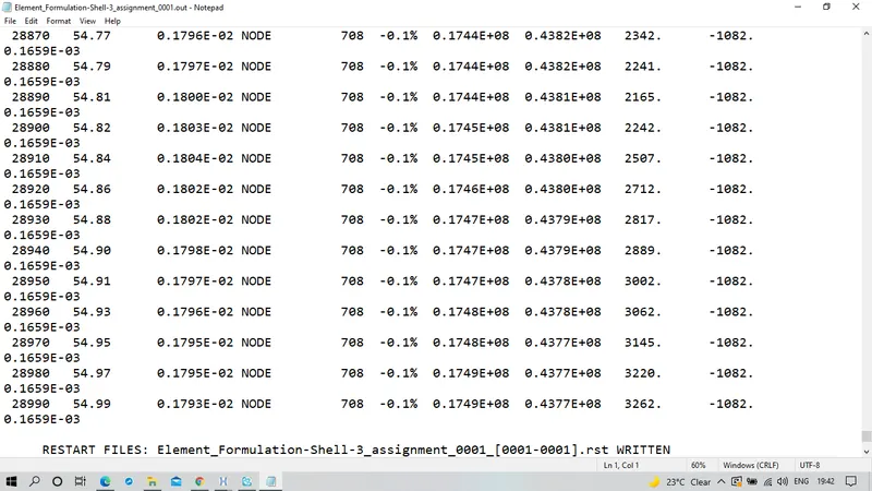 Figure 11
From the Figure 11, Energy error is 0.1% and mass error is 0.1659E-03 which are conpletely acceptable. 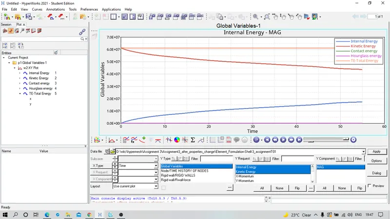
Figure 12
Here the Hourglass energy is zero because the QEPH 24 elements have integrated hourglass control mechanism to control the hourglass energy.
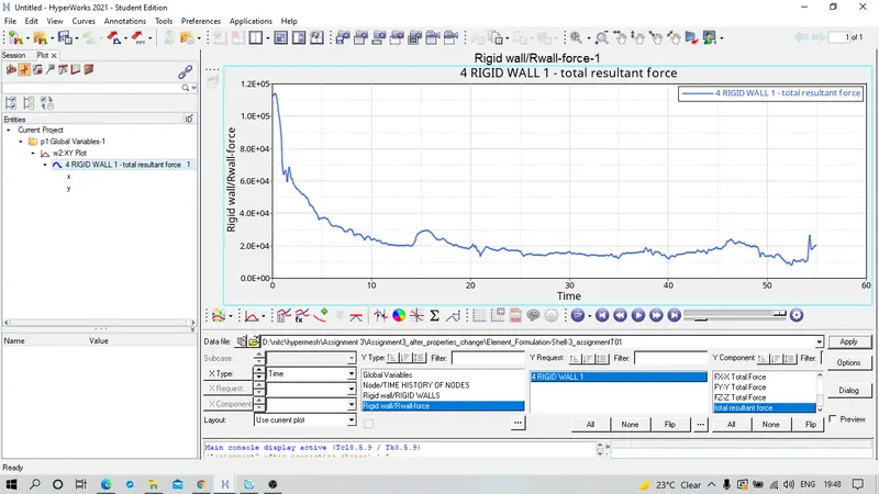 Figure 13
COMPARISON:
1) Energy Error and Mass Error
From the Figure 4 and 11, we can see that the Energy error in analysis are -10.3% and -0.1% in base simulation i,e Before shell element property change and After shell element property change, and there is no changes in Mass Error in both simulation before and after property change, The change in Energy error is because Q4 elements used in base simulation uses the Perturbation Method of Hourglass Control, whereas the modified simulation use of QEPH 24 elements which uses the Integrated Hourglass Energy contol.
Figure 14 and 15 shows variation in Hourglass energy in both Before and After shell element property change.
Figure 14, Hourglass energy before the properties change.
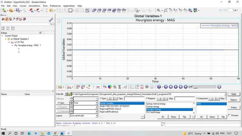 Figure 15, Hourglass energy after properties change.
2) Total Energy
Figure 16 and 17 shows the variation of Total energy before and after the shell element properties change.
Figure 16, Total energy before the shell element property change
 Figure 17, Total energy after the shell element property change.
Change in Total energy is due to change in Hourglass energy, Less Energy Loss after changing the shell element property changes due to ansence of Hourglass Energy.
RESULTS AND CONCLUSION : Successfully completed analysis for base simulation and after shell element properties change, I observed that after changing the shell element properties I get good results compared to that of base simulation and i able to know the important choosing required element formulation for respective problems.