Week-7 Head Impact
Aim: Pedestrian Head impact on the hood of automotive vehicle and finding the HIC factor comparing with head impact on rigid wall
Objective: To create a simulation of the head on rigid wall and head on the Hood using the given mesh, the simulation of the impact of head with rigid wall and how it absorbs energy and the simulation of the impact of head with Aluminum hood of elasto-plastic and how it absorbs energy. The simulation helps understand the simulation by testing simple head with rigid wall as first case and increasing the complexity by using the meshed foam head with accelerometer block with rigid wall and later, head foam with aluminium hood which of elasto-plastic material with initial velocity applied each simulation. To find the head injury co-efficient (HIC) should be found out.
Procedure:
- The given models are downloaded and is saved in the system.
- The model is used “Kg,mm,s” dimensions, accordingly the values of the velocity, length etc are given.
- The simple head model is taken.
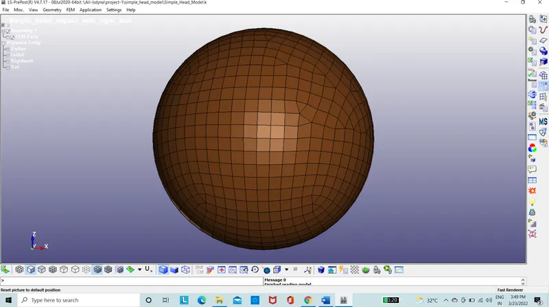
Figure 1: Simple head model
- The material is taken as steel.
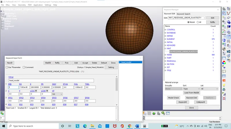
Figure 2: Material Id of Simple head model
- The section id is taken as 1.2mm as shell.
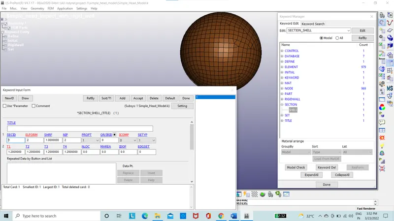
Figure 3: Section Id of Simple head model
- The part is input with the material Id and section Id.
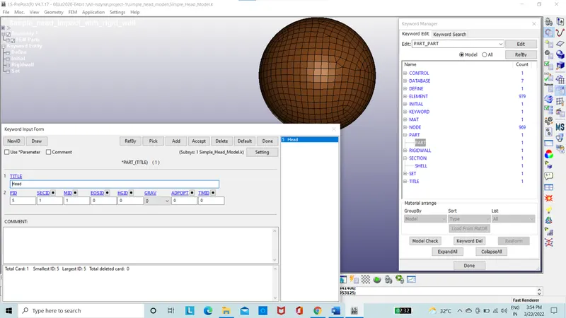
Figure 4: Part ID of Simple head model of Simple head model
- rigid wall was created at a distance of 25mm.
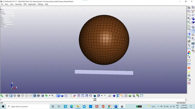
Figure 5: Rigid wall
- The initial velocity is put on the simple head model using the box option.
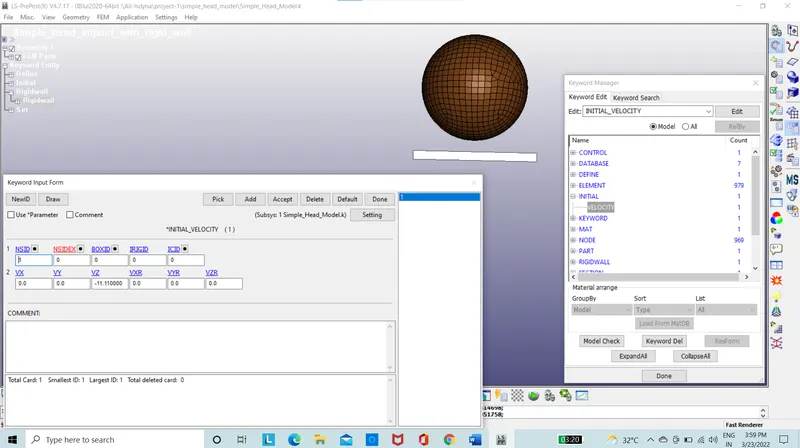
Figure 6: Initial velocity Input
- The termination time is also set to 10s.
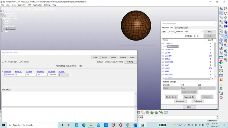
Figure 7: Termination time
- database is set for ASCII with GLSTAT, MATSUM, GLEOUT, RCFORC etc.
- Binary database as D3 plot.
- The termination time is set as 10s.
- The input file is run on Ls-run.
- The command file is run.
- The result file is obtained.
- The result of stress, energies etc are taken into consideration.
- The simple head model is now replaced with the head foam model given.
- The head foam model is copied on the folder and a fresh file is open in the Ls-prepost.
- In this empty file the transformation option in define is used and in Y-direction to 45 degree the model is rotated.
- In the include transformation the head foam is input and the trans ID is given.
- Later, empty file is saved as main_head_rigid. And open again.
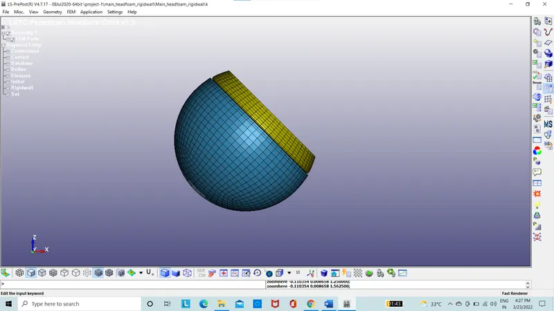
Figure 8: Head foam model
- The material is given and section is also given as solid section.
- Rigid wall was created at a distance of 25mm.
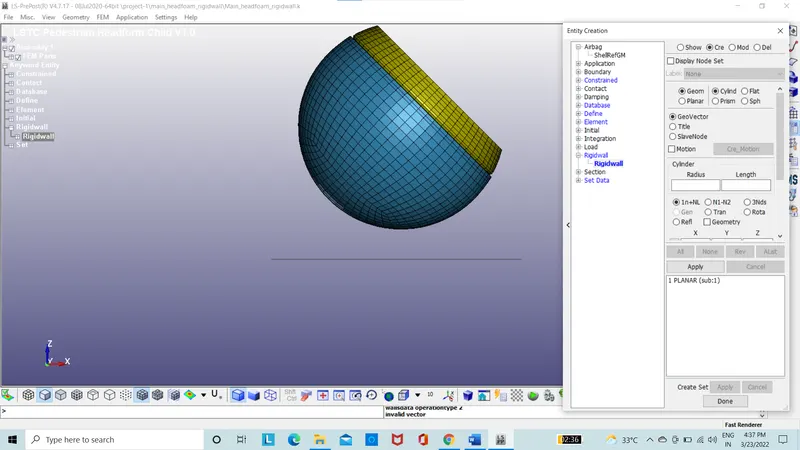
Figure 9: Rigid wall
- The initial velocity is put on the simple head model using the box option. Considering the velocity of 40 Km/h and its 11.11 mm/ms
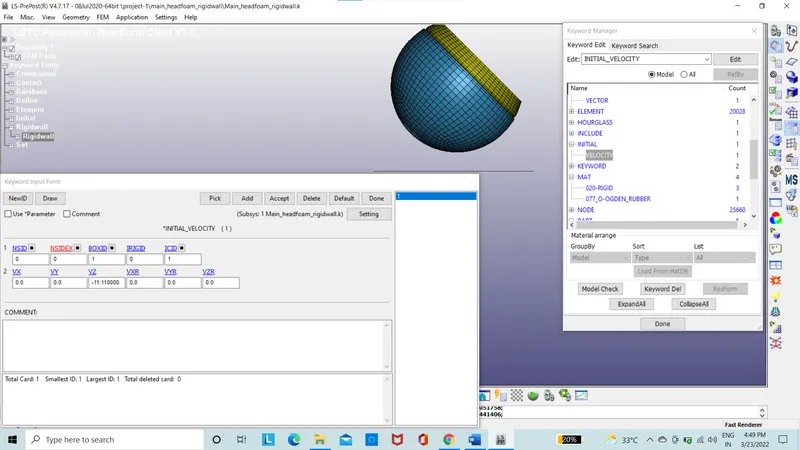
Figure 10: Initial velocity Input
- The termination time is also set to 13s.
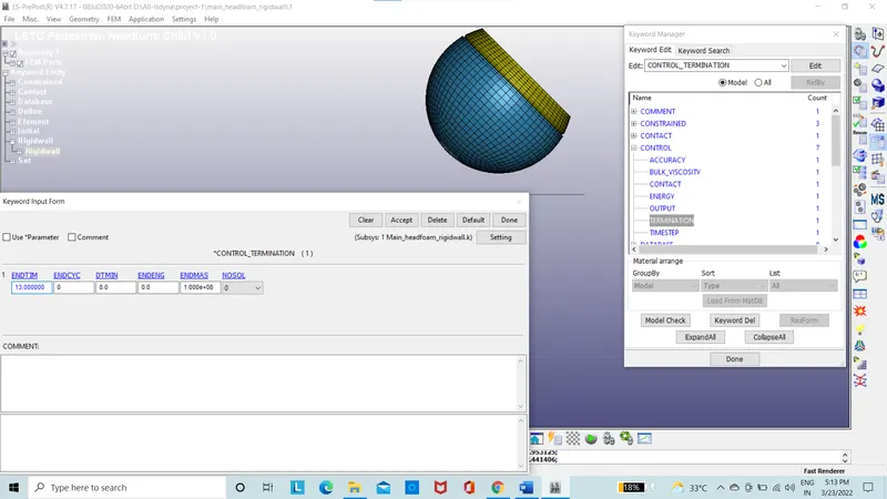
Figure 11: Termination time
- database is set for ASCII with GLSTAT, MATSUM, GLEOUT, RCFORC etc.
- Binary database as D3 plot.
- The termination time is set as 13s.
- The input file is run on Ls-run.
- The command file is run.
- The result file is obtained.
- The result of stress, energies etc are taken into consideration.
- The head foam model with rigid wall is replaced with head foam model with the meshed hood model.
- The head foam model and mesh hood is copied on the folder and a fresh file is open in the Ls-prepost.
- The meshed hood is opened and is assigned with the material as aluminium with elasto-plastic material properties.
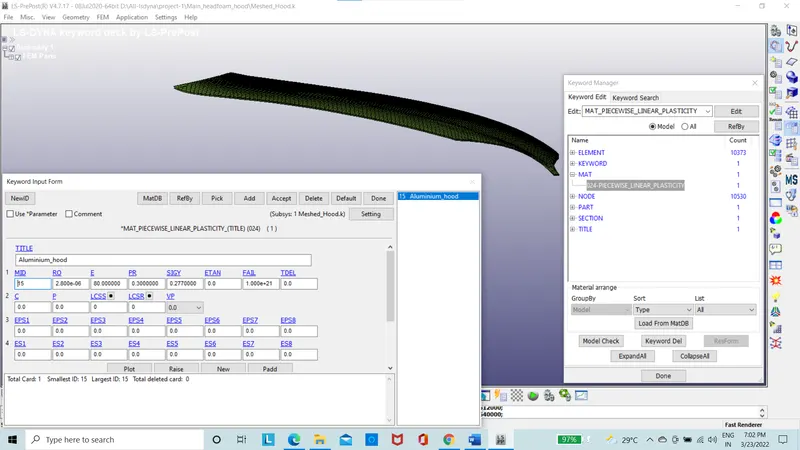
Figure 12: Meshed hood material properties
- The section property is assigned to the hood.
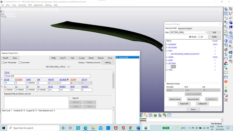
Figure 13: Meshed hood with thickness
- In this empty file the transformation option in define is used and in Y-direction to 45 degree the model is rotated.
- In the include transformation the head foam is input and the trans ID is given. Include option is to import the meshed hood model.
- Later, empty file is saved as main_head_hood. And open again.
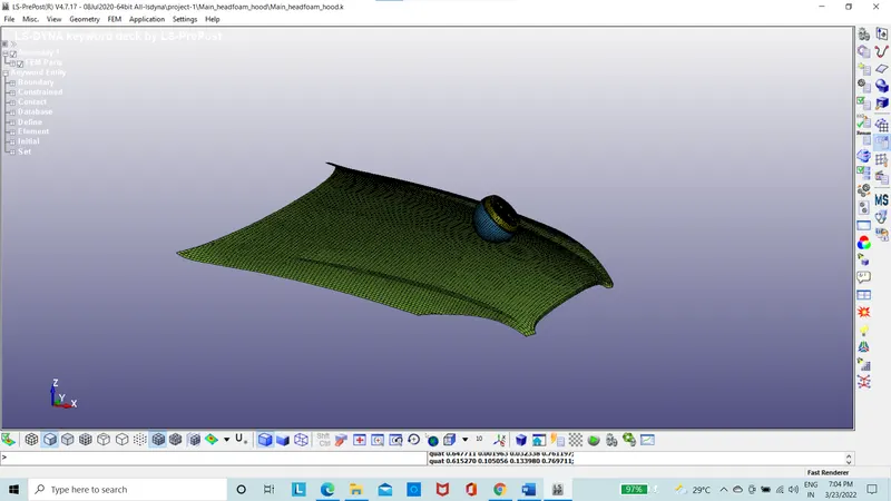
Figure 14: Head foam model and meshed hood
- The material is given and section is given as solid section.
- The initial velocity is put on the simple head model using the box option. The velocity is to taken in the X-direction at V(X)=11.11xCos (45) =5.83 mm/ms2
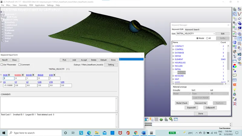
Figure 15: Initial velocity Input
- The termination time is also set to 50s.
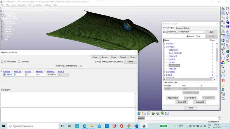
Figure 16: Termination time
- database is set for ASCII with GLSTAT, MATSUM, GLEOUT, RCFORC etc.
- Binary database as D3 plot.
- The termination time is set as 50s.
- The input file is run on Ls-run.
- The command file is run.
- The result file is obtained.
- The result of stress, energies etc are taken into consideration.
Results:
Case 1: The simple head with rigid wall
The simple head has the stress acting on it when the head fall on the rigid wall is 355 Mpa
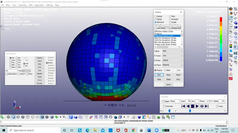
Figure 17: Von-misses stress for simple head model
The effective strain plot for the simple head model.
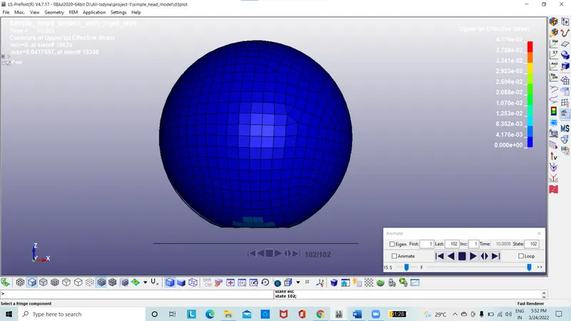
Figure 18: Von-misses stress for simple head model
The energy plot is taken and the internal, kinetic and total energy is plotted.
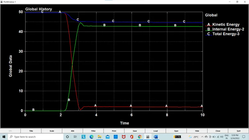
Figure 19: The energy plots for simple head model
Case 2: The head foam hitting the rigid wall
The head foam has the stress acting on it when the head fall on the rigid wall is 3.79 Mpa
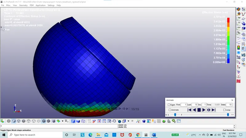
Figure 20: Von-misses stress for head foam model
The effective strain plot for the simple head model.
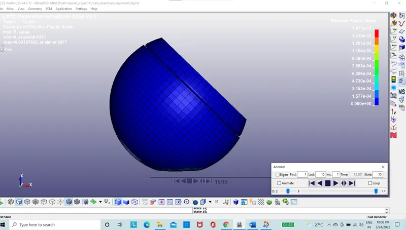
Figure 21: Von-misses stress for head foam model
The energy plot is taken and the internal, kinetic and total energy is plotted.
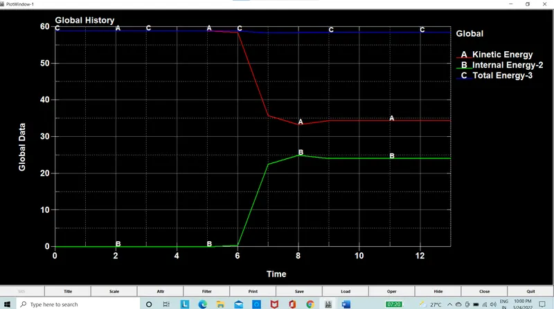
Figure 22: The energy plots for head foam model
The Hic value of foam head model is 3527
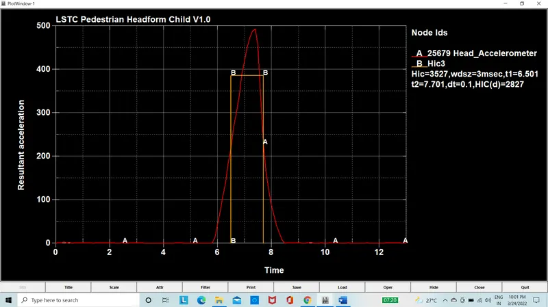
Figure 23: Hic Plot for Head foam hitting the rigid wall
The Hic value is cross verified by using the formula
`HIC=max/(t1t2) {(t1-t2)[1/((t2-t1)) int_(t2)^(t1) a(t)dt]^2.5 }`
HIC=(386)^2.5*1.2*10^-3=3512.76
HIC(d)=0.75446(free motion head foam HIC) +166.4
HIC(d)=0.75446*3512.76+166.4=2816.63
Which is close to the HIC value we have got from the simulation
Case 3: The head foam hitting the meshed Hood
The head foam has the stress acting on it when the head fall on the rigid wall is 277 Mpa
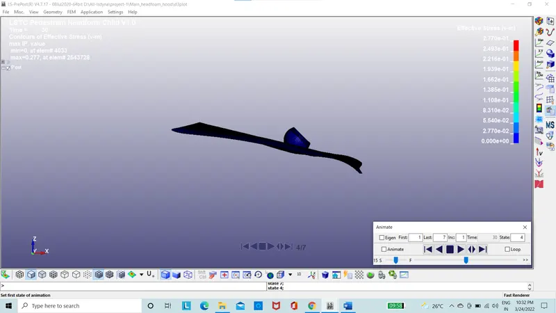
Figure 24: Von-misses stress for head foam model
The effective strain plot for the simple head model.
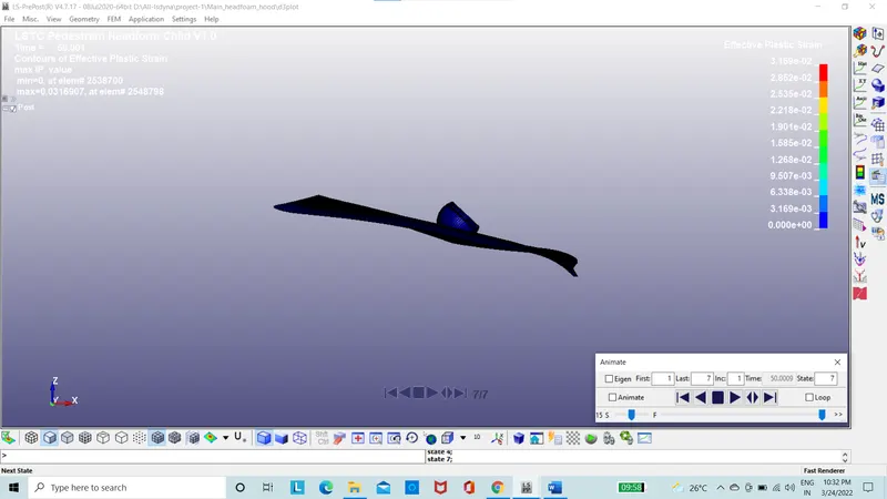
Figure 25: Von-misses stress for head foam model
The energy plot is taken and the internal, kinetic and total energy is plotted.
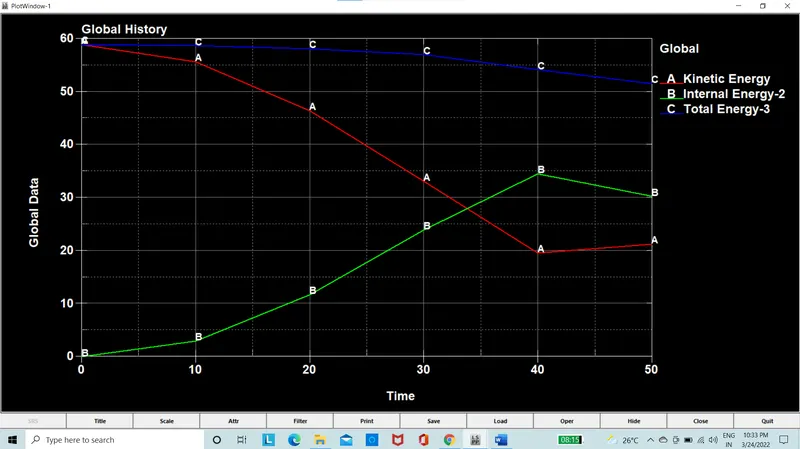
Figure 26: The energy plots for head foam model
The Hic value of foam head model is 33
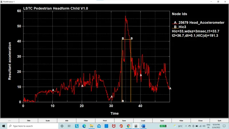
Figure 27: Hic Plot for Head foam hitting the rigid wall
The Hic value is cross verified by using the formula
`HIC=max/(t1t2) {(t1-t2)[1/((t2-t1)) ∫_(t1)^(t2)a(t)dt]^2.5 }`
HIC=(41.3)^2.5*3*10^-3=32.88
HIC(d)=0.75446(free motion head foam HIC) +166.4
HIC(d)=0.75446*32.88+166.4=191.20
Which is close to the HIC value we have got from the simulation
Conclusion:
The value of the HIC got from the simulation and the value calculated is having negligible variation which is acceptable and from that, conclusion is simulation is run properly.
The HIC value of the Case 3 is lower than that of the Case 2 is because the rigid wall which is undeform able is replaced by the deform able aluminium hood.