Week 3 - 2D meshing for sheet metal
Aim: Create mesh of 2D elements of given hood model for sheet metal
Objective: The given hood model of uniform thickness is taken as sheet metal which is to be meshed on by creating a mid-surface with 2D elements with given quality criteria and good mesh flow to be followed.
The following quality criteria:
- Target/Average length: 5
- Minimum length: 2
- Maximum length:7
- Aspect: 3
- Warpage: 5
- Skewness: 45
- Jacobian: 0.7
- Minimum quad angle: 45
- Maximum quad angle:135
- Minimum tria angle:30
- Maximum tria angle:120
- Tria percentage:15
Procedure:
- Download the given model which is in the “.stp” format which is imported in the Ansa software, saved as ANSA format.
- The model is then oriented to the grey coloration for better normal using the orient option in topo module.
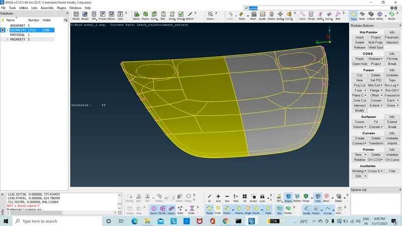
Figure 1: Before orientation
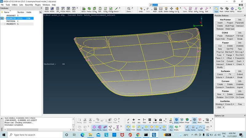
Figure 2: After orientation
- The geometry is checked for the errors using the “Checks manager” and using the release option in the cons we can clear the errors found, the hot points are deleted and the geometry is corrected using the topo option.
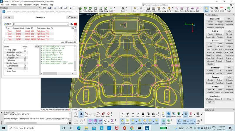
Figure 3: Before cleanup
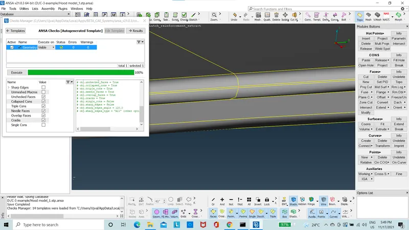
Figure 4: After cleanup
- The geometry is divided into four parts, the outer part, the inner part, the latch and the hinges, by using the “property” option view the parts accordingly.
- Using the “offset” option in topo module, obtain the mid surface of the outer part model, after measuring the thickness of the component, a value of “0.75/2” mm is assigned to the mid surface of the outer part. The new property is assigned using the “set PID” to outer part created with the thickness as 0.75 mm.
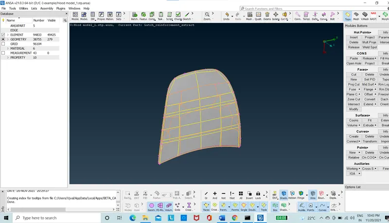
Figure 5: Outer part mid-surface
- Similarly using the “offset” option in topo module, obtain the mid surface of the inner part model, after measuring the thickness of the component, a value of “0.75/2” mm is assigned to the mid surface of inner part. The new property is assigned using the “set PID” to inner part created with the thickness as 0.75 mm.
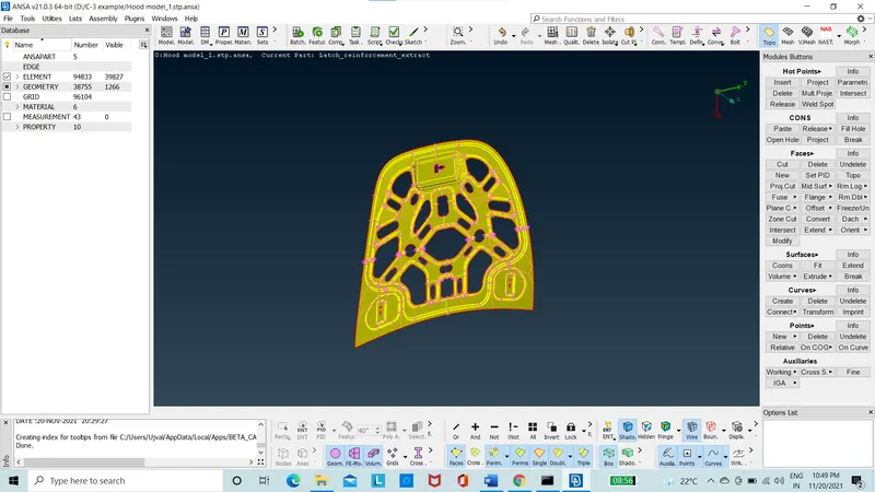
Figure 6: Inner part mid surface.
- Similarly using the “offset” option in topo module, obtain the mid surface of the “latch” part model, after measuring the thickness of the component, a value of “1.2/2” mm is assigned to the mid surface of inner part. The new property is assigned using the “set PID” to inner part created with the thickness as 0.1.2 mm.
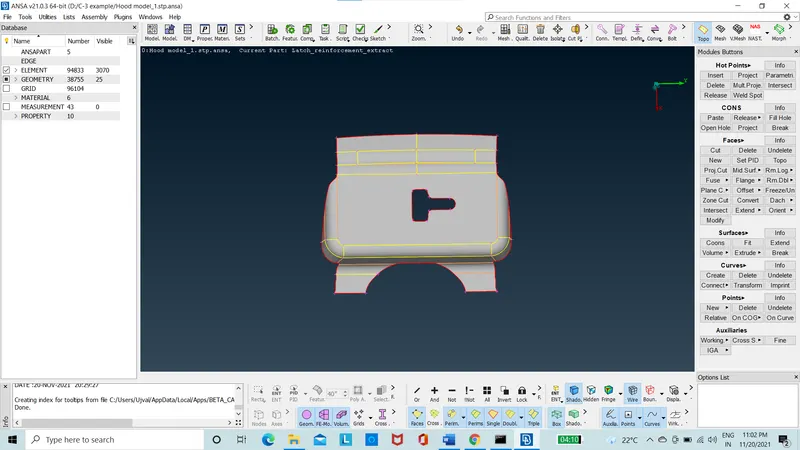
Figure 7: latch part mid surface.
- Similarly using the “offset” option in topo module, obtain the mid surface of the hinge parts model, after measuring the thickness of the component, a value of “1.2/2” mm is assigned to the mid surface of inner part. The new property is assigned using the “set PID” to inner part created with the thickness as 1.2 mm.
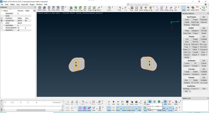
Figure 8: hinge part mid surface.
- The mid surfaces are again checked for the any errors like triple cons in the checks geometry and corrected all the errors by releasing the cons and deleting the hot points, rebuilt using the topo option.
- The mid surface of the outer hood is taken and meshed by avoiding rotating quads and opposite trias. Material is assigned as mild steel as default.
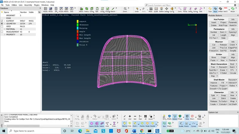
Figure 9: Outer hood part meshed
- The mid surface of the inner hood is taken and meshed avoiding rotating quads and opposite trias. Material is assigned as mild steel as default.
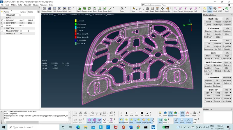
Figure 10: Inner hood meshed
- The mid surface of the latch is taken and meshed avoiding rotating quads and opposite trias. Material is assigned as mild steel as default.
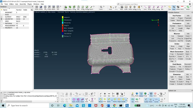
Figure 11: Latch meshed
- The mid surface of the hinges is taken and meshed avoiding the rotating quads and opposite trias. Material is assigned as mild steel as default.
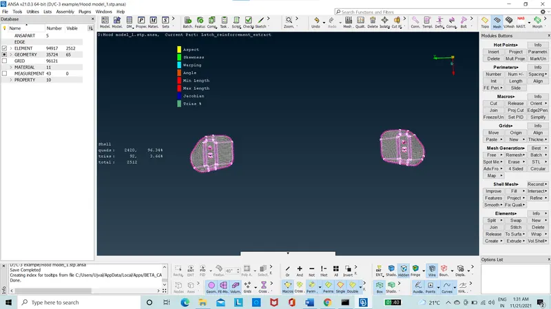
Figure 12: hinges part meshed.
- The model is saved with all the meshed parts created according to the above quality criteria.
- The model is set as “Draw shell as solid” option using the quality criteria-presentation parameters and saved.
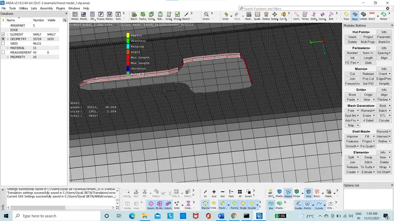
Figure 13: Draw shell as solid.
Conclusion:
In this project, mesh was created on the hood model with good mesh flow and the given specification of quality criteria was followed by avoiding the rotating quads and the opposite trias. The hood model was opened in the ANSA 21.0.3. Cleanup of geometry was performed. Mid-surface was extracted, defeaturing was performed and also assigned with respective thickness. The mesh created was with 94917 elements with no “OFF” elements present.
New points learnt(learning outcomes):
How to Clean up geometry.
How to defeature the geometry.
How to use macro area.
How to use “set PID”.
Understanding rotating quads and fix the geometry for proper mesh flow.
Understanding opposite trias and fix the geometry for proper mesh flow.
Creating proper mesh without “OFF” elements.
How to draw shell as solid