Week-7 Head Impact
PROJECT-1 Head Impact
OBJECTIVE:-
To perform the analysis of head impact and calculate the HIC (Head injury criteria/coefficient) Value:
Case 1 : Simple-head and rigid wall
Case 2: Head foam and rigid wall
Case 3: Head foam and meshed hood
INTRODUCTION:-
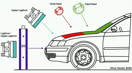
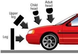
Pedestrian protection CAE is a part of vehicle safety engineering from a crash perspective. In pedestrian protection, we look for imparting minimum injury to head, upper leg (thigh), and lower leg (including knee) in case of an accident with a human subject. These tests are usually done at a lower velocity from 20-40 kmph as accidents tend to result in more severe circumstances above these velocities and braking in case of an accident often results in collision at low velocities.
Many pedestrian crashes involve a forward moving car (as opposed to cars and other vehicles with a vertical hood/bonnet). In such a crash, a standing or walking pedestrian is struck and accelerated to the speed of the car and then continues forward as the car brakes to a halt. most of the fatal injuries occur due to interaction with the car.
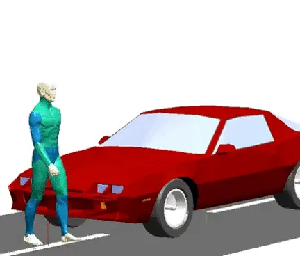
Vehicle designers usually focus on understanding the car-pedestrian interaction, which is characterized by the following sequence of events: the vehicle bumper first contacts the lower limbs of the pedestrian, the leading edge of the hood hits the upper thigh, and the head and upper torso are struck by the top surface of the hood and/or windshield.
HIC (Head Injury Criteria/Head Injury Coefficient):-
The head injury criterion (HIC) is a measure of the likelihood of head injury arising from an impact. The HIC can be used to assess safety related to vehicles, personal protective gear, and sport equipment. Normally the variable is derived from the measurements of an accelerometer mounted at the center of mass of a crash test dummy's head, when the dummy is exposed to crash forces.
Crash safety engineers consider the head which is more prone to injury that could lead to concussions or even death to be their main priority during crash analysis.
The factor that is used by engineers to determine the level of damage imparted onto the head region is determined using the HIC factor which stands for Head Injury Criterion / Coefficient.
Normally the variable is derived from the measurements of an accelerometer mounted at the centre of a crash dummy's head, when the dummy is exposed to crash forces.
Generally, it is defined by

where t1 and t2 are the initial and final time period chosen to maximize HIC and a is the accelaration over the period of time from t1 to t2.
UNIT SYSTEM:- kg mm ms
PROCEDURE:-
CASE-1:- Simple head model impacting against rigid wall
In the first case, a sphere shaped shell element is used as a simple head model and made to impact on a rigidwall.
1) Defining INCLUDE Keyword:-
Firstly a new Main or Parent .k file is created having only single keyword defined thet is INCLUDE. keyword INCLUDE is defined in order to include the child file into the main file so that better readability and organisation of files can be ensured.
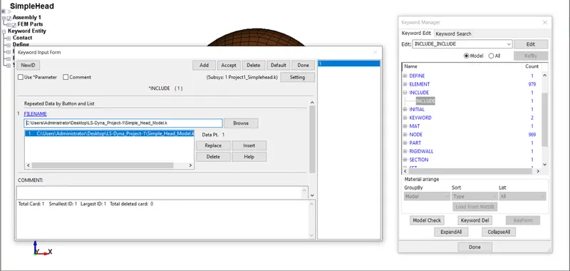
Then this main .k file is saved and opened again now we can see the parts contained by the same file that we included in our main .k file.
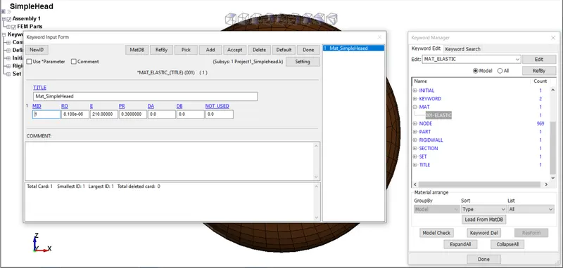
2) Defining Material:- ELASTIC material is defined here for the simplehead as shown in the image below.
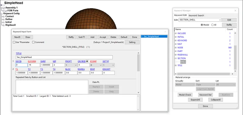
3) Defining Section:- SHELL section is defined here for the simplehead with ELFORM=16 and THICKNESS(T)=1.5mm as shown in the image below.
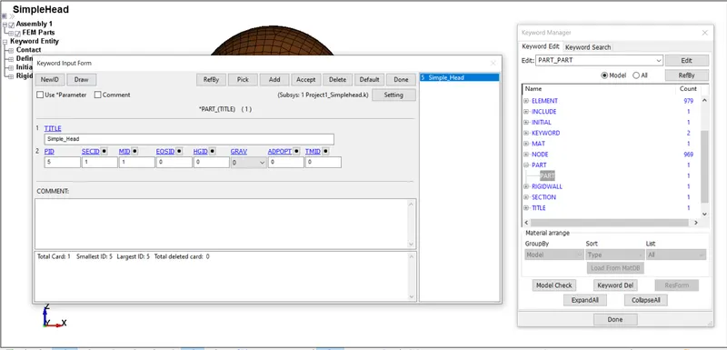
4) Assigning Section and Material to the Part:- Material and Section properties are assigned to the part.
5) Creating Vector and Rigidwall:-
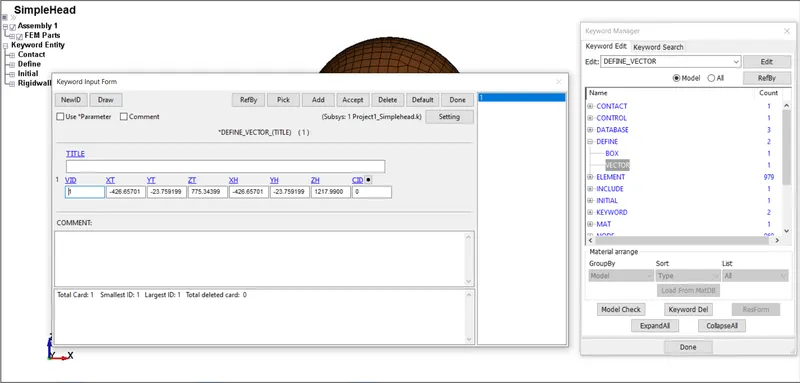
Vector:- A vector is created to define the normal direction of the rigidwall. This is important because the vector normal of rigidwall should be facing the coming object otherwise the rigidwall would not detect the object nodes, hitting the rigidwall and also this is the reason that we do not need to define a seperate contact for object and rigidwall because defining vector direction of rigidwall normal is enough in this case for rigidwall to detect the object.
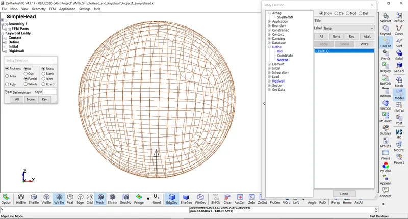
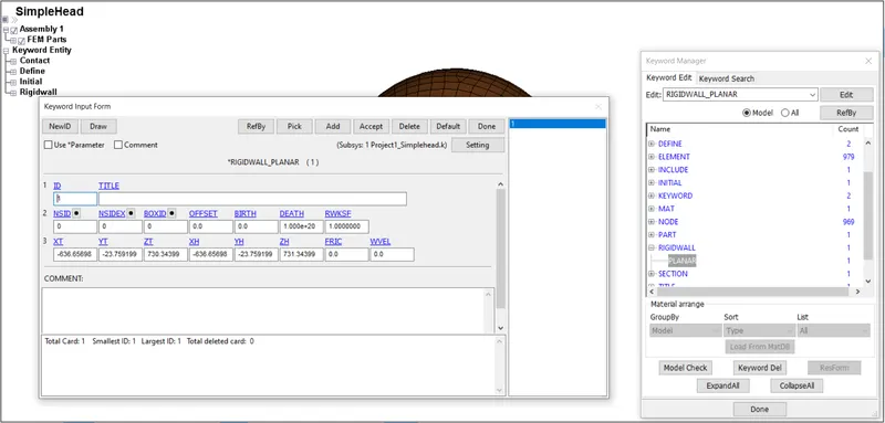
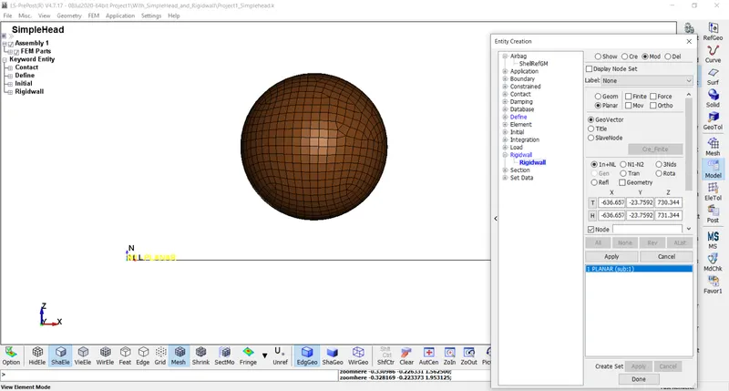
RigidWall:- Rigid wall definitions have been divided into two separate sections, PLANAR and GEOMETRIC. Planar walls can be either stationary or moving in translational motion with mass and initial velocity. The planar wall can be either finite or infinite. Geometric walls can be planar as well as have the geometric shapes, such as rectangular prism, cylindrical prism and sphere. Rigidwall is not any physical wall or FEA entity but it is just an analytical wall with infinite stiffness ie. non deformable.
The distance between sphere and rigidwall is 45mm.
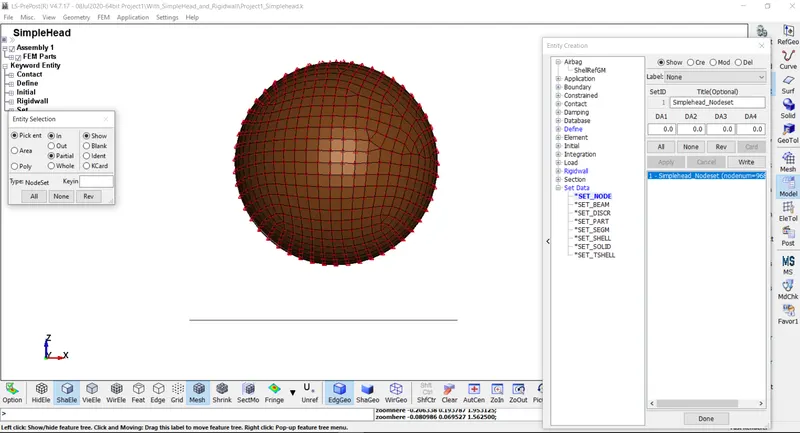
6) Creating NodeSet:- A nodeset is created out of the simplehead part given with a specific nodeset id.
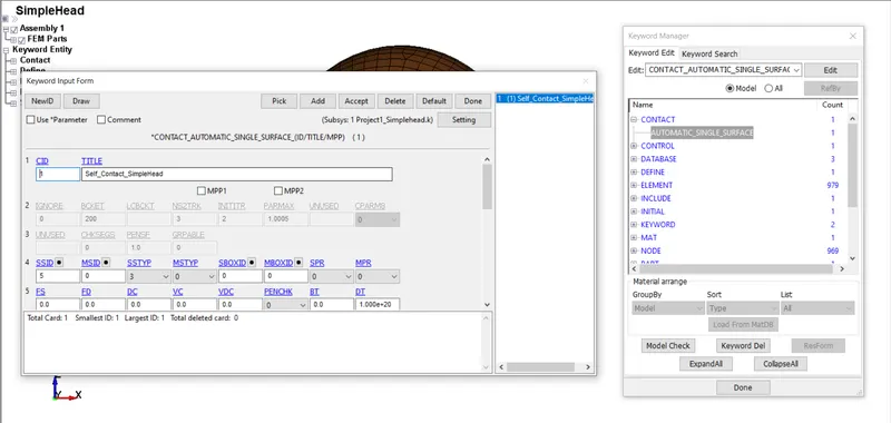
7) Defining Contact:- A contact card AUTOMATIC_SINGLE_SURFACE is defined to encounter self contact situation if occurs.
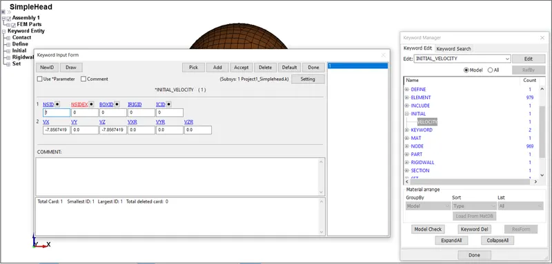
8) Defining Initial Velocity:- Initial velocity is given as 40km/hr or 11.11mm/ms in this case. Components of velocity in -X and -Z directions are given as input here to ensure the motion of the sphere in XZ plane.
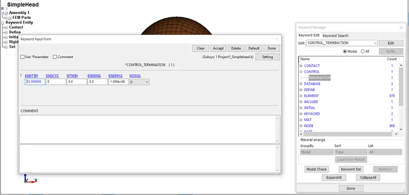
9) Defining Termination Time:- Termination time for the simulation can be defined in CONTROL_TERMINATION card. A total time of 12ms is specified for the simulation.
10) Defining Outputs:- Outputs that are required can be defined using DATABASE Keyword.
*DATABASE_ASCII:- GLSTAT, MATSUM are defined here in this case.
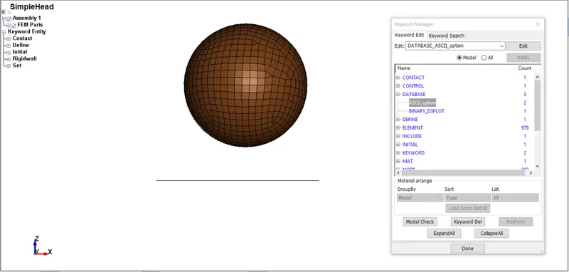
*DATABASE_D3PLOT:- 0.5ms is given as time step in this card.
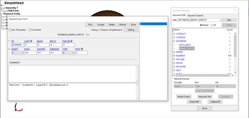
Now save this .k file and run in LS-Run. It should give Normal Termination to move towards postprocessing.
Simulation:-
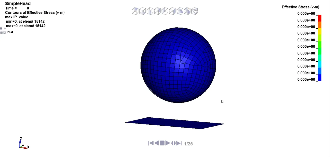
Energy Plot:-
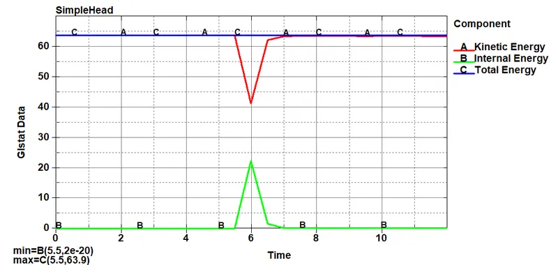
It can be seen that when the Simplehead hits the rigid wall, there is a reduction in the kinetic energy of the Simplehead while there is an increment of the internal energy of the wall and after that both energies become constant. This validates the principle of conservation of energy which states that energy can neither be created nor destroyed but can be converted from one form of energy to another.
CAES-2:- Pedestrian headfoam model impacting against rigidwal
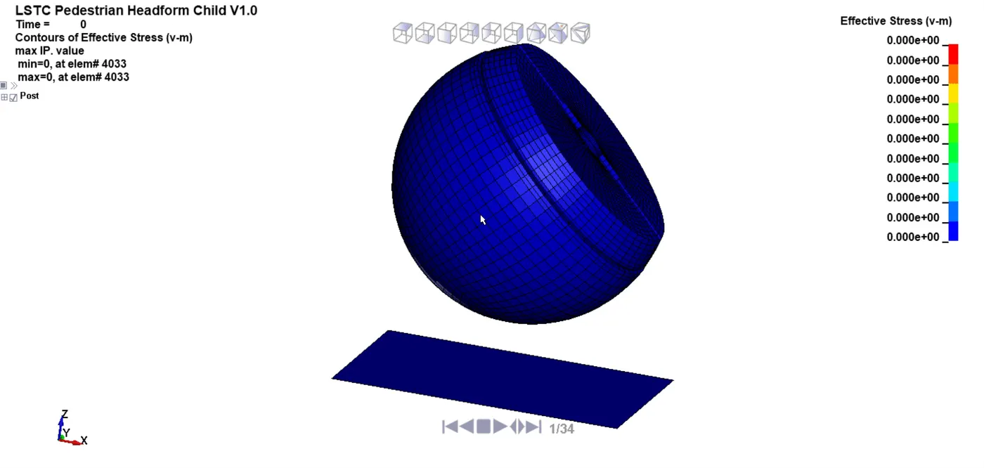
In the second case, a child headform model is used as a head model and made to impact on a rigidwall.
Unlike the previous case, where the head part was a complete sphere, this model involves translation and rotation of the part hence creating an impact angle of 45 degrees with the rigid wall and the bonnet. This can be done using the *INCLUDE_TRANSFORM and *DEFINE_TRANSFORMATION keywords in a separate keyword file and referenced to the headfoam model using the above-mentioned keywords such that any changes made don't directly affect the headfoam model which can act as a basis for all pedestrian safety analysis.
1) Defining DEFINE_TRANSFORMATION Keyword:-
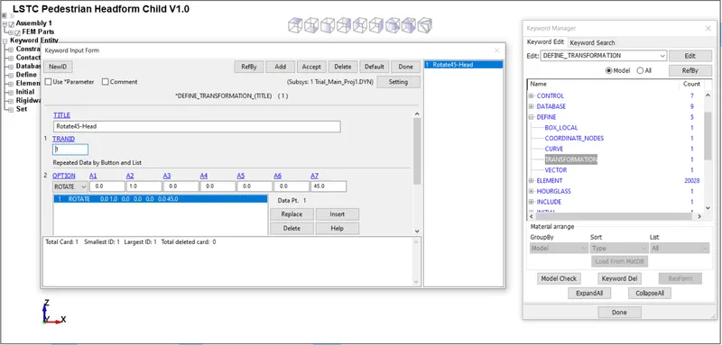
Firstly a new Main or Parent .k file is created having only single keyword defined thet is DEFINE_TRANSFORMATION. This keyword is defined in order to specify the transformation that has to be performed with the headform and here we have to rotate the headform by 45 degree angle.
This keyword has to be initialized before the INCLUDE_TRANSFORM to prevent errors. This keyword lets us perform certain transformations like SCALE, ROTATE, etc to the part file reference in the INCLUDE keyword.
For our model, we will rotate the model about the x-axis at an angle of 45 degrees. This can be achieved by specifying the A1-A3 parameters which define the axis of rotation and A4-A6 the point through which the vector passes through and finally A7 where the angle of rotation in degrees can be specified.
A1, A2, A3 = Parallel to X, Y, Z Axis
A4, A5, A6 = Through Point
A7 = Angle
2) Defining INCLUDE_TRANSFORM Keyword:-
This Keyword is used to include a child .k file into the main file after performing the transformations with them using TRANID. Basically we can include the child file into the main file so that better readability and organisation of files can be ensured.
This keyword is a modified form of the regular *INCLUDE_INCLUDE keyword file, that it helps us make changes/ transform the imported model prior to creating it on the viewport.
Certain offsets of IDs can also be changed however since our model consists of very few parts we will not use the offset command.
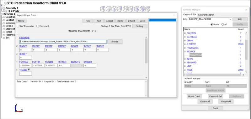
Then this main .k file is saved and opened again now we can see the parts contained by the same file that we included in our main .k file. here we can see the included part with transformation performed on it.
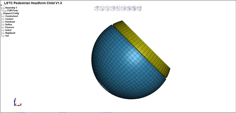
- A planar rigidwall is created such that the pedestrain headfoam model impacts the rigidwall at an angle 45 deg and placed at an appropriate distance from it.The normal direction of the rigidwall is ensured to be against the velocity input direction.
- Since this headfoam part constitutes of different sub-parts, each sub-parts are modeled using different materials with the Skull, Accel block, Backplate modeled using a MAT_20_RIGID material, and the Skin with a MAT_77_O-OGDEN_RUBBER which is a type of hyperelastic material.
- The headfoam part which has to replicate the behavior of a real pedestrian head is modeled using a SECTION_SOLID with default solid element formulation.
- *CONTACT_AUTOMATIC_SURFACE_TO_SURFACE card is established between Skin and Skull parts as they undergo physical contact during the impact simulation.
3) Defining Box for the Headform:- A Box is created around the headform so that collectively, velocity can be given for this headform since it contains 4 individual parts.
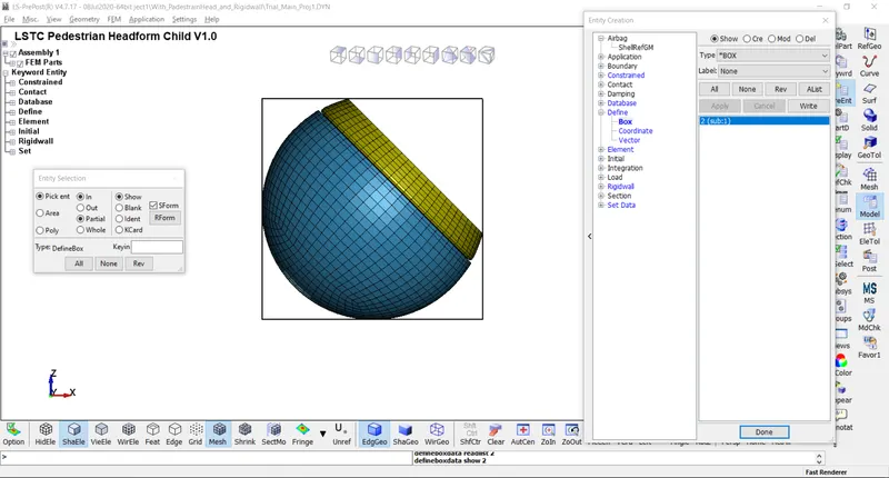
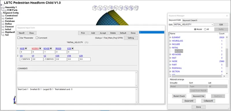
4) Defining Initial Velocity:- Initial velocity is given as 40km/hr or 11.11mm/ms^2 in this case to the box. Components of velocity in -X and -Z directions are given as input here to ensure the motion of the sphere in XZ plane.
5) Defining Termination Time:- Termination time for the simulation can be defined in CONTROL_TERMINATION card. A total time of 16ms is specified for the simulation.
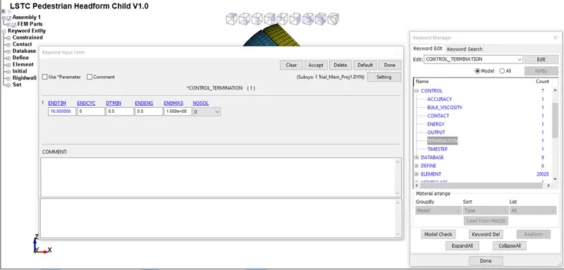
6) Defining Outputs:- Outputs that are required can be defined using DATABASE Keyword.
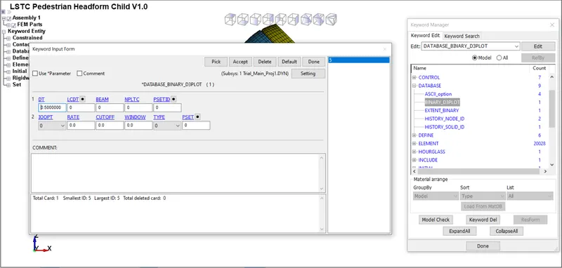
*DATABASE_BINARY_D3PLOT:- It is used to get the outputs. Time step should be given as 0.5ms.
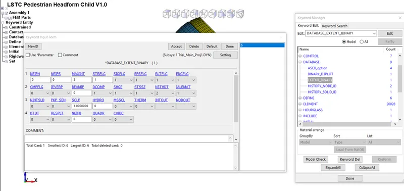
*DATABASE_EXTENT_BINARY:- It is used to compute elastic strain in the model and some of the strain data. STRFLG should be given as 1.
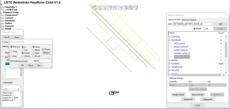
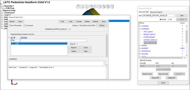
*DATABASE_HISTORY_SOLID_ID:- It is used to compute stress/strain in the model at 3289th Element.
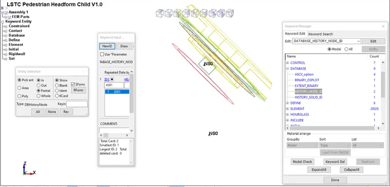
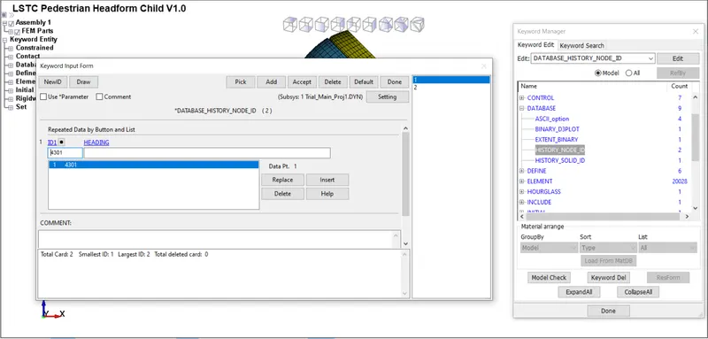
*DATABASE_HISTORY_NODE_ID:- It is used to compute acceleration in the model at 4309th Node.
*DATABASE_ASCII_option:- The time step value of 0.5ms is given for GLSAT, MATSUM, ELOUT, NODOUT.
Now save this .k file and run in LS-Run. It should give Normal Termination to move towards postprocessing.
Simulation:-
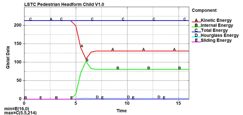
Energy Plot:-
It can be seen that when the Simplehead hits the rigid wall, there is a reduction in the kinetic energy of the Simplehead while there is an increment of the internal energy of the wall and after that both energies become constant. This validates the principle of conservation of energy which states that energy can neither be created nor destroyed but can be converted from one form of energy to another.
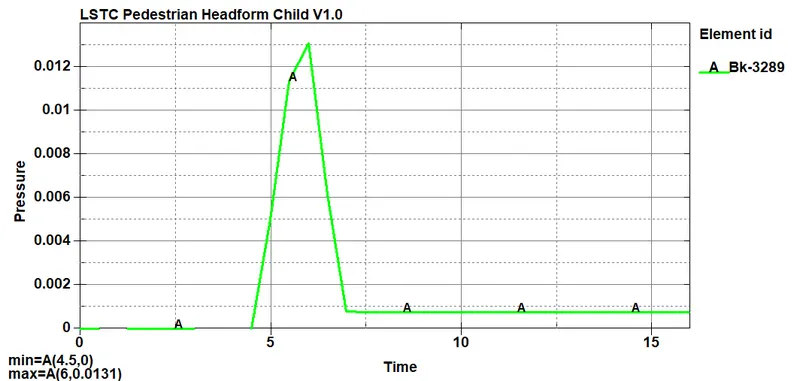
Pressure Plot:-
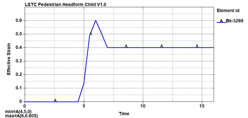
Strain Plot:-
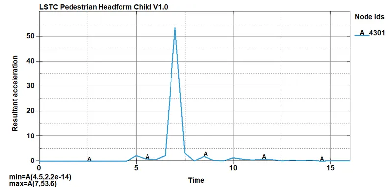
Resultant Acceleration Plot:-
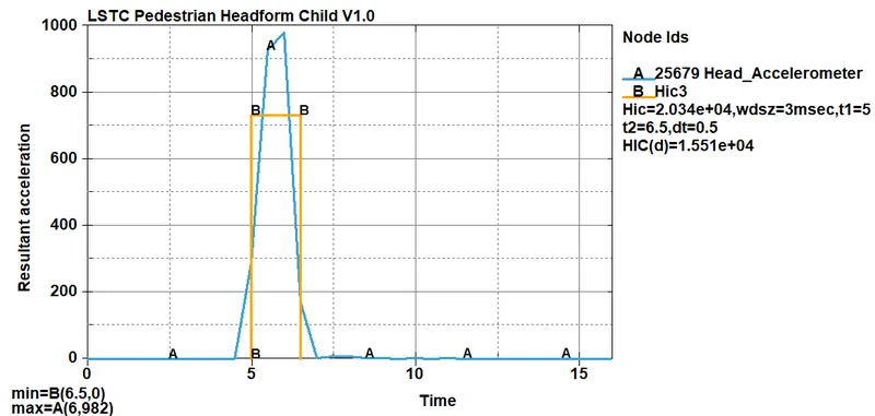
HIC Plot:-
CASE-3:- Pedestrian headfoam model impacting against rigid hood
In the third case, a child headform model is used as a head model and made to impact on a hood model.
Model-1 Headform
Headform is a complete model with all the keywords defined already so we do not need to additionally define any of the keywords and we can use this model as it is.
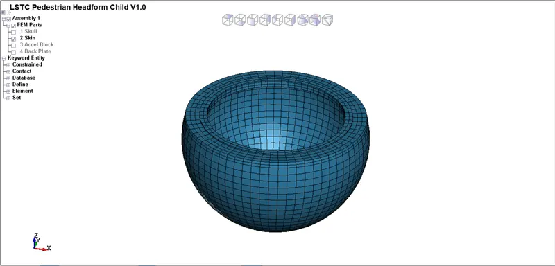
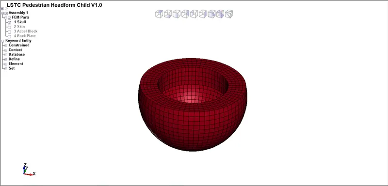
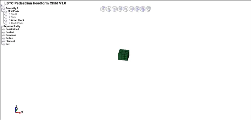
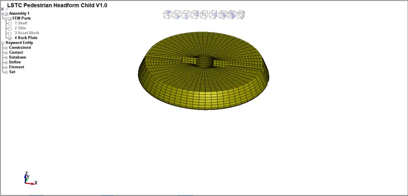
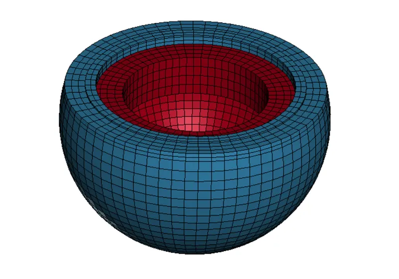
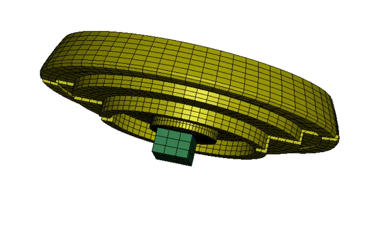
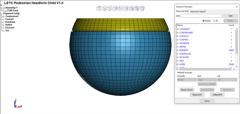
Headform model consists of total 4 individual parts-
1) Skin 2) Skull 3) Accel Block 4) Back Plate
Model-2 Hood
Material and Section are to be defined and to be assigned to the hood part in this hood model.
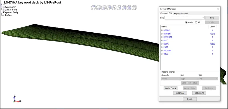
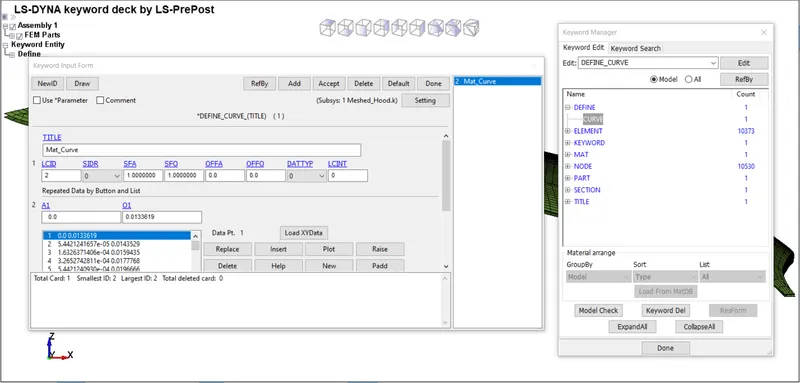
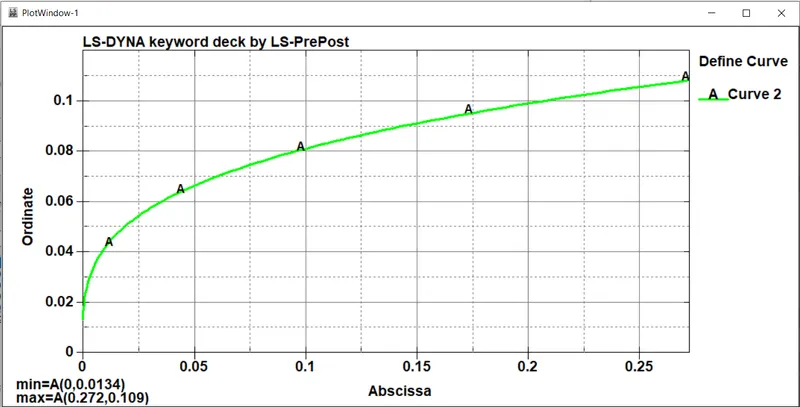
1) Defining Curve for Material:- A curve is defined for hood material.
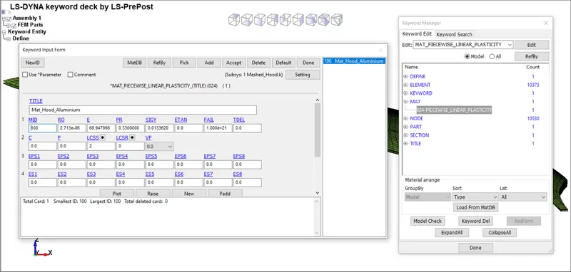
2) Defining Material for Hood:- Aluminium is defined as hood material using PIECEWISE_LINEAR_PLASTICITY card.
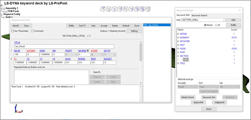
3) Defining Section for Hood:- Shell section is defined for hood under SECTION_SHELL card.
4) Defining DEFINE_TRANSFORMATION Keyword:-
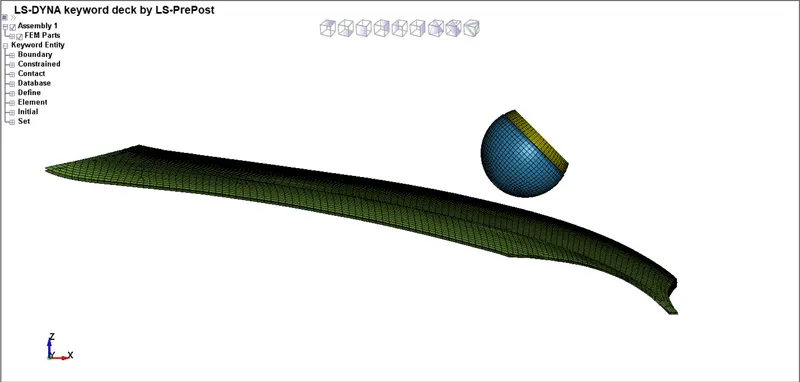
DEFINE_TRANSFORMATION and INCLUDE_TRANSFORM card is defined in the same way shown in the case-2 mentioned above.
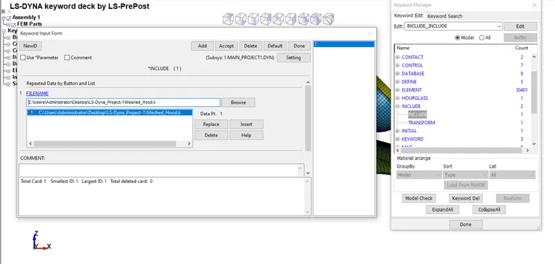
5) Defining INCLUDE Keyword:- INCLUDE keyword is defined to retrieve the .k file of hood model into the main .k file.
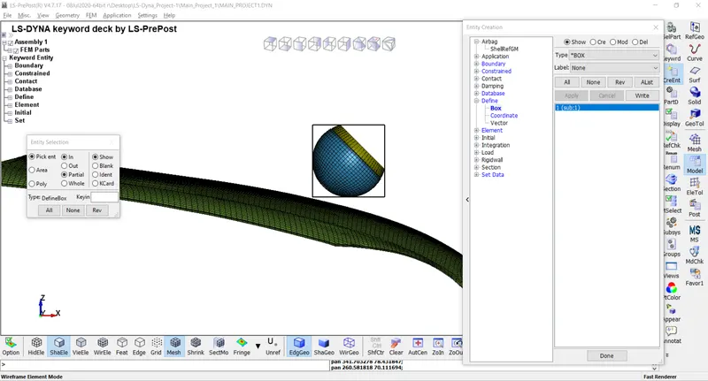
6) Defining Box for Headform Model:- A Box is created around the headform so that collectively, velocity can be given for this headform since it contains 4 individual parts.
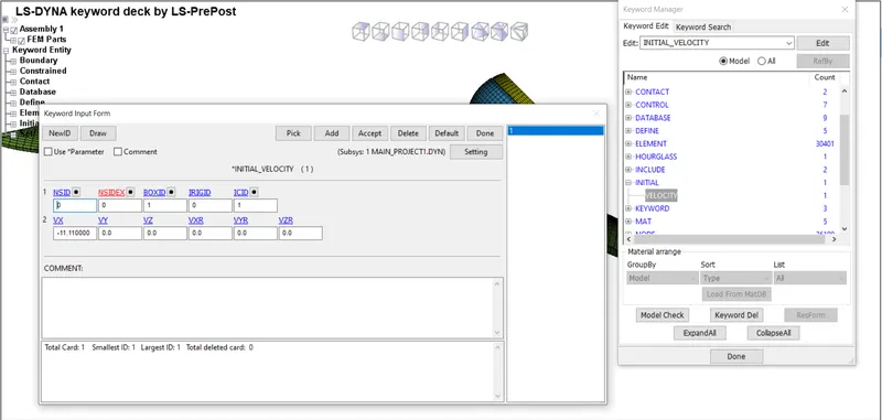
7) Defining Initial Velocity:- Initial velocity is given as 40km/hr or 11.11mm/ms^2 in this case to the box in the form of BOXID. Local Co-ordinates ID(ICID) is given as input here to ensure the motion of the sphere in XZ plane.
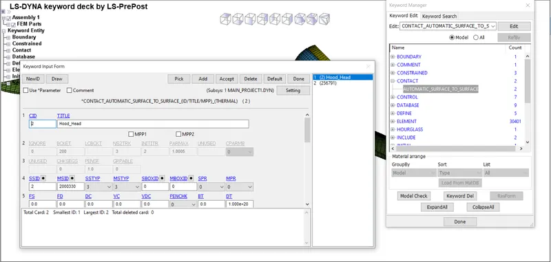
8) Defining Contact:- Contact is defined between the skin and the hood parts using AUTOMATIC_SURFACE_TO_SURFACE card where hood part is defined as master and skin part is defined as slave.
9) Creating SPC_SET:-
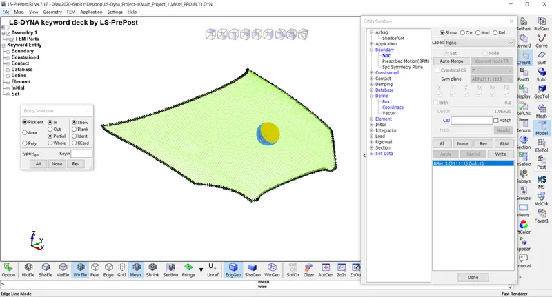
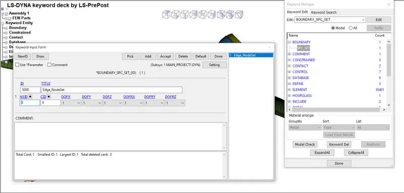
A single point constrained set is created by defining nodes present at the hood edge, motion of which is constrained in all the directions in order to specify boundary condition for hood in this simulation.
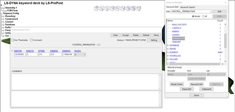
10) Defining Termination Time:- Termination time for the simulation can be defined in CONTROL_TERMINATION card. A total time of 20ms is specified for the simulation.
6) Defining Outputs:- Outputs that are required can be defined using DATABASE Keyword.
*DATABASE_BINARY_D3PLOT:- It is used to get the outputs. Time step should be given as 0.2ms.
*DATABASE_EXTENT_BINARY:- It is used to compute elastic strain in the model and some of the strain data. STRFLG should be given as 1.
*DATABASE_HISTORY_SOLID_ID:- It is used to compute stress/strain in the model at 3289th Element.
*DATABASE_HISTORY_SOLID_ID:- It is used to compute acceleration in the model at 4309th Node.
*DATABASE_ASCII_option:- The time step value of 0.2ms is given for GLSAT, MATSUM, ELOUT, NODOUT.
Now save this .k file and run in LS-Run. It should give Normal Termination to move towards postprocessing.
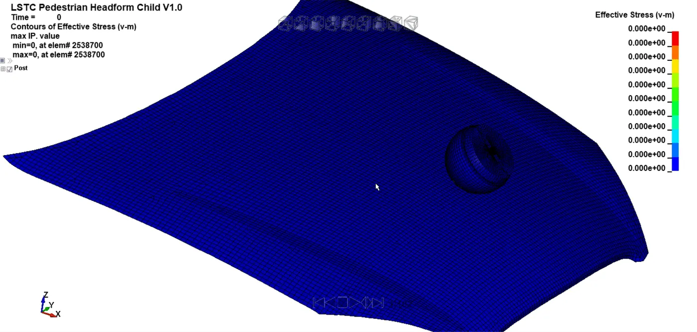
Simulation:-
RESULTS:-
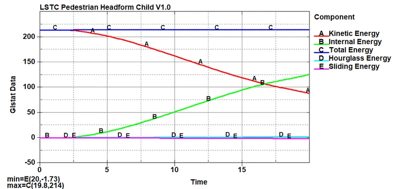
Energy Plot:-
It can be seen that when the Simplehead hits the rigid wall, there is a reduction in the kinetic energy of the Simplehead while there is an increment of the internal energy of the wall and after that both energies become constant. This validates the principle of conservation of energy which states that energy can neither be created nor destroyed but can be converted from one form of energy to another.
Pressure Plot:-
Case-2
Case-3
Comparision:-
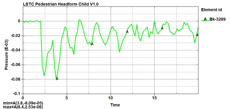
In the case of rigidwall since the rigidwall is non deformable, it impacts harder so the pressure reaches to 13.1MPa max. pressure at 6ms. During pedestrian head impact, the skin part of the head developes major amount of stress as it impacts the rigidwall at a short period of time. From the Pressure plot, it is found that the head impact occurs at time 2.2ms and the maximum Pressure produced during pedestrain head impact is 2.53KPa at 6.4ms.
Strain Plot:-
Case-2
Case-3
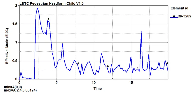
Comparision:-
In the case of rigidwall since the rigidwall is non deformable, it impacts harder so the strain reaches to 0.605 max. pressure at 6ms. During pedestrian head impact, the skin part of the head developes major amount of stress as it impacts the rigidwall at a short period of time. From the Pressure plot, it is found that the head impact occurs at time 2.2ms and the maximum Pressure produced during pedestrain head impact is 0.00195 at 2.4ms.
Resultant Acceleration Plot:-
Case-2
Case-3
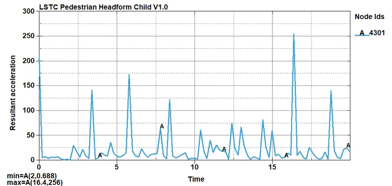
Comparision:-
The acceleration plot is drawn from the database node from the acceleration block in the pedestrian head model. It is found that the maximum resultant acceleration during the impact happens at 7ms which is 53.6mm/ms^2. In case with rigidwall, the maximum resultant acceleration is 256mm/ms^2 at 16.4ms.
HIC Plot:-
Case-2
Case-3
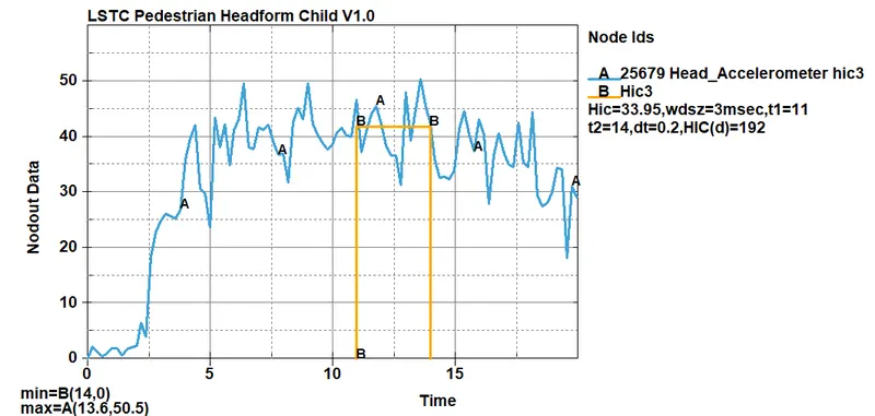
Comparision:-
From the HIC plot ,it can be seen that the value of HIC (Head Impact Coefiicient) in the case of rigidwall is 2034 which is a huge value of HIC factor since rigidwall is non deformable, it impacts harder so the HIC value is high in this case but in the case of hood, it is a plastic part which is obviously deformable so it impacts lesser comparatively that is why HIC value is less which is 33.95.
CONCLUSIONS:-
- For this project , using of include and define transforms cards was used to rotate the headform to the required orientation.
- Main files was used to call the headform file for this simulation.
- HIC values obtained can be used for the application of helmet design , active hood designs for the safety of the pedestrain.
- There is a drastic difference between the cases in terms of the HIC values , from the point of the manufacturing a hood - thickness and materials ability to deform plays a very important role in safety.