Week-7 Head Impact
Objective: To perform a Head Impact Simulation and calculate the Head Impact Coefficient (HIC) value in the LS-Prepost.
Unit System: kg-mm-ms
Introduction:
Pedestrian protection CAE is a part of vehicle safety engineering from a crash perspective. In pedestrian protection, one looks for imparting minimum injury to head, upper leg (thigh), and lower leg (including knee) in case of an accident with a human subject. These tests are usually done at a lower velocity from 20-40 kmph as accidents tend to result in more severe circumstances above these velocities and braking in case of an accident often results in collision at low velocities.
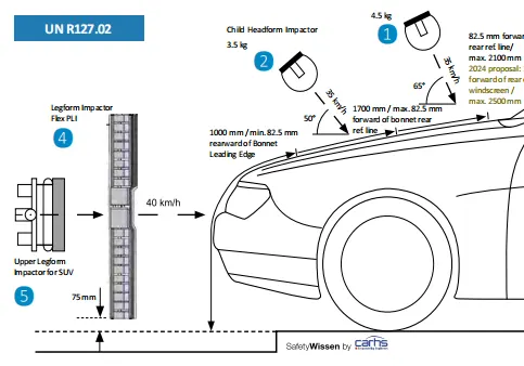
- Head Impact Coefficient (HIC)
Headfoam impactors are used to test the vehicle structure such as the hood. In a vehicle-pedstrian impact, the kinetics and severity of pedestrian injuries are affected by impact locations on the vehicle and body velocities after the impact. The objective of this project is to analyze the pedestrian kinematics in a Pedestrian-Vehicle accident scenarios and determine the Head Impact Coefficient (HIC) from the head resultant acceleration for head impacts on the vehicle hood. The Head Injury Criterion (HIC) model has been developed to measure quantitatively the head injury risk in crash situations.
The equation that is used for the measurement of the head injury of the whole model for the pedestrian head impact is head impact coefficient. HIC is calculated from the following equation:
`HIC=max_{t_1,t_2}{[ frac{1}{(t_2-t_1)} int_{t_1}^{t_2} a(t) dt ]^2.5 (t_2-t_1)}`
where
a= resulatant acceleration
`t_1 and t_2` are the two time instances which are which are recorded at the start and at the end when the HIC is maximum. The value of HIC is measured at the time interval between `t_2 -t_1`.
The value of the Head Impact Coefficient will be found out theoritically and from LS-Prepost in three differnet cases.
Case 1: A simple head model in the form of sphere impacting on a rigid wall.
Case 2: A standard pedestrian headfoam model impacting on a rigid wall.
Case 3: A standard pedestrian headfoam model impacting on a meshed hood.
We will demonstratre each cases one by one below with required inputs and outputs.
The simulation of a simple head impacting on the Rigid wall.
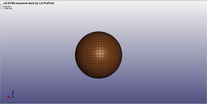
- Defining the parmaters of the spherical ball
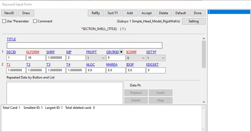
*SECTION_SHELL
This option is used to chose the shell element to be defined for the sphere. By using the ELFORM type 16 and thickness of the shell as 1mm and remaining paramters as default values the section was created.
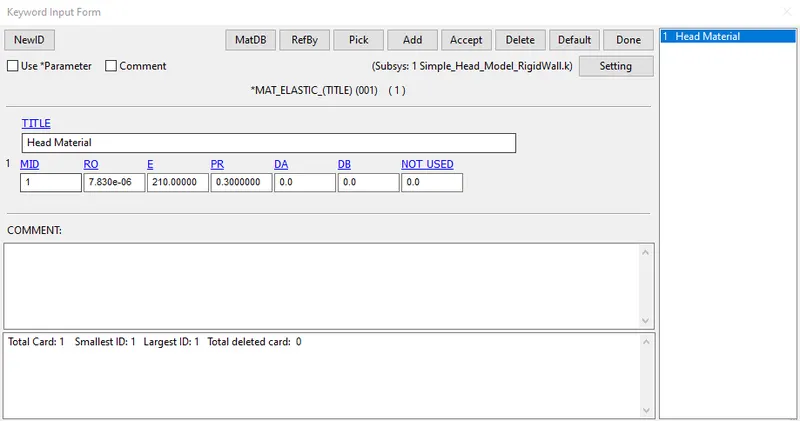
*MAT_ELASTIC_001
By creating a simple elastic material model for the simple head (meshed) that is provided, we define the parameters as follows taking steel material for reference.
Density, `rho = 7.83e-3{g}/{mm^3}`
Elastic Modulus, `E= 2.1e5` MPa
Poisson Ratio, `nu = 0.3`
Nect we create a rigid wall using the *RIGID_WALL keyword.
*RIGIDWALL_PLANAR
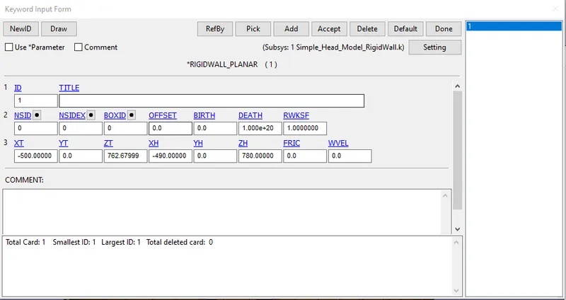
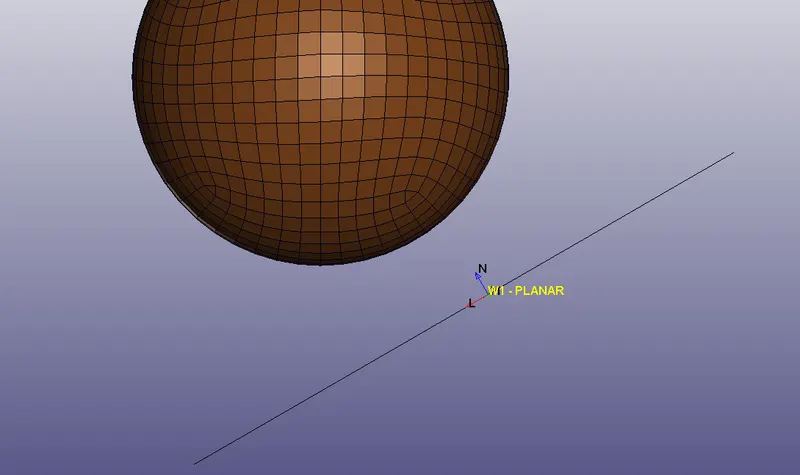
The rigid wall is inclined accordingly to replicate the behaviour of a car bonnet. Care should be taken that the normal to the plane should be always facing towards the ball by adjusting the values input to the head vector and tail vector respectively.
*DEFINE_COORDINATE_SYSTEM
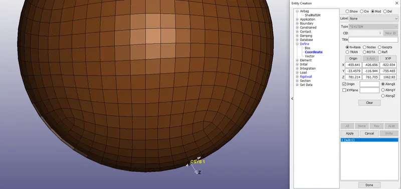
By clicking the create entity icon on the right toolbar, and choosing the option Define -> Coordinate, a local coordinate system is created using N+Xaxis as the option and 3 nodes are selected to define the local coordinate system. Further to initiliaze the velocity of the impact of the ball on the rigidwall, the above defined coordinate system is one way that can be used to define velocity in a particular axis.
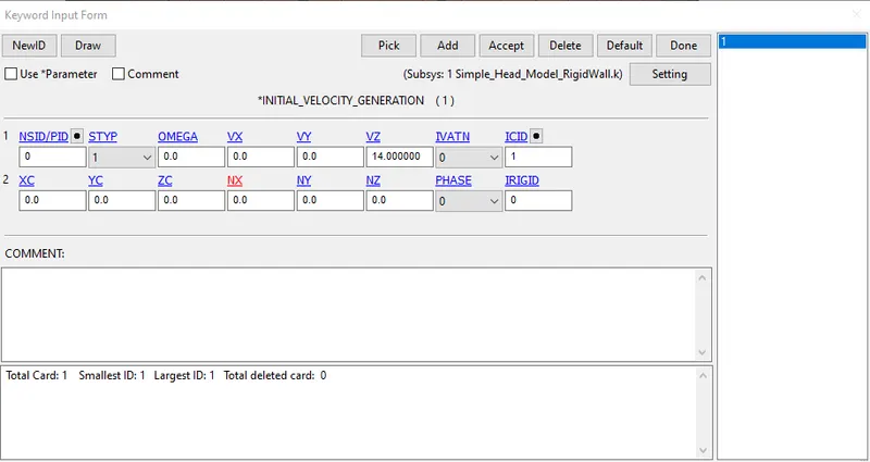
*INITIAL_VELOCITY_GENERATION
Since the tests are usually done at a lower velocity from 20-50 kmph as accidents tend to result in more severe circumstances above these velocities. The appropriate velocity chosen was 13.889ms for this analysis.
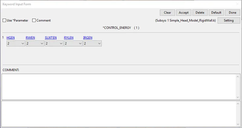
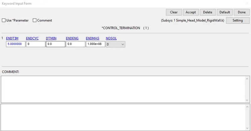
*CONTROL
The various control keywords used in this analysis are control energy and control termination. Using control energy all the energies are considered for simulation. Using control termination the end time is set to 5ms.
*DATABASE
- ASCII PLOT : GLSTAT, NODOUT, RWFORC
- BINARY_D3PLOT : The animation file is played for a time of 0.01ms.
Results
The following results are accumulated from the above case.
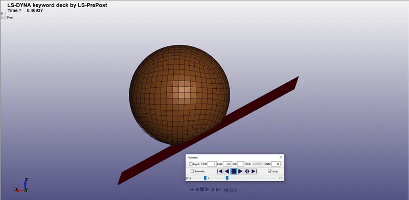
- Database Binary D3PLOT animated plot
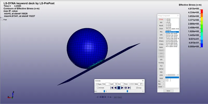
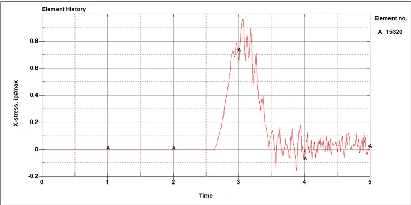
b. Effective Plastic Stress
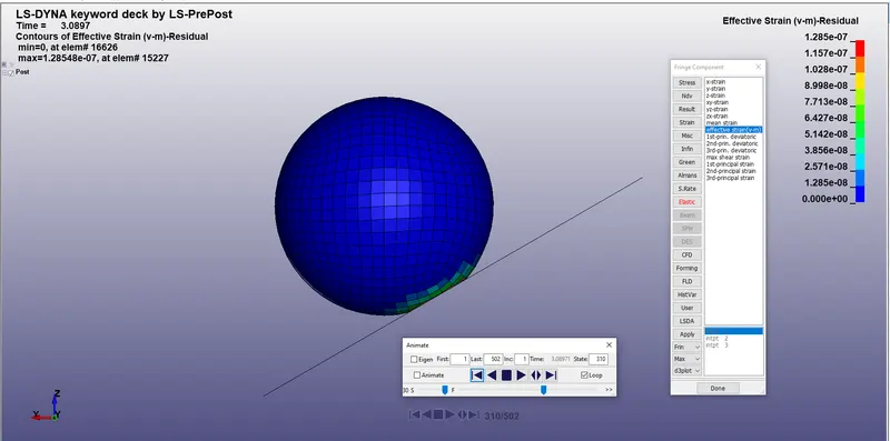
c. Effective plastic Strain
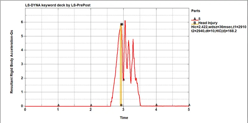
HIC calculated for simple head model impacted on a rigid wall
Other output options include
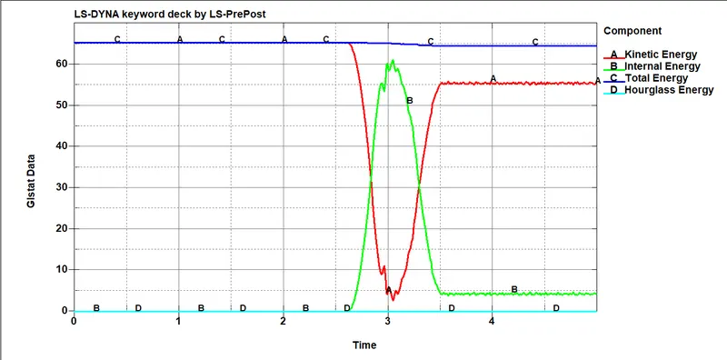
GLSTAT - Energy Graph
-------------------------------------------------------------------------------------------------------------------------------
Next we move to the second case which is
The simulation of a pedestrian headfoam impacting on the Rigid wall.
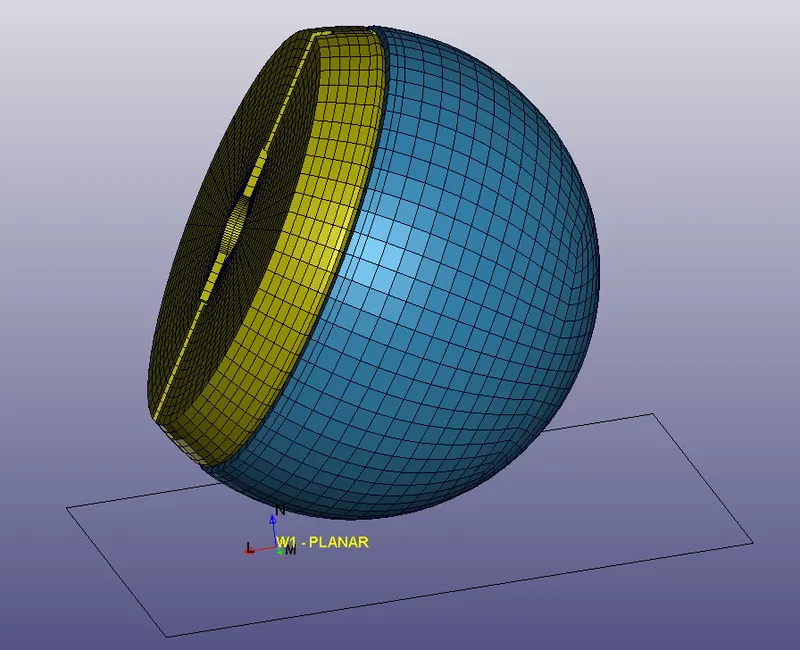
The test setup as per AIS 100 and the chosen angle of impact is 60 deg. The headfoam velocity was impact at `11.11{m}/{s}` (40 kmph). Impact point is on the rigidwall for second case and meshed hood for the third case.
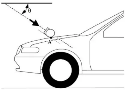
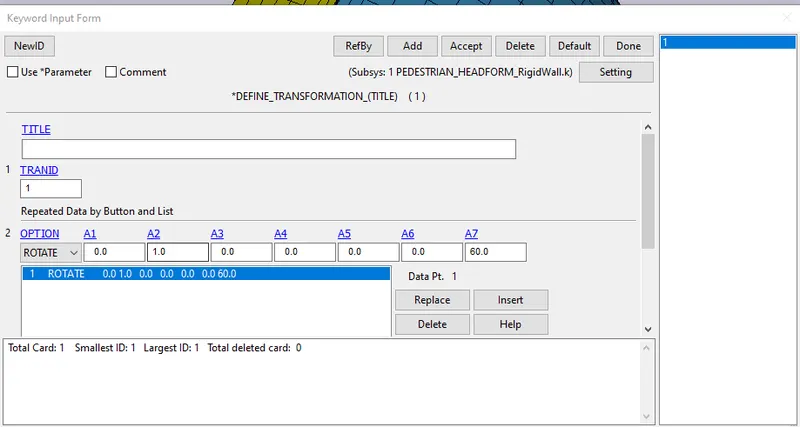
In the second and third case, the transformation of the original geometry is neccesary to replicate the real life scenario. To do this, we need to start with *DEFINE_TRANSFORMATION option present in the *DEFINE keyword. The define transformation option will be used to perform the rotate operation using OPTION parameter and setting the values from A1 to A7 by referring to the volume 1 manual under *DEFINE_TRANSFORMATION option.
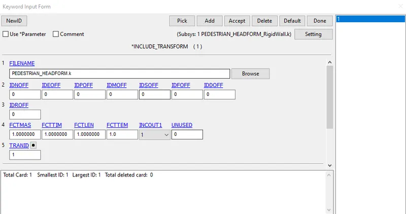
The operation initiated using ROTATE option in define transform is linked using TRANID present in the*INCLUDE_TRNASFORM located under the *INCLUDE keyword to a particular part or a subsystem (in this case Pedestrian Headform). In this option the subsystem is called using the FILENAME parameter where the required subsystem is present in the respective folder where the present input file is saved or the subsystem may be called from a different directory by defining the filepath. The original input file of the subsystem is not changed but it is called for transformation using this option. Further required input keywords are added in this new input file.
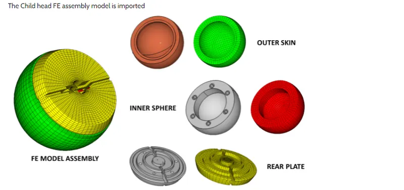
Accelerometer element was placed on the rear plate inside the inner sphere recess at the same location as its counterpart in the physical headform. *CONSTRAINED_EXTRA_NODE_SET was used to assign contacts between outer skin and inner skull of the headfoam. *CONSTRAINED_RIGID_BODIES was used between backplate and skull and between skull and accelerator block. *CONTACT_AUTOMATIC_SURFACE_TO_SURFACE was used to assign contacts between skull and the outer skin.
Similar to case 1, a rigidwall was created using the *RIGIDWALL_PLANAR option normal to z-axis. The elements used in the pedestian headform is already predefined in the subsystem. Similarly the materials and section used to analyze each part of the headform is also predefined using the material card and section card.
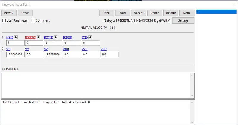
*INITIAL_VELOCITY
The inital velocity is set to 11.11mm/ms (40kmph) for this analysis. Now since the headform has to impact at a particular angle to the rigid wall, the required velocity is calculated and resolved along x and z-axis respectively.
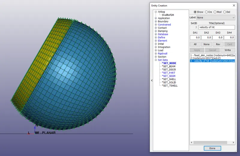
A set of nodes are created using *SET_NODE option present on clicking the create entity icon, wherby the set of nodes are selected to define the inital velocity of the headfoam whose setid is linked to intial velocity option using NSID parameter present in the card.
*CONTROL
- Control Termination: The termination time of the simulation is set to 4ms.
- Control Timestep: This card calculates the timestep automatically for all the elements and uses the minimum value for the analysis.
TSSFAC (Scale factor for computed time step) =0.9
DT2MS (Time step size for mass scaled solutions) =-0.0011
Negative DT2MS indicates mass is added for those elements whose time step size will be otherwise less than target time step size (TSSFAC *|DT2MS|)
*DATABASE
- BINARY_D3PLOT : The animation file is played for a time of 0.01ms.
- DATABASE_HISTORY_NODE_ID: A node on accelerator block of head were defined to measured the acceleration and the calculated HIC value.
- ASCII: GLSTAT, RWFORC, NODOUT
RESULTS
The following results are accumulated from the above case.
- Database Binary D3PLOT animated plot
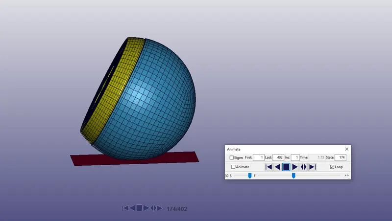
b. Effective Plastic Stress
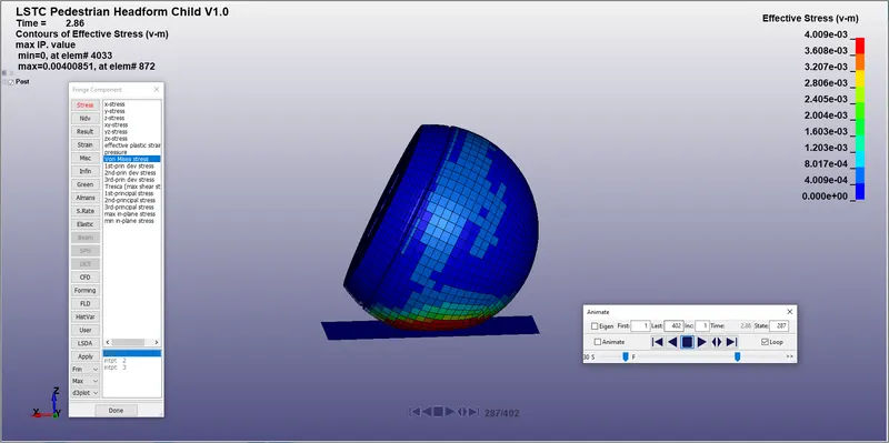
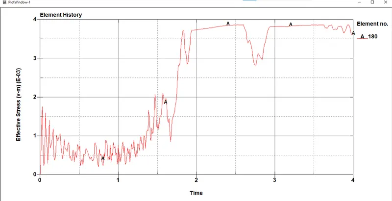
c. Effective Plastic Strain
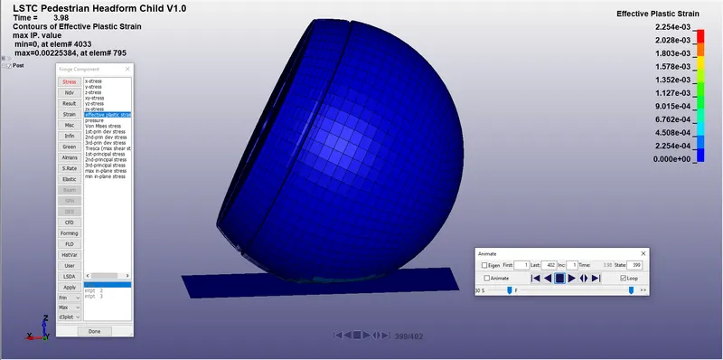
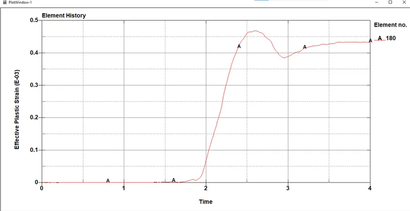
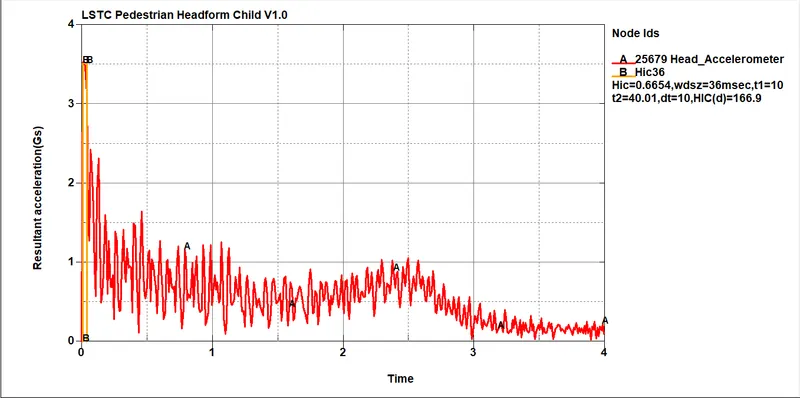
HIC calculated for pedestrian headfoam impacted on a rigid wall
Other output options include
GLSTAT - Energy Graph
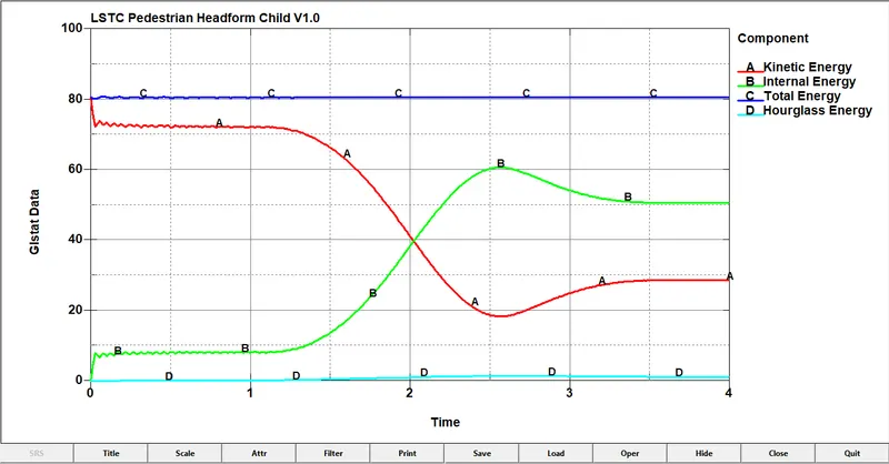
The energy plot represents the impact of headfoam on the rigid wall, where the kinetic energy of the headform decreases after impact and the internal energy of the headform increases after the impact. Since the outerskin is made of hyperelastic material there is gradual change in energy after the impact as compared to the enegy graph in the case of simple head model.
Lastly, we move to the third case which is
The simulation of a pedestrian headfoam impacting on the meshed hood.
In this case, the rigid wall will be replaced with the meshed hood input file provided at the start of the project. This will depict a real life scenario of a pedestrian head impact collision with a vehicle.
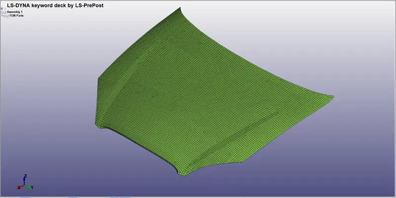
To start simulating this case, we open a new LS-Prepost file and use the *INCLUDE keyword present in the keyword manager to call the two subsystems : Pedestrain Headfoam and Meshed hood. Some procedures similar to case 2 is performed beforehand to incline the headfoam hitting on the hood at angle using define transformation and include transformation and later the file is saved and called using *include keyword.
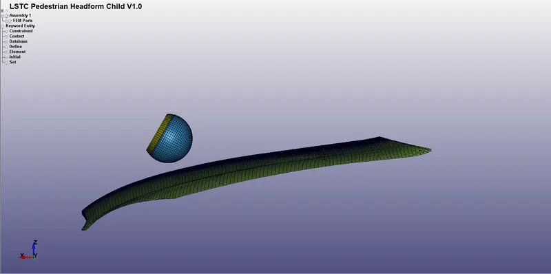
The meshed hood input file is opened and the parameters of the hood are set accordingly as follows-
*SECTION
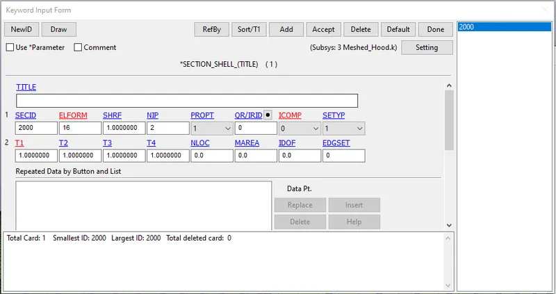
The section is chosen as ELFORM type 16 with thickness as 1mm and NIP as 2. Rest of the values are kept default.
*MAT
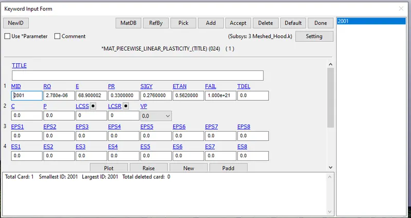
For the hood, one can use Aluminium as suggested in the requirement of the project. It is defined using MAT_024 - Linear Piecewise Plasticity option using *MAT keyword in Keyword manager. The plasticity part of the project is addressed using tangent modulus variable.
*CONTACT
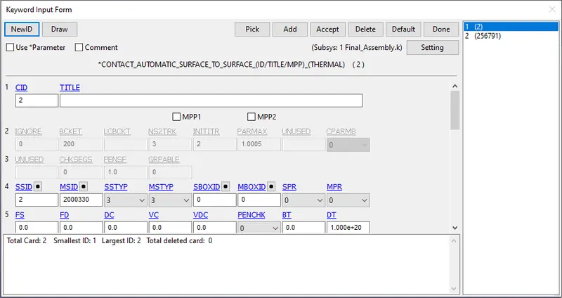
- CONTACT_AUTOMATIC_SURFACE_TO_SURFACE
A contact between skin surface and hood surface has been defined using the above option by choosing the slave as the skin and master as hood.
*CONTROL
- Control Termination: The termination time of the simulation is set to 10 ms.
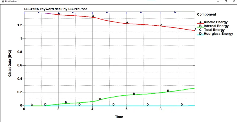
- Control Energy: All the energies are to be considered while plotting the data present in the glstat file
- Control Timestep: This card calculates the timestep automatically for all the elements and uses the minimum value for the analysis.
TSSFAC (Scale factor for computed time step) =0.9
DT2MS (Time step size for mass scaled solutions) =-0.0011
Negative DT2MS indicates mass is added for those elements whose time step size will be otherwise less than target time step size (TSSFAC *|DT2MS|)
*DATABASE
- BINARY_D3PLOT : The animation file is played for a time of 0.01ms.
- DATABASE_HISTORY_NODE_ID: A node on accelerator block of head were defined to measured the acceleration and the calculated HIC value.
- ASCII: GLSTAT, RWFORC, NODOUT
RESULTS
The following results are accumulated from the above case.
- Database Binary D3PLOT animated plot
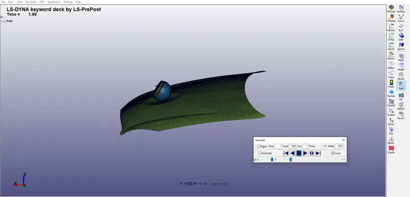
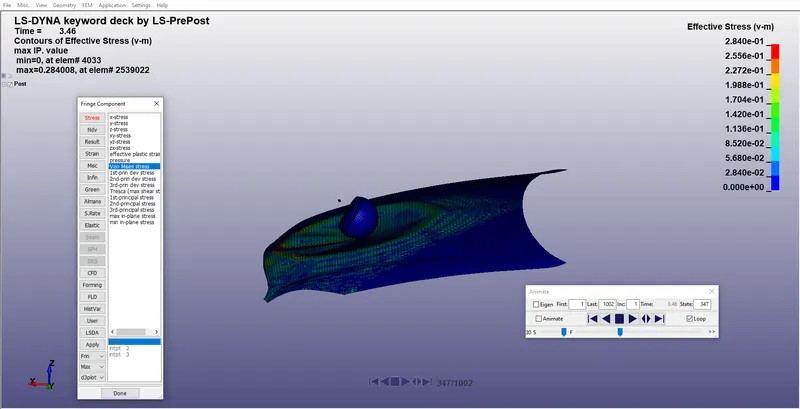
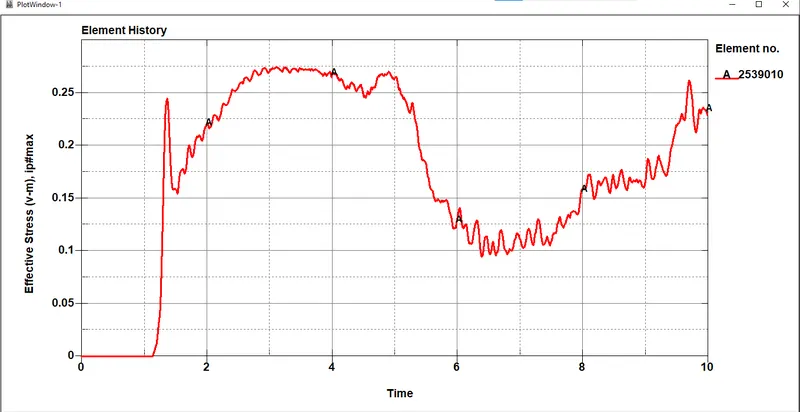
b. Effective Plastic Stress
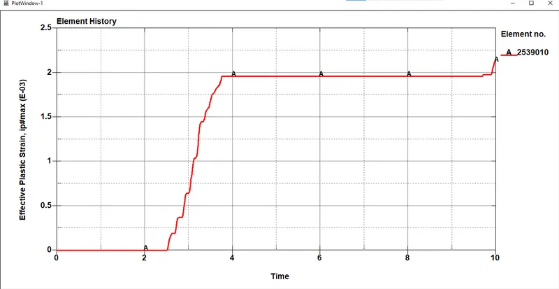
c. Effective Plastic Strain
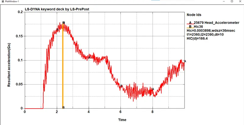
HIC calculated for pedestrian headfoam impacted on a meshed hood
Other output options include
GLSTAT - Energy Graph
Conclusion:
The three cases are solved as per requirement in the above project. The case 3, where the pedestrian headfoam hits the meshed hood is a real life scenario which can be explained in a much better way and analysis can be performed with more insights can be drawn but due to limited computational resources we are finding only the Head Impact Coefficient (HIC) in all the above cases.