Week-7 Head Impact
Goals:
To simulate the head impact under following cases.
1. Simple head impacting rigid wall
2. Headform impact with rigid wall
3. Headform impact with hood
---------------------------------------------------------------------------
Deliverables:
1. Stress-strain plot
2. Head acceleration plot
3. HIC value
4. Stress-Strain comparison for rigidwall and hood
---------------------------------------------------------------------------
Given problem boundary conditions:
1. *INCLUDE_TRANSFORM and *DEFINE_TRANSFORMATION should be used
2. Head impact angle should be between 35 - 75 degrees
4. Elastic head material
---------------------------------------------------------------------------
Brief Description of the problem and backgroud of pedestrian safety
~~~~~~~~~~~~~~~~~~~~~~~~~~~~~~~~~~~~~~~~~~
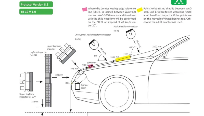
ECE R78 and EURO NCAP Regulation: Pedestrian safety and injury mitigation is crucial. ECE R78 and EURO NCAP define the requirements for an pedestrian protection. Follwoing figure shows the test protocol for the pedestrian safety test. The child impact-dummy is impacted on the bonnet at an angle of 50 degree with 40 km/h impact velocity. The injury levels especially, head injury criterion (HIC) is evaluated which gives quantified injury levels.
Head Injury Criterion (HIC) :
Head injury criterion is an average acceleration between a given time t1 and t2. There are 3 HIC values, HIC 36, HIC 15 and HIC 3. A HIC36 value of 1000 would produce the same injuries as of HIC15 equal to 700. Hence in automotive safety assessment protocols, HIC36=1000 and HIC15=700 are used as lower limits for injuries. Following formula gives the HIC.
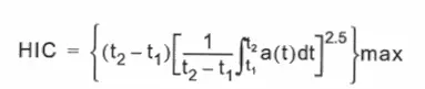
t1 -t2 can be 36 ms or 15 mins or 3 ms.
_________________________________________________________________________________________
Solution Procedure:
Case 1: Simple headform (Ball) impacting rigid wall
_________________________________________________________________________________________
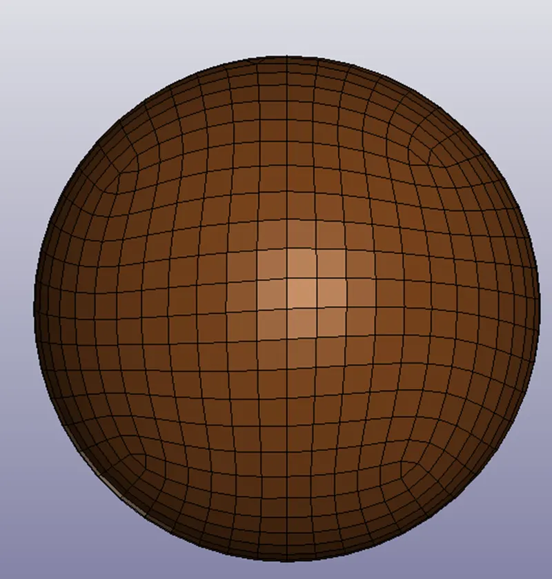
1. Given Headform is loaded
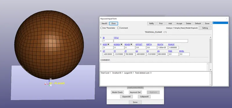
2. Rigidwall is created
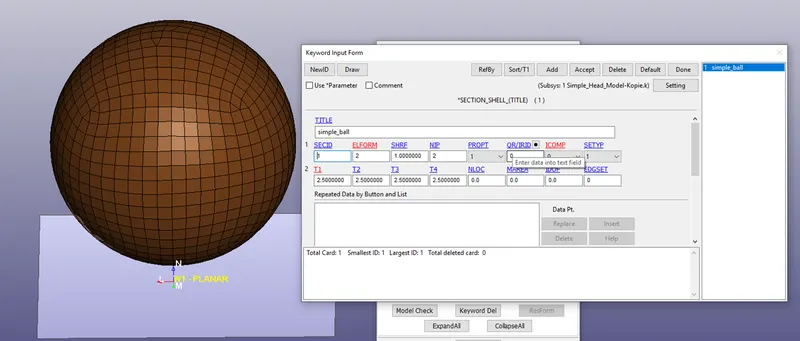
3. Section with ELEFORM 2 (2.5 mm thick) is created
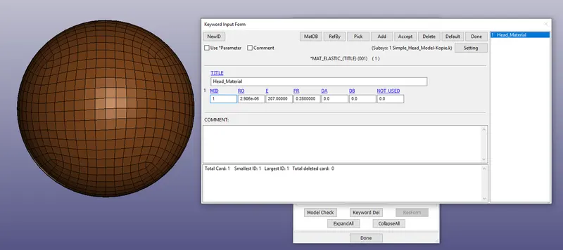
4. Head material is created
5. Head nodeset is created and initial velocity (-11.11 in -Z) is asssigned
6. 3 ms ENDTIM is assigned in *CONTROL_TERMINATION
7. DATABASE_BINARY_D3PLOT is requseted at 0.1 ms
8. GLSTAT, MATSUM, NODOUT, SLEOUT are requested in DATABASE_ASCII_OPTION
Results:
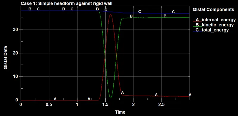
SImulation is verified by compaing the energies. Total emergy is approximately constant. Kinetic energy decreases and internal energy increases.
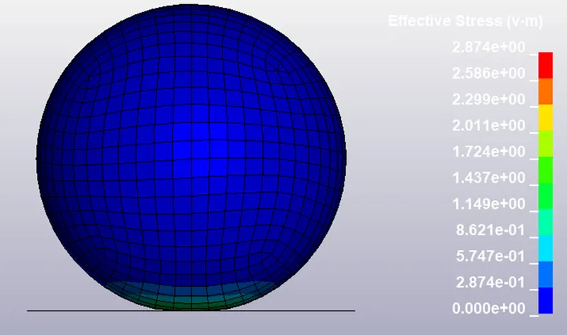
Maximum Effective Stress
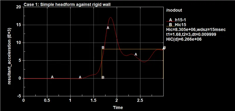
Head acceleration is plotted
NOTE: It is unrealistic to plot and calculate the HIC because,
1. Node acceleration is not rigifbody acceleration
2. Acceleration is not measured at CG of the head
3. We need minimum 15 ms impact window, which is not available.
But since it was the boundary conditions of the problem to calculate the HIC, it is calculated here. Otherwise, claculatin HIC is not meaningful here.
______________________________________________________________________________________
Case 2: Child headform impacting rigidwall
______________________________________________________________________________________
Step 1: Define transformation and include transformation
*DEFINE_TRANSFORMATION is defined to rotate the given child headform and then *INCLUDE_TRANSFORMATION is used to import the headform and assign the transformation.
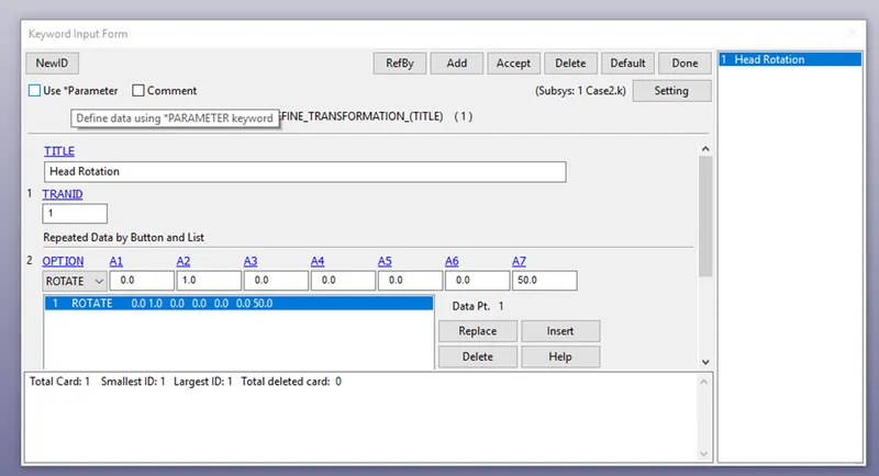
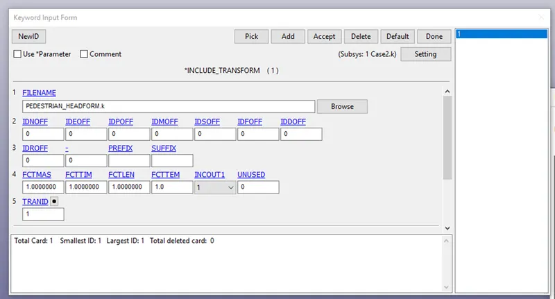
Step 2: Keyword is saved in a new file and opened again. Follwoing figure shows the rotated headform. In addition, similar to first case, a planar rigidwall is created using *RIGIDWALL_PLANAR keyword.
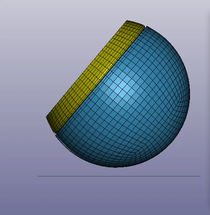
Step 3: Boundary condition (Initial Velocity): The nodes of the headform are selected and a nodeset is created and initial velocity is assigned. (Note: 11.11 m/s is resolved into X and Y components and then assigned)
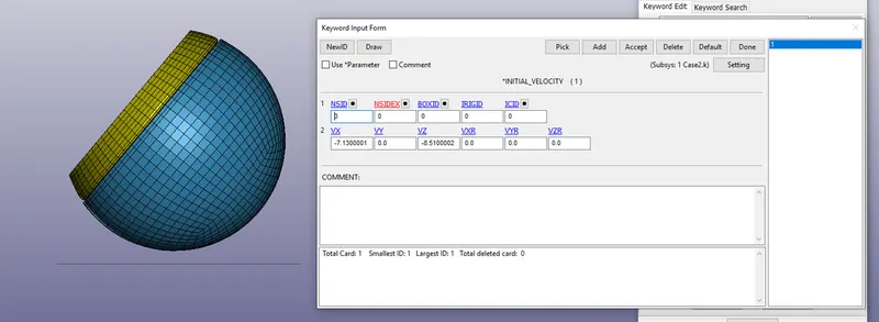
Remaining Cards:
*CONTROL*TIMESTEP:
TSSFAC (Time step scaling factor) is set to 0.9 followed by mass scaling (DT2MS) equal to -0.0011.
*CONTROL_TERMINATION is used to define 5ms termination time.
in *DATABASE_OPTION, ASCII filed are requested for following parameters at every 0.1 ms,
1. GLSTAT
2. MATSUM
3. NODOUT
4. RWFORC
*DATABASE_EXTENT_BINARY card is used with STRFLG=1 to compute elastic strain.
Then the keyword file is checked for errorrs and then solved in HPC cluster (SMP Double)
Results: Firstly all the energies are cimpared to verify the simulation correctness. We can observe that, TE is constant and KE drops during impact and IE increases. Hence, now flaws are observed till this phase.
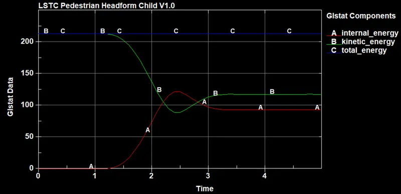
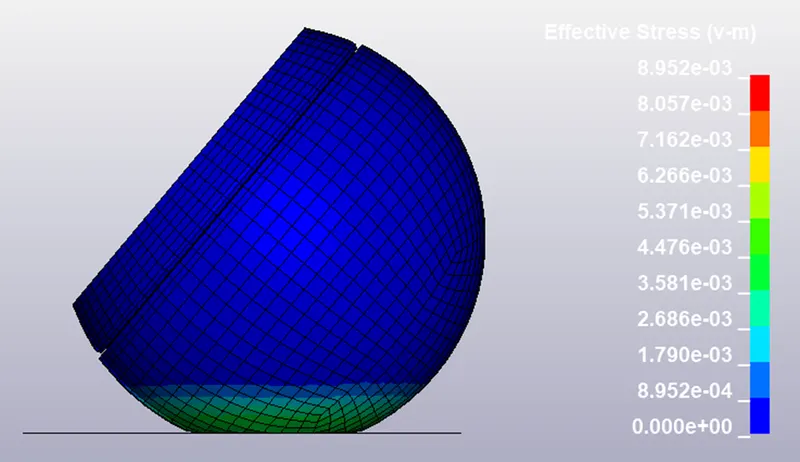
Following figure shows effecttive stress.
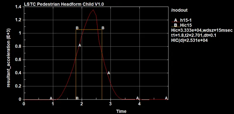
Following figure shows the acceleration plot with HIC calculation. However, again HIC15 calculation in this case is also inappropriate sicne acceleration peak lasts less than 5 ms. Due to problem requirement, HIC is calculated which is 2.531e+4.
______________________________________________________________________________________
Case 3: Child headform impact against hood
______________________________________________________________________________________
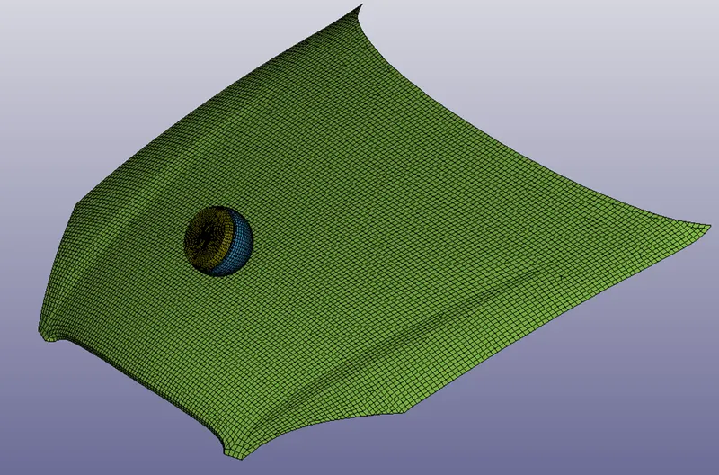
Step 1: Transforming the headform and loading the hood.
Similar to previous case, *DEFINE_TRANSFORMATION and *INCLUDE_TRANSFORMATION cards are used to rotate teh head. Then the headform is imported into the hood file as shown in the following figure.
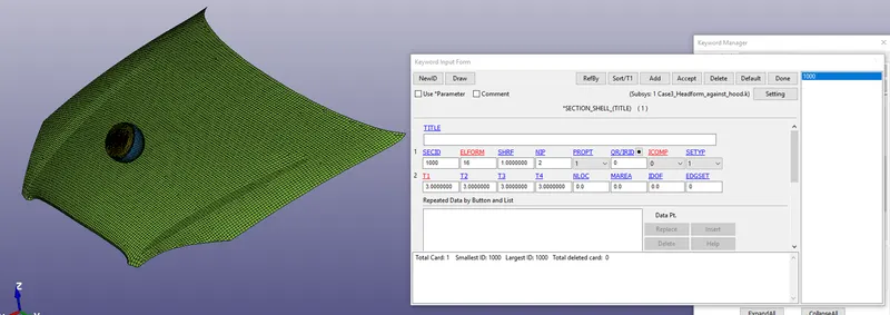
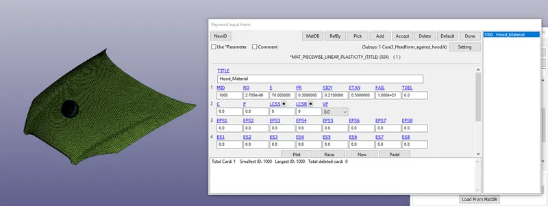
Step 2:Material and Section.
Section and material are assigned to the hood part as shown in following figures.
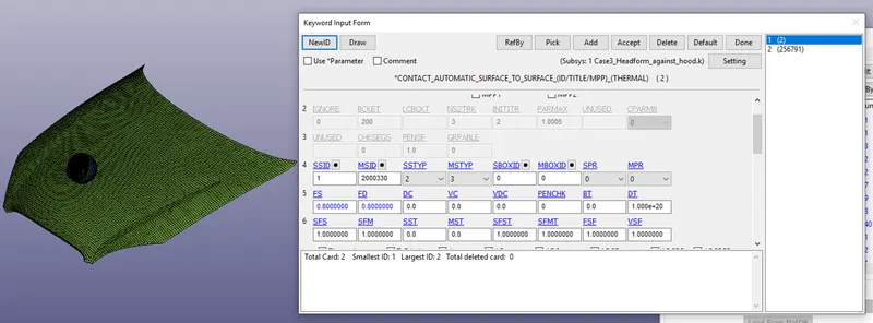
Step3: Contact
Automatic surface to surface contact is assigned between headform and the hood.
Step 4: Boundary conditions:
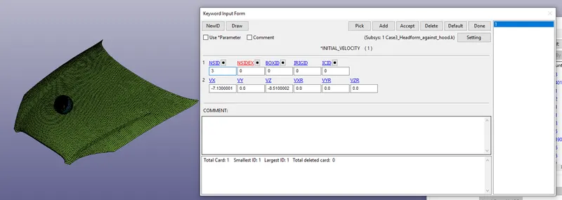
Initial velocity is assigned to the head by resolving X and Y components.
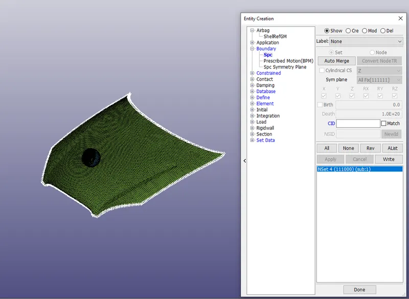
Hood is constrained in X, Y and Z directions (linear and rotation) along the edges.
 Following control and database cards are used.
*CONTROL_TERMINATION, ENDTIM =50ms
*CONTROL_TIMESTEP
TSSFAC=0.9
DT2MS=-0.0011
DATABASE_OPTION
GLSTAT, MATSUM, NODOUT
*DATABASE_EXTENT_BINARY, STRFLG=1 --> Strain output
*DATABSE_HISTORY_NODE_ID=25679 (Head accelerometer)
Finally, keyword is checked for the errors and solved using HPC solver
Results:
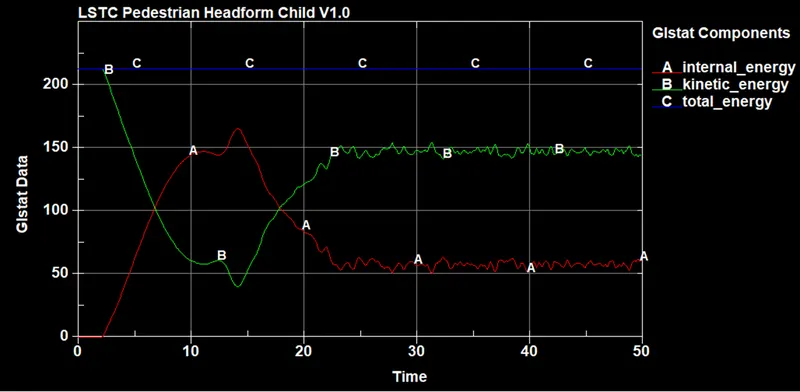
Energies are verified and it was observed that,
TE is constant,
KE reduces
IE increases
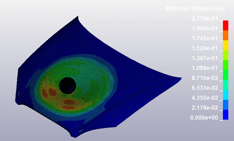
Effective Stress
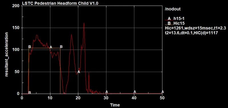
We can observe that the peak acceleration during the impact is close to 140g and impact lasted for more than 15 ms. Further, we have an accelerometer at the CG of the head which gives the rigidbody motion of the head. Hence in this case it is appropriate to calculate the HIC. The HIC value is 1117 which shows severe injuries.
Conclusion:
1. Three impacts cases,
a) Simple head (ball) impacting the wall
b) Child headform impact rigidwall
c) Child headform impacting hood
were simulated in this exercise. Following conclusions were drawn,
1. Impact time for impact against rigidwall is less than 5 ms. Hence, HIC calculation is inappropiate.
2. Nodal acceleration in simple cases does not represent rigidbody motion
3. The HIC15 for impact against hood was 1117, which is higher than the Eueo NCAP limit.
Learnings of the exercise:
Impact analysis in automotive pedestrian safety problems
understanding and calculation of HIC using LS-PrePost