Week - 5 - Modelling Spotwelds
Aim: Simulation of spot welded plates crashing a rigidwall.
Given conditions:
1. Beam and solid elements to be used for spotwelds.
2. Steel material is to be used for spotwelds.
3. *MAT_SPOTWELD card has to be used.
4. Spotwelds have to be symmetric
Considerations:
1. Initial velocity 50 km/h
2. 5 spotwelds are considered.
3. g/mm/ms unit system is followed throughout the simulations
Important note: Only beam element spotweld simulation is shown here. In the second simulation, beam elements are replaced by solid elements at the same spots and simulated.
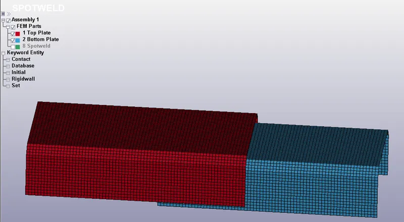
Step 1: The given .key file is loaded and, parts and title are renamed
Step 2: Material assignment
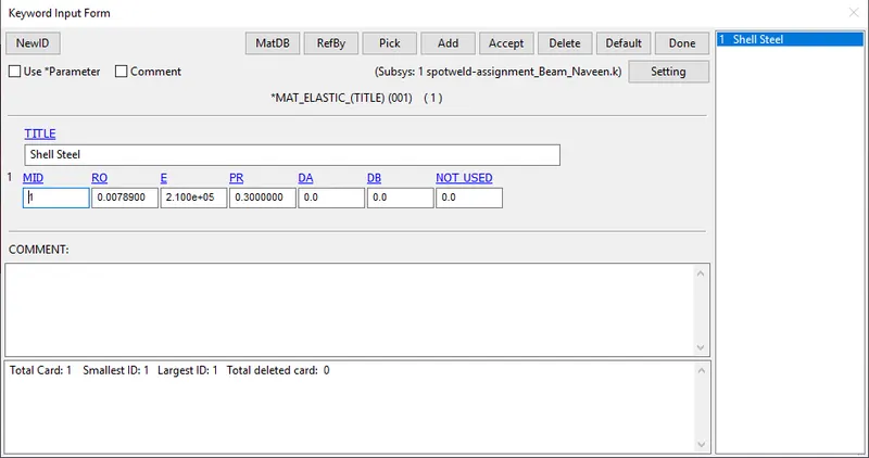
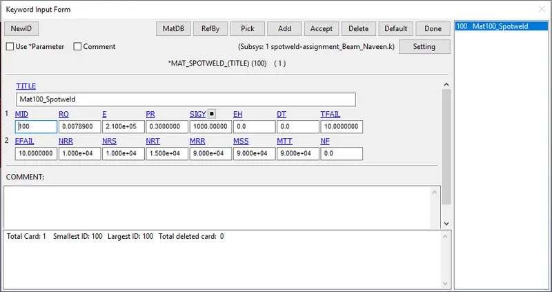
For the plates *MAT_ELASTIC material is assigned and spotwelds *MAT_SPOTWELD is assigned
Step 3: Section assignment
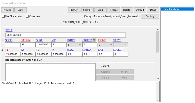
Shell elements with ELEFORM 16 and 2 mm thickness are assigned to plates
For the spotweld beam elements ELEFORM 9 elements with 3 mm thickness are assigned. (*MAT_SPOTWELD requires ELEFORM 9). Solid elements with ELEFORM 1 are created for solid element spotweld.
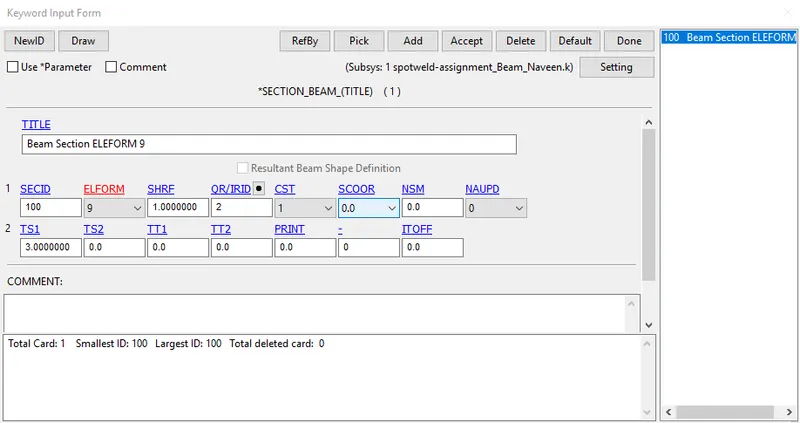
Step 4: Spotweld creation
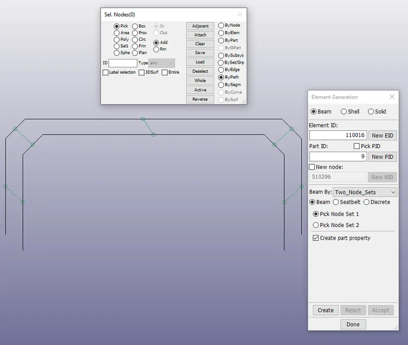
Beam elements are created symmetrically using element generation command. Two_Node_Sets are used one each on top plate and bottom plate.
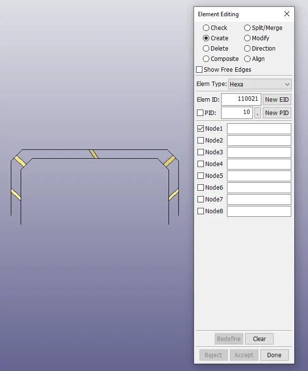
In case of solid element spotweld solid elements are generated through EleTol command. Eight nodes are picked. Four one top plate and four on bottom plate.
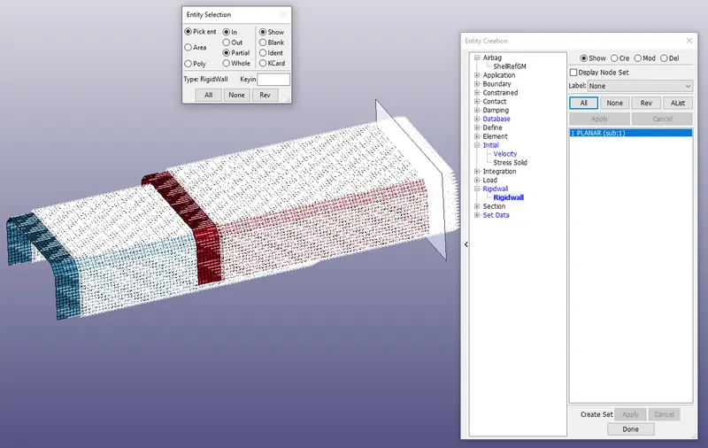
Step 5: Rigidwall creation and initial velocity
A rigidwall at 10 mm distance from leading edge of top plate is created. An initial velocity equivalent to 50km/h is assigned to all the parts.
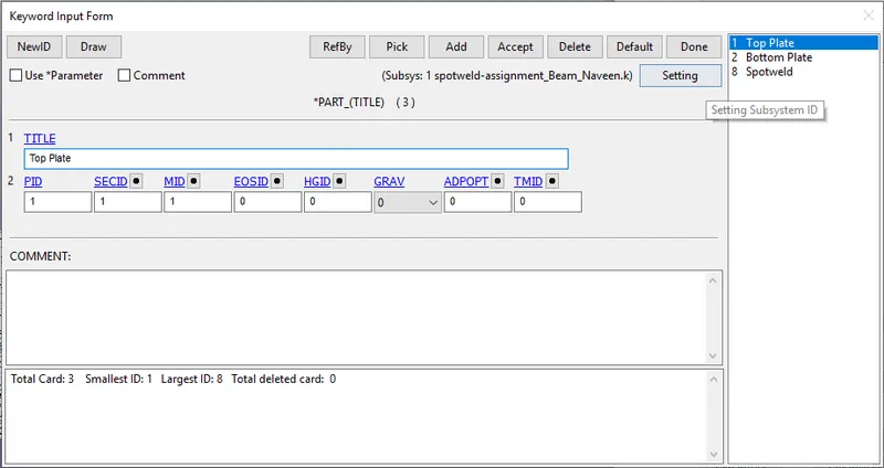
Step 6: Plates and welds are assigned materials and sections in part card.
Step 7: All parts are assigned with *AUTOMATIC_SINGLE_SURFACE contact to avoid penetration during failure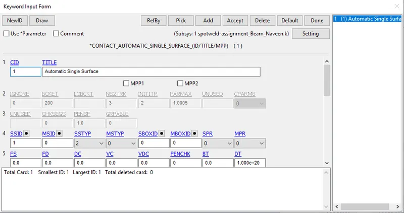
Step 8: Control card
Hourglass energy is selected and simulation for 20 ms is defined in the control card.
Step 9: Database
Binary d3plot at 0.5 ms time-step is requested.
Databsed history node is requested for nodes 501044, 501321, 502710, 504510 and 504273 bides, which are spotweld nodes in nodes in beam spotweld.
Under the ASCII_OPTION default dt is set to 0.5 ms and ELEOUT, GLSTAT, MATSUM, NODOUT, RCFORC, SWFORC are requested.
Step 9: Finally model is checked for the errors and keyword file is written and solved in the solver.
Results:
Both the simulations have normal termination.
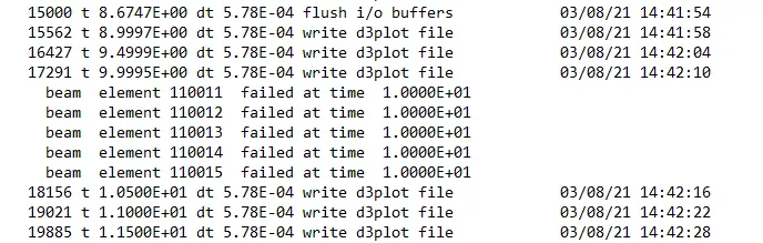
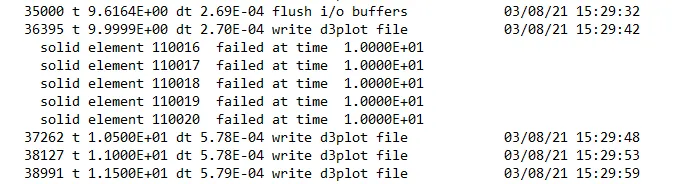
Step 10: It is to be noted that simulation is run for 20 ms and welds are expected to fail at half of the termination time. The log file shows failure of beam elements exactly at half-time i.e. 10ms. In solid elements also elements fail at 10 ms.
Step 11: Energy
Left image --> Beam
Right image --> Solid
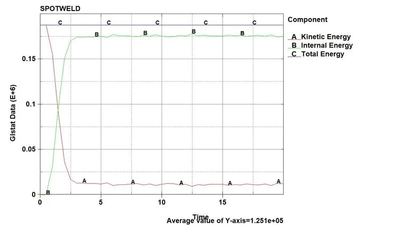
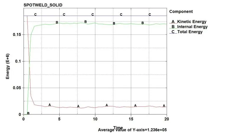
As soon as the structure hits the wall, the kinetic starts to drop and internal energy of the parts increase. The total energy of the parts till end of the simulation is constant, which proves the validity of the simulation. The sliding energy is almost zero, since parts do not slide, instead there is a head-on impact (Forgot to show in the graph).
Von-Mises Stress
Left Image --> Beam
Right Image --> Solid
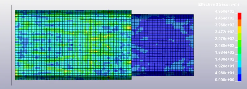
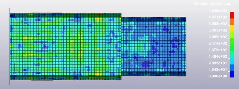
The images show stress at 1.49 ms after the impact. It can be clearly seeen that, there is high stress concentration at the welded areas.
Axial Force
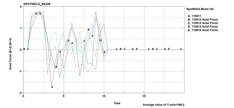
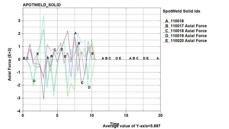
Due to the solid elements which are subjected compression and tension, the axial force in solid elements is less than beam elements which are 1D elements.
Shear Force
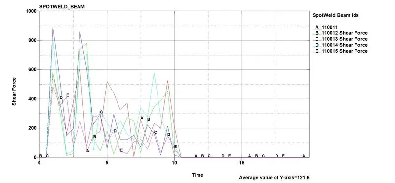
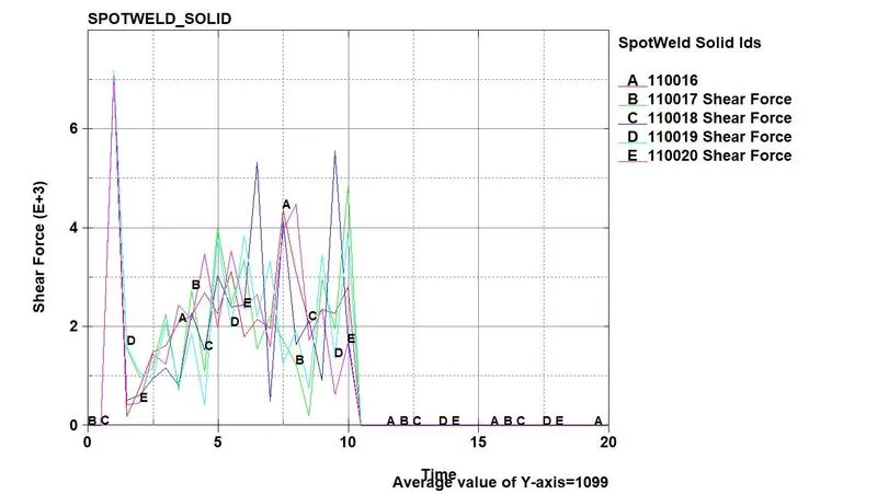
A solid element is hex element with 8 nodes. They experience greater shear force than the beam elements. From the graph it can be seen that shear force in solid spotwelds is approximately 10*shear force on the beams. Hence solid weld is advantageous when shearing of the plates is crucial.
Resultant Acceleration
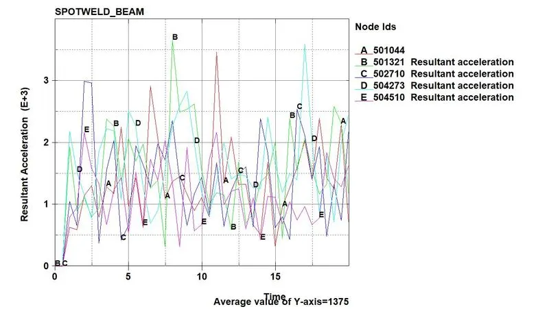
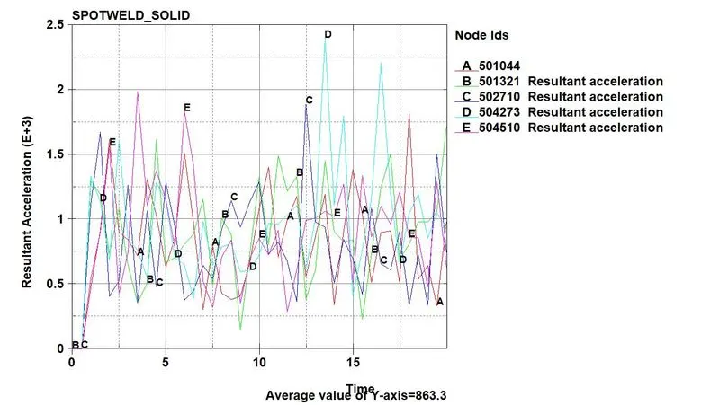
Acceleration in solid spotweld part is less than the beam spotwelds.
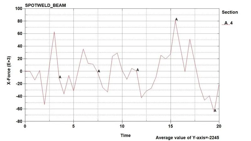
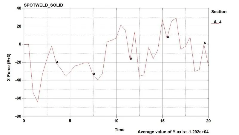
Force in beam welded parts is higher than solid elements parts. The analysis depends on at which time force analysis is required.
Conclusion: Spotwelds using beam elements and solid elemets are simulated. The welds with solid elements offer better shear strength compared to beam elements. Since solid elements are hex elements, the shearing can be represented correctly. Selection of the weld should depend on the forces acting on the parts.